EP0673048A1 - Arc quenching device with arc quenching blades - Google Patents
Arc quenching device with arc quenching blades Download PDFInfo
- Publication number
- EP0673048A1 EP0673048A1 EP95100888A EP95100888A EP0673048A1 EP 0673048 A1 EP0673048 A1 EP 0673048A1 EP 95100888 A EP95100888 A EP 95100888A EP 95100888 A EP95100888 A EP 95100888A EP 0673048 A1 EP0673048 A1 EP 0673048A1
- Authority
- EP
- European Patent Office
- Prior art keywords
- arc
- quenching
- plates
- extinguishing
- plate
- Prior art date
- Legal status (The legal status is an assumption and is not a legal conclusion. Google has not performed a legal analysis and makes no representation as to the accuracy of the status listed.)
- Granted
Links
Images
Classifications
-
- H—ELECTRICITY
- H01—ELECTRIC ELEMENTS
- H01H—ELECTRIC SWITCHES; RELAYS; SELECTORS; EMERGENCY PROTECTIVE DEVICES
- H01H9/00—Details of switching devices, not covered by groups H01H1/00 - H01H7/00
- H01H9/30—Means for extinguishing or preventing arc between current-carrying parts
- H01H9/34—Stationary parts for restricting or subdividing the arc, e.g. barrier plate
- H01H9/36—Metal parts
Definitions
- the invention relates to an arc extinguishing device according to the preamble of claim 1.
- a known arc quenching device of this type is located together with an associated switch in a closed space filled with an electronegative quenching gas.
- the quenching plates assembled into a package are arranged one behind the other in the direction of movement of an arc-pulling switching piece of the switch in the event of a shutdown and offset in the longitudinal direction so that the distance between the arc-pulling end of the switching piece and the facing edges of the quenching plates in the course of Switch-off movement increases.
- a disadvantage of this arrangement is that due to the staggered arrangement of the quenching plates, the quenching plate stack is basically arranged in a diamond-shaped manner and is thus extended in the diagonal direction.
- the invention has for its object to take measures in an arc extinguishing device according to the preamble of claim 1, by means of which a substantial improvement of the arc extinguishing effect is achieved with simple means in a compact construction.
- an arc extinguishing device with perforated quenching plates, which are preferably made of expanded metal
- the quenching plates can be used in a cuboid arrangement and thus in the usual compact embodiment. In switching tests in the medium-voltage range at 24 kV, the cut-off power was increased from approximately 200 amperes to approximately 700 amperes in the case of a cuboidal fire-extinguishing plate arrangement.
- a medium-voltage switch-disconnector 1 In a room (not shown) filled with an electronegative extinguishing gas, in particular sulfur hexafluoride (SF6), there is a medium-voltage switch-disconnector 1, the movable contact piece 1.1 of which is pivotally supported at one end about an axis 2 and whose switching piece end 1.2 is connected when an load current is switched off closed switching path with a fixed contact 1.3 is in an electrically conductive slide system.
- the contact piece 1 To open the switching path 1.2, 1.3, the contact piece 1 is pivoted away from the fixed contact 1.3 by means of a drive rod 3 which is articulated thereon, the free contact piece end 1.2 leaves the fixed contact piece 1.3 on an arc horn 1.4 provided thereon.
- SF6 sulfur hexafluoride
- the contact piece 1.1 In the direction of movement of the contact piece 1.1, adjacent to the arcing horn 1.4, there is a quenching plate packet 4 with individual quenching plates 5, which are arranged parallel to one another at a distance as a cuboid block.
- the quenching plates 5 lie one behind the other in the direction of movement of the switching element 1.1.
- the arc-pulling free contact piece end 1.2 only approaches the extinguishing plate edges located there after a predetermined swivel angle to a minimum distance a and moves away from the adjacent extinguishing plate edges during further swiveling.
- the longitudinal axis 1.5 of the movable contact piece 1.1 runs at the point of greatest proximity to the quenching plates 5 in a plane to which the quenching plates 5 lie in parallel planes.
- At least one of the quenching plates 5, but preferably all of them, are provided with a plurality of openings 6, which in particular are regularly distributed over the surface, as shown in FIG. 2.
- These quenching plates 5 are preferably made of expanded metal with diamond-shaped openings 6, the webs 7 surrounding the openings 6 being inclined with respect to the plane of the quenching plate.
- the center distance between adjacent quenching plates 5 is approximately 1/10 of the greatest edge length of the quenching plate 5 and is preferably approximately 7 mm.
- the extinguishing plates 5 can optionally have at their edge facing the contact 1.1 a cutout open towards the contact end 1.2, the width of which can be greater than the width of the free contact end 1.2.
- the contact piece 1.1 is preferably designed as a switch blade which is rotatably mounted at one end and which contacts the fixed contact piece 1.3 on opposite sides in order to achieve an optimal current transfer with a low contact resistance.
- the arc horn 1.4 runs in particular parallel to the adjacent first quenching plate of the quenching plate stack and is connected to it in a metallic and electrically conductive manner.
Abstract
Description
Die Erfindung betrifft eine Lichtbogenlöscheinrichtung gemäß dem Oberbegriff des 1. Anspruchs.The invention relates to an arc extinguishing device according to the preamble of
Eine bekannte Lichtbogenlöscheinrichtung dieser Art befindet sich zusammen mit einem zugeordneten Schalter in einem abgeschlossenen, mit einem elektronegativen Löschgas gefüllten Raum. Die zu einem Paket zusammengesetzten Löschbleche sind in Bewegungsrichtung eines im Abschaltfalle einen Lichtbogen ziehenden Schaltstücks des Schalters mit gegenseitigem Abstand hintereinander angeordnet und in Längsrichtung so zueinander versetzt, daß der Abstand zwischen dem den Lichtbogen ziehenden Ende des Schaltstücks und den zugewandten Kanten der Löschbleche im Laufe der Ausschaltbewegung zunimmt. Ein Nachteil ist bei dieser Anordnung, daß durch die versetzte Anordnung der Löschbleche das Löschblechpaket im Grunde rautenförmig angeordnet ist und dadurch eine vergrößerte Erstreckung in Diagonalrichtung erfährt.A known arc quenching device of this type is located together with an associated switch in a closed space filled with an electronegative quenching gas. The quenching plates assembled into a package are arranged one behind the other in the direction of movement of an arc-pulling switching piece of the switch in the event of a shutdown and offset in the longitudinal direction so that the distance between the arc-pulling end of the switching piece and the facing edges of the quenching plates in the course of Switch-off movement increases. A disadvantage of this arrangement is that due to the staggered arrangement of the quenching plates, the quenching plate stack is basically arranged in a diamond-shaped manner and is thus extended in the diagonal direction.
Der Erfindung liegt die Aufgabe zugrunde, bei einer Lichtbogenlöscheinrichtung gemäß dem Oberbegriff des 1. Anspruchs Maßnahmen zu treffen, durch welche bei gedrängter Bauweise mit einfachen Mitteln eine wesentliche Verbesserung der Lichbogenlöschwirkung erzielt wird.The invention has for its object to take measures in an arc extinguishing device according to the preamble of
Die Lösung dieser Aufgabe erfolgt gemäß der Erfindung durch die kennzeichnenden Merkmale des 1. Anspruchs.This object is achieved according to the invention by the characterizing features of
Bei einer Ausgestaltung einer Lichtbogenlöscheinrichtung gemäß der Erfindung mit gelochten Löschblechen, die vorzugsweise aus Streckmetall hergestellt sind, ergibt sich eine Verbesserung der Lichtbogenlöschwirkung gegenüber ungelochten Löschblechen in einem solchen Maße, daß mit dem zugeordneten Schalter der drei- bis vierfache Abschaltstrom beherrscht werden kann. Dabei können die Löschbleche in quaderförmiger Anordnung und damit in üblicher gedrängter Ausführungsform zur Anwendung gelangen. Bei Schaltversuchen im Mittelspannungsbereich bei 24 kV wurde die Abschaltleistung bei quaderförmiger Löschblechanordnung von etwa 200 Ampere auf etwa 700 Ampere gesteigert. Dabei waren dem schwenkbar angelenkten beweglichen Schaltstück des Schalters jeweils 13 Löschbleche der Größe 72 mm x 55 mm bei je 7 mm Mittenabstand zugeordnet. Die durchbrochenen Lichtbogenlöschbleche bestanden aus handelsüblichem, an der Oberfläche feuerverzinktem Streckmetall, das mit rautenähnlichen Durchbrüchen von etwa 5 mm x 2 mm versehen war. Es wird dabei davon ausgegangen, daß die erhöhte Löschwirkung darauf beruht, daß die Teillichtbögen, die an den Durchbruchstegen zwischen den einzelnen Löschblechen brennen, durch das bei brennendem Lichtbogen auftretende Druckgeschehen im Löschblechpaket intensiv mit unbelastetem Löschgas, insbesondere FS6 umspült und dadurch stark gekühlt und somit gelöscht werden. Der Zustrom von durch Lichtbogeneinwirkung unbelasteten Löschgasanteilen in die einzelnen Löschkammerabschnitte wird dabei durch die in den Löschblechflächen vorgesehenen Druchbrüche wesentlich erleichtert, wobei gleichzeitig eine intensive Vermischung durch Verwirbeln von belastetem und unbelstetem Löschgas zu vermuten ist. Andererseits bieten die Durchbrüche auch den Vorteil, daß das durch den Lichtbogen thermisch belastete und stark expandierende Löschgas aus den Teilkammern abströmen und durch unbelastetes Löschgas ersetzt werden kann. Das Lichtbogenplasma wird demnach durch die Turbulenzen mit frischem Löschgas vermengt und abgekühlt, was zu einer raschen Erhöhung der Spannungsfestigkeit der Schaltstrecke führt. Dadurch werden die Lichtbogenzeiten und damit die Gesamtbelastung der Schaltanordnung wesentlich vermindert. Es ergibt sich zudem eine sehr geringe Streuung der Lichtbogenzeiten und dadurch ein sehr stabiles Schaltverhalten.In an embodiment of an arc extinguishing device according to the invention with perforated quenching plates, which are preferably made of expanded metal, there is an improvement in the arc quenching effect compared to unperforated quenching plates to such an extent that the three to four times the shutdown current can be controlled with the associated switch. The quenching plates can be used in a cuboid arrangement and thus in the usual compact embodiment. In switching tests in the medium-voltage range at 24 kV, the cut-off power was increased from approximately 200 amperes to approximately 700 amperes in the case of a cuboidal fire-extinguishing plate arrangement. 13 swiveling plates of size 72 mm x 55 mm, each with 7 mm center distance, were assigned to the pivotably articulated moving contact piece of the switch. The perforated arc-quenching plates consisted of commercially available expanded metal, which was hot-dip galvanized on the surface and provided with diamond-like openings of approximately 5 mm x 2 mm. It is assumed that the increased extinguishing effect is due to the fact that the partial arcs, which burn at the breakthrough webs between the individual extinguishing plates, are flushed intensively with unloaded extinguishing gas, in particular FS6, due to the pressure occurring in the arc plate package when the arc is burning, and are therefore strongly cooled and thus strongly cooled to be deleted. The inflow of quenching gas portions unencumbered by the action of an arc into the individual quenching chamber sections is considerably facilitated by the breakthroughs provided in the quenching plate surfaces, and at the same time intensive mixing by swirling loaded and unstressed quenching gas can be assumed. On the other hand, the breakthroughs also have the advantage that the arc is thermally stressed and strongly expanding extinguishing gas flow out of the subchambers and can be replaced by unloaded extinguishing gas. The turbulence mixes the arc plasma with fresh quenching gas and cools it, which leads to a rapid increase in the dielectric strength of the switching path. As a result, the arc times and thus the total load on the switching arrangement are significantly reduced. There is also very little spreading of the arc times and therefore very stable switching behavior.
Weitere vorteilhafte Ausgestaltungen des Erfinungsgegenstands sind in den zusätzlichen Ansprüchen angegeben.Further advantageous refinements of the subject matter of the invention are specified in the additional claims.
Die Erfindung ist nachfolgend anhand der Prinzipdarstellungen eines Ausführungsbeispiels näher erläutert.The invention is explained in more detail below on the basis of the basic representations of an exemplary embodiment.
Es zeigen:
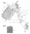
- Fig. 1: eine Lichtbogenlöscheinrichtung mit zugeordnetem Schalter in einer Seitenschnittdarstellung und
- Fig. 2: eine Ansicht eines mit Durchbrechungen versehenen Löschblechs.
- Fig. 1: an arc extinguishing device with an associated switch in a side sectional view and
- 2: a view of an extinguishing plate provided with openings.
In einem nicht dargestellten, mit einem elektronegativen Löschgas, insbesondere Schwefelhexafluorid (SF6), gefüllten Raum befindet sich ein Mittelspannungs-Lasttrennschalter 1, dessen bewegliches Schaltstück 1.1 einendig schwenkbar um eine Achse 2 gelagert ist und dessen bei Abschaltung eines Laststroms einen Lichtbogen ziehendes Schaltstückende 1.2 bei geschlossener Schaltstrecke mit einem feststehenden Schaltstück 1.3 in elektrisch leitender Gleitanlage steht. Zum Öffnen der Schaltstrecke 1.2, 1.3 wird das Schaltstück 1 mittels einer daran schwenkbar angelenkten Antriebsstange 3 vom feststehenden Kontakt 1.3 weggeschwenkt, wobei das freie Schaltstückende 1.2 das feste Schaltstück 1.3 an einem daran vorgesehenen Lichtbogenhorn 1.4 verläßt. In der Bewegungsrichtung des Schaltstücks 1.1 findet sich benachbart zum Lichtbogenhorn 1.4 ein Löschblechpaket 4 mit einzelnen Löschblechen 5, die parallel zueinander mit Abstand als quaderförmiger Block angeordnet sind. Die Löschbleche 5 liegen dabei in der Bewegungsrichtung des Schaltstücks 1.1 hintereinander. Das lichtbogenziehende freie Schaltstückende 1.2 nähert sich erst nach einem vorbestimmten Schwenkwinkel bis auf einen Minimumabstand a an die dort befindlichen Löschblechkanten und entfernt sich beim weiteren Schwenken von den jeweils benachbarten Löschblechkanten. Die Längsachse 1.5 des beweglichen Schaltstücks 1.1 verläuft im Punkt der größten Annäherung an die Löschbleche 5 in einer Ebene, zu der die Löschbleche 5 in parallelen Ebenen liegen.In a room (not shown) filled with an electronegative extinguishing gas, in particular sulfur hexafluoride (SF6), there is a medium-voltage switch-
Um ein zuverlässiges Löschen eines Lichtbogens zwischen dem festen Kontaktstück 1.3 und dem sich davon entfernenden Schaltstück 1.1 insbesondere bei hohen Stromstärken zu erreichen, ist wenigstens eines der Löschbleche 5, vorzugsweise jedoch alle mit mehreren Durchbrüchen 6 versehen, die sich insbesondere regelmäßig über die Oberfläche verteilen, wie es Fig. 2 darstellt. Dabei bestehen diese Löschbleche 5 vorzugsweise aus Streckmetall mit rautenförmigen Durchbrüchen 6, wobei die die Durchbrüche 6 umgebenden Stege 7 gegenüber der Löschblechebene geneigt sind. Durch die Durchbrüche wird ein intensiver Gasaustauschs zwischen den einzelnen Löschblechkammern ermöglicht, so daß die in diesen Kammern 8 brennenden Teillichtbögen aufgrund der vom Lichtbogen erzeugten Druckänderung und er daraus resultierenden Gasströmung durch die einzelnen Löschbleche hindurchströmen, dabei stark gekühlt werden und erlöschen. Die verbesserte Durchströmung des Löschblechpakets bewirkt dabei eine wesentlich gesteigerte Vermischung von belastetem mit unbelastetem Löschgas, wobei die an den geneigten Stegen 7 entstehenden Turbulenzen den Mischvorgang noch steigern. Dadurch erfährt das durch den Lichtbogen erhitzte Gas eine starke Kühlung durch noch nicht unmittelbar am Löschvorgang beteiligte Löschgasteile, wodurch das Lichtbogenplasma schnell abgekühlt wird und ein steiler Anstieg der Spannungsfestigkeit der gesamten Schaltstrecke eintritt.In order to reliably extinguish an arc between the fixed contact piece 1.3 and the contact piece 1.1 moving away therefrom, in particular at high current intensities, at least one of the
Der Mittenabstand zwischen benachbarten Löschblechen 5 beträgt etwa 1/10 der größten Kantenlänge des Löschblechs 5 und beträgt vorzugsweise etwa 7 mm. Dabei können die Löschbleche 5 gegebenenfalls an ihrer dem Schaltstück 1.1 zugewanden Kante einen zum Schaltstückende 1.2 hin offenen Ausschnitt aufweisen, dessen Breite größer als die Breite des freien Schaltstückendes 1.2 sein kann. Außerdem ist das Schaltstück 1.1 vorzugsweise als einendig drehbar gelagertes Schaltmesser ausgebildet, welches das feststehende Schaltstück 1.3 an gegenüberliegenden Seiten kontaktiert, um einen optimalen Stromübergang bei geringem Übergangswiderstand zu erreichen. Das Lichtbogenhorn 1.4 verläuft insbesondere parallel zum benachbarten ersten Löschblech des Löschblechpakets und ist mit diesem metallisch und elektrisch leitend verbunden.The center distance between
Claims (11)
Applications Claiming Priority (2)
| Application Number | Priority Date | Filing Date | Title |
|---|---|---|---|
| DE4409495 | 1994-03-19 | ||
| DE4409495A DE4409495A1 (en) | 1994-03-19 | 1994-03-19 | Arc quenching device with quenching plates |
Publications (2)
| Publication Number | Publication Date |
|---|---|
| EP0673048A1 true EP0673048A1 (en) | 1995-09-20 |
| EP0673048B1 EP0673048B1 (en) | 1998-04-01 |
Family
ID=6513296
Family Applications (1)
| Application Number | Title | Priority Date | Filing Date |
|---|---|---|---|
| EP95100888A Expired - Lifetime EP0673048B1 (en) | 1994-03-19 | 1995-01-24 | Arc quenching device with arc quenching blades |
Country Status (2)
| Country | Link |
|---|---|
| EP (1) | EP0673048B1 (en) |
| DE (2) | DE4409495A1 (en) |
Citations (5)
| Publication number | Priority date | Publication date | Assignee | Title |
|---|---|---|---|---|
| GB300575A (en) * | 1927-11-15 | 1929-10-03 | Siemens Ag | Improvements in or relating to electrical switches |
| FR1075587A (en) * | 1953-02-27 | 1954-10-18 | Allis Chalmers Mfg Co | Improvements relating to an electric circuit switch or circuit breaker |
| CH399564A (en) * | 1961-02-20 | 1965-09-30 | Licentia Gmbh | Arc extinguishing chamber for electrical switchgear |
| EP0028012A1 (en) * | 1979-10-27 | 1981-05-06 | Fuji Electric Co. Ltd. | Low-tension circuit breaker |
| EP0157242A2 (en) * | 1984-04-04 | 1985-10-09 | Felten & Guilleaume Energietechnik AG | Arc extinguishing means for electrical-load switches |
Family Cites Families (6)
| Publication number | Priority date | Publication date | Assignee | Title |
|---|---|---|---|---|
| DE1040103B (en) * | 1957-03-20 | 1958-10-02 | Wissenschaftlich Tech Buero Fu | Erase insert for electrical switchgear |
| DE1126010B (en) * | 1960-09-16 | 1962-03-22 | Licentia Gmbh | Loeschblechordnung for low voltage switchgear |
| DE3820489A1 (en) * | 1988-06-16 | 1989-12-21 | Felten & Guilleaume Energie | Encapsulated switch disconnector arrangement |
| DE3912726A1 (en) * | 1989-02-08 | 1990-08-09 | Siemens Ag | ARC CHAMBER WITH EXTINGUISHING SHEETS |
| DE4141685C2 (en) * | 1991-12-18 | 1996-07-04 | Sachsenwerk Ag | Switchgear for medium or high voltage |
| DE4219673A1 (en) * | 1992-06-16 | 1993-12-23 | Emitec Emissionstechnologie | Automative catalytic converter corrugated and flat sheet metal substrate - where sheet metal substrates consist of elongated metal strips first drawn out then smoothed |
-
1994
- 1994-03-19 DE DE4409495A patent/DE4409495A1/en not_active Ceased
-
1995
- 1995-01-24 EP EP95100888A patent/EP0673048B1/en not_active Expired - Lifetime
- 1995-01-24 DE DE59501744T patent/DE59501744D1/en not_active Expired - Lifetime
Patent Citations (5)
| Publication number | Priority date | Publication date | Assignee | Title |
|---|---|---|---|---|
| GB300575A (en) * | 1927-11-15 | 1929-10-03 | Siemens Ag | Improvements in or relating to electrical switches |
| FR1075587A (en) * | 1953-02-27 | 1954-10-18 | Allis Chalmers Mfg Co | Improvements relating to an electric circuit switch or circuit breaker |
| CH399564A (en) * | 1961-02-20 | 1965-09-30 | Licentia Gmbh | Arc extinguishing chamber for electrical switchgear |
| EP0028012A1 (en) * | 1979-10-27 | 1981-05-06 | Fuji Electric Co. Ltd. | Low-tension circuit breaker |
| EP0157242A2 (en) * | 1984-04-04 | 1985-10-09 | Felten & Guilleaume Energietechnik AG | Arc extinguishing means for electrical-load switches |
Also Published As
| Publication number | Publication date |
|---|---|
| DE59501744D1 (en) | 1998-05-07 |
| DE4409495A1 (en) | 1995-09-21 |
| EP0673048B1 (en) | 1998-04-01 |
Similar Documents
| Publication | Publication Date | Title |
|---|---|---|
| DE60030840T2 (en) | CIRCUIT BREAKER | |
| DE735829C (en) | Circuit breaker | |
| DE4410108C2 (en) | Arc quenching chamber with three barriers for the passage of arc gases | |
| DE60029919T2 (en) | POL FOR AN ELECTRIC POWER SWITCH INCLUDING AN ARC FLASH CHAMBER WITH DIELECTRIC SHIELDS | |
| DE741695C (en) | Circuit breaker | |
| DE915358C (en) | Circuit breaker | |
| DE2441561A1 (en) | SWITCHING PART OF A COMPRESSED GAS SWITCH WITH BLOWING OUT THE ARC WITH COMPRESSED GAS | |
| EP1032942B1 (en) | Switching device with an electric arc extinguishing device | |
| DE10291133B4 (en) | Housing for a switching device | |
| DE672867C (en) | Switch with arc extinguishing by flowing compressed gas | |
| WO1993013538A1 (en) | Automatic cutout with an arc extinguishing chamber | |
| EP0959483B1 (en) | Load break switch with arc extinguishing chamber | |
| EP0673048B1 (en) | Arc quenching device with arc quenching blades | |
| EP0051756B1 (en) | Arc extinguishing device, in particular for an automatic cut out | |
| DE4243314A1 (en) | Current limiting switch with additional attenuating switch action | |
| DE4041887A1 (en) | ARC CHAMBER FOR AN ELECTRICAL SWITCHGEAR | |
| DE3018254C2 (en) | ||
| DE1182323B (en) | Electric switch with a chimney used to extinguish the arc | |
| EP0626708B1 (en) | Load break switch | |
| EP0603503B1 (en) | Method for switching a fused load-break switch and fused load-break switch | |
| DE2923235A1 (en) | Low tension circuit breaker - with cylindrical plastic rod in arc chamber for gas release by arc action | |
| DE1790089C3 (en) | ||
| DE1081540B (en) | Circuit breaker | |
| EP0335823A1 (en) | Combination of switching apparatuses comprising a low-tension power circuit breaker and a current-limiting switching device | |
| DE584993C (en) | Device for arc extinguishing in liquid switches |
Legal Events
| Date | Code | Title | Description |
|---|---|---|---|
| PUAI | Public reference made under article 153(3) epc to a published international application that has entered the european phase |
Free format text: ORIGINAL CODE: 0009012 |
|
| AK | Designated contracting states |
Kind code of ref document: A1 Designated state(s): DE FR GB IT NL SE |
|
| 17P | Request for examination filed |
Effective date: 19960214 |
|
| 17Q | First examination report despatched |
Effective date: 19970127 |
|
| GRAG | Despatch of communication of intention to grant |
Free format text: ORIGINAL CODE: EPIDOS AGRA |
|
| GRAG | Despatch of communication of intention to grant |
Free format text: ORIGINAL CODE: EPIDOS AGRA |
|
| GRAH | Despatch of communication of intention to grant a patent |
Free format text: ORIGINAL CODE: EPIDOS IGRA |
|
| GRAH | Despatch of communication of intention to grant a patent |
Free format text: ORIGINAL CODE: EPIDOS IGRA |
|
| GRAA | (expected) grant |
Free format text: ORIGINAL CODE: 0009210 |
|
| AK | Designated contracting states |
Kind code of ref document: B1 Designated state(s): DE FR GB IT NL SE |
|
| GBT | Gb: translation of ep patent filed (gb section 77(6)(a)/1977) |
Effective date: 19980402 |
|
| REF | Corresponds to: |
Ref document number: 59501744 Country of ref document: DE Date of ref document: 19980507 |
|
| ET | Fr: translation filed | ||
| ITF | It: translation for a ep patent filed |
Owner name: JACOBACCI & PERANI S.P.A. |
|
| PG25 | Lapsed in a contracting state [announced via postgrant information from national office to epo] |
Ref country code: SE Free format text: LAPSE BECAUSE OF FAILURE TO SUBMIT A TRANSLATION OF THE DESCRIPTION OR TO PAY THE FEE WITHIN THE PRESCRIBED TIME-LIMIT Effective date: 19980701 |
|
| PLBE | No opposition filed within time limit |
Free format text: ORIGINAL CODE: 0009261 |
|
| STAA | Information on the status of an ep patent application or granted ep patent |
Free format text: STATUS: NO OPPOSITION FILED WITHIN TIME LIMIT |
|
| 26N | No opposition filed | ||
| REG | Reference to a national code |
Ref country code: GB Ref legal event code: IF02 |
|
| NLT1 | Nl: modifications of names registered in virtue of documents presented to the patent office pursuant to art. 16 a, paragraph 1 |
Owner name: ALSTOM SACHSENWERK GMBH |
|
| NLT1 | Nl: modifications of names registered in virtue of documents presented to the patent office pursuant to art. 16 a, paragraph 1 |
Owner name: AREVA SACHSENWERK GMBH |
|
| REG | Reference to a national code |
Ref country code: FR Ref legal event code: CD |
|
| REG | Reference to a national code |
Ref country code: FR Ref legal event code: CD |
|
| PGFP | Annual fee paid to national office [announced via postgrant information from national office to epo] |
Ref country code: IT Payment date: 20100125 Year of fee payment: 16 |
|
| PGFP | Annual fee paid to national office [announced via postgrant information from national office to epo] |
Ref country code: GB Payment date: 20100128 Year of fee payment: 16 |
|
| PGFP | Annual fee paid to national office [announced via postgrant information from national office to epo] |
Ref country code: NL Payment date: 20100121 Year of fee payment: 16 |
|
| PGFP | Annual fee paid to national office [announced via postgrant information from national office to epo] |
Ref country code: FR Payment date: 20110201 Year of fee payment: 17 Ref country code: DE Payment date: 20110322 Year of fee payment: 17 |
|
| REG | Reference to a national code |
Ref country code: NL Ref legal event code: V1 Effective date: 20110801 |
|
| GBPC | Gb: european patent ceased through non-payment of renewal fee |
Effective date: 20110124 |
|
| PG25 | Lapsed in a contracting state [announced via postgrant information from national office to epo] |
Ref country code: GB Free format text: LAPSE BECAUSE OF NON-PAYMENT OF DUE FEES Effective date: 20110124 |
|
| PG25 | Lapsed in a contracting state [announced via postgrant information from national office to epo] |
Ref country code: NL Free format text: LAPSE BECAUSE OF NON-PAYMENT OF DUE FEES Effective date: 20110801 Ref country code: IT Free format text: LAPSE BECAUSE OF NON-PAYMENT OF DUE FEES Effective date: 20110124 |
|
| REG | Reference to a national code |
Ref country code: FR Ref legal event code: ST Effective date: 20120928 |
|
| PG25 | Lapsed in a contracting state [announced via postgrant information from national office to epo] |
Ref country code: DE Free format text: LAPSE BECAUSE OF NON-PAYMENT OF DUE FEES Effective date: 20120801 |
|
| REG | Reference to a national code |
Ref country code: DE Ref legal event code: R119 Ref document number: 59501744 Country of ref document: DE Effective date: 20120801 |
|
| PG25 | Lapsed in a contracting state [announced via postgrant information from national office to epo] |
Ref country code: FR Free format text: LAPSE BECAUSE OF NON-PAYMENT OF DUE FEES Effective date: 20120131 |