EP0672796B1 - Dispositif pour permettre la prise automatique d'outils, notamment pour engins de terrassement ou analogue - Google Patents
Dispositif pour permettre la prise automatique d'outils, notamment pour engins de terrassement ou analogue Download PDFInfo
- Publication number
- EP0672796B1 EP0672796B1 EP95420064A EP95420064A EP0672796B1 EP 0672796 B1 EP0672796 B1 EP 0672796B1 EP 95420064 A EP95420064 A EP 95420064A EP 95420064 A EP95420064 A EP 95420064A EP 0672796 B1 EP0672796 B1 EP 0672796B1
- Authority
- EP
- European Patent Office
- Prior art keywords
- tool
- tool holder
- axis
- revolution
- plate
- Prior art date
- Legal status (The legal status is an assumption and is not a legal conclusion. Google has not performed a legal analysis and makes no representation as to the accuracy of the status listed.)
- Expired - Lifetime
Links
- 230000008878 coupling Effects 0.000 title abstract description 4
- 238000010168 coupling process Methods 0.000 title abstract description 4
- 238000005859 coupling reaction Methods 0.000 title abstract description 4
- 238000011144 upstream manufacturing Methods 0.000 claims description 2
- 230000001747 exhibiting effect Effects 0.000 claims 1
- 210000002445 nipple Anatomy 0.000 description 17
- 210000000056 organ Anatomy 0.000 description 17
- 230000002441 reversible effect Effects 0.000 description 4
- 230000009471 action Effects 0.000 description 2
- 230000008859 change Effects 0.000 description 2
- 230000001939 inductive effect Effects 0.000 description 2
- 238000003780 insertion Methods 0.000 description 2
- 230000037431 insertion Effects 0.000 description 2
- 230000036961 partial effect Effects 0.000 description 2
- 206010044565 Tremor Diseases 0.000 description 1
- 239000000470 constituent Substances 0.000 description 1
- 238000010276 construction Methods 0.000 description 1
- 230000000694 effects Effects 0.000 description 1
- 230000002452 interceptive effect Effects 0.000 description 1
- 230000000670 limiting effect Effects 0.000 description 1
- 238000012423 maintenance Methods 0.000 description 1
- 238000004519 manufacturing process Methods 0.000 description 1
- 239000002184 metal Substances 0.000 description 1
- 230000000135 prohibitive effect Effects 0.000 description 1
- 230000009467 reduction Effects 0.000 description 1
- 230000002829 reductive effect Effects 0.000 description 1
- 238000003466 welding Methods 0.000 description 1
Images



Classifications
-
- E—FIXED CONSTRUCTIONS
- E02—HYDRAULIC ENGINEERING; FOUNDATIONS; SOIL SHIFTING
- E02F—DREDGING; SOIL-SHIFTING
- E02F3/00—Dredgers; Soil-shifting machines
- E02F3/04—Dredgers; Soil-shifting machines mechanically-driven
- E02F3/28—Dredgers; Soil-shifting machines mechanically-driven with digging tools mounted on a dipper- or bucket-arm, i.e. there is either one arm or a pair of arms, e.g. dippers, buckets
- E02F3/36—Component parts
- E02F3/3604—Devices to connect tools to arms, booms or the like
- E02F3/3609—Devices to connect tools to arms, booms or the like of the quick acting type, e.g. controlled from the operator seat
- E02F3/3613—Devices to connect tools to arms, booms or the like of the quick acting type, e.g. controlled from the operator seat with means for absorbing any play therebetween
-
- E—FIXED CONSTRUCTIONS
- E02—HYDRAULIC ENGINEERING; FOUNDATIONS; SOIL SHIFTING
- E02F—DREDGING; SOIL-SHIFTING
- E02F3/00—Dredgers; Soil-shifting machines
- E02F3/04—Dredgers; Soil-shifting machines mechanically-driven
- E02F3/28—Dredgers; Soil-shifting machines mechanically-driven with digging tools mounted on a dipper- or bucket-arm, i.e. there is either one arm or a pair of arms, e.g. dippers, buckets
- E02F3/36—Component parts
- E02F3/3604—Devices to connect tools to arms, booms or the like
- E02F3/3609—Devices to connect tools to arms, booms or the like of the quick acting type, e.g. controlled from the operator seat
- E02F3/364—Devices to connect tools to arms, booms or the like of the quick acting type, e.g. controlled from the operator seat using wedges
-
- E—FIXED CONSTRUCTIONS
- E02—HYDRAULIC ENGINEERING; FOUNDATIONS; SOIL SHIFTING
- E02F—DREDGING; SOIL-SHIFTING
- E02F3/00—Dredgers; Soil-shifting machines
- E02F3/04—Dredgers; Soil-shifting machines mechanically-driven
- E02F3/28—Dredgers; Soil-shifting machines mechanically-driven with digging tools mounted on a dipper- or bucket-arm, i.e. there is either one arm or a pair of arms, e.g. dippers, buckets
- E02F3/36—Component parts
- E02F3/3604—Devices to connect tools to arms, booms or the like
- E02F3/3609—Devices to connect tools to arms, booms or the like of the quick acting type, e.g. controlled from the operator seat
- E02F3/3663—Devices to connect tools to arms, booms or the like of the quick acting type, e.g. controlled from the operator seat hydraulically-operated
Definitions
- the invention relates to the technical field related to machines and others earthmoving machines. More specifically, it relates to a device for ensuring the automatic grip of the tool carried this type of gear.
- a rapid automatic tool gripping device for handling and earthmoving comprising a tool holder arranged at the end of the work equipment, and in which the assembly of the tool holder of the tool is produced by means of several sets of pins and corresponding housings, carried respectively by the tool and the tool holder, the axes of the different sets of nipples and of the housings being parallel to each other.
- the set also includes a locking, constituted by a lever mounted on the tool holder and, subjected to the action of a spring intended to press said lever against a stop provided for this purpose on the tool, and therefore prohibit the removal of the tool holder out of the tool.
- the object of the invention is to overcome this drawback. It offers an automatic tool gripping device for earth-moving machinery, canceling this game, prohibitive in the long run for this application by creating structurally partial clearance when the tool holder is in place on the tool, not affecting the attachment of the tool to the tool holder.
- This device for automatic tool grip for earth-moving machinery or the like includes a tool holder disposed at the end of the work equipment of the machine, and in which the assembly of the tool and the tool holder is produced by means of two sets of male members and joining females presenting a symmetry of revolution, of which the respective axes of cooperation with each other are parallel from one game to another, said tool holder also comprising a locking, intended to cooperate with the tool in order to lock from reversibly the attachment of the tool to the tool holder.
- the locking member consists of a rigid plate, articulated on the tool-carrying member along an axis of articulation perpendicular to the axis of revolution of the fastening members, said axis receiving a torsion spring inducing the lowering of the plate against the tool and its cooperation with a locking stop integral with said tool.
- the plate constituting the locking member is held by articulated side flanges on said articulation axis, the end of said plate describing an arc of circle centered on the articulation axis of said locking member, and cooperating by friction against the locking stop at a cylindrical surface, the axis of revolution of which is parallel to the axis articulation of said locking member but off center with respect to the latter, the radius of curvature of said cylindrical wall being shorter that the radius of curvature of the arc of a circle described by the end of the plate.
- the plate extends parallel to one of the radial directions emerging from the articulation axis of the organ of locking, and ends with a cylindrical contact surface of which the axis of revolution coincides with the axis of revolution of the surface cylindrical of the locking stop.
- the end of said plate consists in fact of two concurrent inclined faces, symmetrical about a center line at the level of said end, the line of intersection of said sections being slightly rounded.
- said cylindrical surface of the locking stop extends at the level upper by a recess, capable of cooperating with the end of the plate, especially in the event of imperfect flattening of the tool on the tool holder.
- the male organs constituting the joining members are of dimensions less than those of the female organs with which they cooperate in their cooperation area with these, and in that, when the tool is secured to the tool holder, the axes of revolution of the male organs of a same game are parallel but offset from the axes of revolution of the organs females of the corresponding game with which they cooperate, the distance separating each of the planes containing the axes of revolution of the same set of male organs being greater than that separating each of the planes containing the axes of revolution of the same set of female organs.
- the axes are offset of cooperation of said male and female organs, and in particular to a offset in opposite directions, so as to ensure contact intimate and narrow on part of the areas of cooperation of the male organs and corresponding females, and as a corollary on the other part, to create a empty ie a game.
- the tool holder includes support zones on the tool favoring the maintenance of the partial play of the reversible fastening members.
- the male organs consist of tapered nipples, respectively a set of two studs integral with the upstream part of the tool holder, and a set of two pins of axis of revolution parallel to the axis of revolution of the first two nipples, integral with the posterior zone of the tool and directed in the other direction, the female organs being constituted by housings of a shape adapted to the shape of the nipples, and carried respectively on the anterior zone of the tool and the zone back of the tool holder.
- the diameter of the nipples at their region of cooperation with the corresponding housing is less than the diameter said housing at the level of this zone.
- Figure 1 is a schematic sectional representation longitudinal of a bucket, constituting a working tool susceptible to be mounted on an earth-moving machine.
- Figure 2 is a top view of the securing face of the bucket to the tool holder extending the work equipment of said machine.
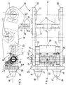
- FIG. 3 is a schematic sectional representation longitudinal of the tool holder of said machine, of which FIG. 4 is a view in cross section.
- Figure 5 is a schematic representation in section longitudinal materializing the attachment of the tool holder on the bucket.
- Figure 6 is a schematic detail representation of the organ locking integral with the tool holder.
- FIG. 1 represents a bucket (1) intended to be adapted to the end of the work equipment of an earth-moving machine, and including what is known as a backhoe.
- This bucket of form known per se, advantageously comprises at the level of its face anterior working teeth (2) brought back by any means.
- the bucket (1) is reversibly attached to the work equipment of said backhoe loader, at the level of the face substantially opposite to the anterior working face, face called in the following description joining face (3).
- housings (6) symmetrically distributed with respect to the plane of symmetry P of the bucket (1), and positioned substantially perpendicular to the bottom of the bucket.
- These housings (6) are biconical in shape, namely a first truncated cone (6a) relatively flared but of low height, extended by a second truncated cone (6b), narrower, but with the same axis of revolution, these two truncated cones joining at a joining area (11).
- the diameter of the junction zone (11) of the two truncated cones is 37 mm.
- the joining face (3) comprises at its other end, two male members, constituted by pins (4), also symmetrically distributed with respect to the plane P of symmetry of the bucket.
- These pins (4) are also of substantially conical shape, and are extended by a base (5), the cones (4) and the base (5) having the same axis of revolution (8).
- the pins (4) are located in a parallel but offset plane relative to the plane containing the housings (6).
- the upper securing face (3) of the bucket also comprises a locking stop (7), described in more detail later in link with figure 6.
- the effective attachment area of the bucket on the tool holder is further delimited by two lateral flanges (10), attached in particular by welding on said upper face (3) of the bucket, and allowing, as will be described later, to facilitate taking automatic tool through the tool holder.
- This tool holder (20) firstly has at one of its ends of the male organs, constituted by nipples (14) of shape general conical extending a base (15), the pins (14) and the base (15) having a symmetry of revolution along the same axis of revolution (18).
- the diameter of the cylindrical base (15) is close to 35 millimeters.
- the base is itself fixed on a support (26) whose function will appear more clearly later.
- the tool holder (20) has a recess in the vicinity of its other end at the level of which are housed housings (16) formed, like the housings (6) of the bucket (1) by two truncated cones of the same axis. of revolution (19), a first truncated cone (16a) of low height but more flared, joining in (17) a second truncated cone (16b), said housings (16) and the pins (14) being symmetrically distributed by relative to the plane of symmetry P ' of the tool holder (20).
- the diameter of the area of junction (17) of the two truncated cones constituting each of the housings is close to 37 millimeters.
- the housings (16) and the nipples (14) are located in two parallel but distinct planes.
- the tool holder (20) further comprises a locking member (21), articulated between the faces (25) of the tool holder, the articulation axis (37) being perpendicular to the plane of symmetry P 'of the holder. tool, and located in the vicinity of the pins (14).
- this locking member (21) firstly comprises a hinge core (32) received in through housings (31) formed for this purpose in the flanges (25) of the tool holder.
- This core (32) receives two parallel flanges (27) formed between the flanges (25) and adjacent thereto, these flanges (27) being substantially directed towards the other end of the tool holder. Between these flanges (27) is mounted a metal plate (28), described in more detail in connection with FIG. 6. This plate (28) is intended to cooperate with the locking stop (7) positioned on the upper face of securing (3) of the bucket (1).
- the core (32) also receives a torsion spring (24), the two free ends (30) come to rest on the top of the flanges (27), and the central zone of which is fixed around a pivot point (22) by means of a bracket (23) secured to the support (26) for a screw (29).
- the spring (24) surrounds the core (32) and exerts, through the ends (30) a torque inducing the rotation of the flanges (27), and starting from the plate (28) in the clockwise in Figure 3.
- FIG. 5 shows the tool holder in place on the bucket, and secured to it reversibly.
- the pins (14) of the tool holder cooperate with the housings (6) of the face upper securing (3) of the bucket, and as a corollary than the nipples (4) of said upper face of the bucket cooperate with the housings (16) of the tool holder (20).
- the axes of revolution (8, 9, 18, 19) of the nipples (4) and (14) respectively on the one hand, and housings (6), (16) on the other hand are not confused but remain parallel and are offset by a distance of about 1 millimeter, the axes respectively (8) and (18) of the nipples being offset from the axes (9) and (19) dwellings relative to a median parallel plane situated between these axes.
- the locking member (21) whose operation will be described below, allows for a game catch-up automatic in particular of the play in the longitudinal direction.
- the plate (28) extends parallel to one of the radial directions emanating from the axis articulation (37). In other words, the median plane of said plate (28) does not join said axis (37).
- the locking stop (7) has a surface of cooperation (40) with cylindrical profile, whose axis of revolution (43) is eccentric with respect to the axis of revolution (37) and in particular located in a higher plane.
- the radius of curvature R 2 of this cylindrical surface (40) is shorter than the radius of curvature R 1 of the circular deflection portion of the end (45) of the plate (28).
- the end (45) of the plate (28) also has a cylindrical profile with the same characteristic that the cylindrical cooperation surface (40) of the stop (7), in other terms, centered on the articulation axis (43).
- the end (45) is simply consists of a slightly rounded dihedral at the level of the junction plane of the two constituent planes of the dihedral.
- the area upper of the cooperation surface (40) of the stop (7) has a step (41) defining a stop (42).
- This stop (42) is intended to cooperate with the end (45) of the plate (28) when the tool holder has been badly secured to the bucket, or to the tool in general.
- this cooperation stop (42) - end (45) of the plate (28) annihilates everything risk of the tool sticking out of the tool holder, even if the tool operation is therefore not satisfactory.
- the noise generated by the game which one cannot in this case overcome, quickly attracts the attention of the operator, who can then carry out a correct re-attachment this time of the tool on the tool holder.
- the tool is detached from the tool holder either manually by means of a lever (35), or hydraulically by the organ bias (not shown), typically consisting of a couple piston - cylinder.
- the automatic setting device thus described allows a drastic reduction of games, especially games longitudinal, by increasing the contact surfaces, this less play leading to less wear on parts giving more safety to the handling of these machines.
Landscapes
- Engineering & Computer Science (AREA)
- Mechanical Engineering (AREA)
- Mining & Mineral Resources (AREA)
- Civil Engineering (AREA)
- General Engineering & Computer Science (AREA)
- Structural Engineering (AREA)
- Component Parts Of Construction Machinery (AREA)
- Earth Drilling (AREA)
- Manipulator (AREA)
- Automatic Tool Replacement In Machine Tools (AREA)
Description
Claims (10)
- Dispositif pour prise automatique d'outil pour engins de terrassement ou analogue comprenant un porte-outil (20) disposé à l'extrémité de l'équipement de travail de l'engin, et dans lequel l'assemblage de l'outil (1) et du porte-outil (20) est réalisé au moyen de deux jeux d'organes mâles et femelles (4, 6, 14, 16) de solidarisation présentant une symétrie de révolution, dont les axes de coopération respectifs (8, 9, 18, 19) des uns avec les autres sont parallèles d'un jeu à l'autre, ledit porte-outil (20) comprenant également un organe de verrouillage (21), destiné à coopérer avec l'outil afin de verrouiller de manière réversible la solidarisation de l'outil avec le porte-outil, caractérisé en ce que l'organe de verrouillage (21) est constitué d'une plaque rigide (28), articulée sur le porte-outil (20) selon un axe d'articulation (37) perpendiculaire à l'axe de révolution (8, 9, 18, 19) des organes de solidarisation (4, 6, 14, 16), ledit axe (37) recevant un ressort de torsion (24) induisant l'abaissement de la plaque (28) contre l'outil (1) et sa coopération avec une butée de verrouillage (7) solidaire dudit outil.
- Dispositif pour prise automatique d'outil selon la revendication 1, caractérisé en ce que la plaque (28) constitutive de l'organe de verrouillage (21) est maintenue par des flasques latéraux (27) articulés sur ledit axe d'articulation (37), l'extrémité (45) de ladite plaque décrivant un arc de cercle centré sur l'axe d'articulation (37) dudit organe de verrouillage, et coopérant par frottement contre la butée de verrouillage (7) au niveau d'une paroi cylindrique (40), dont l'axe de révolution (43) est parallèle à l'axe d'articulation (37) dudit organe de verrouillage mais décentré par rapport à celui-ci, le rayon de courbure R2 de ladite paroi cylindrique (40) étant plus court que le rayon de courbure R1 de l'arc de cercle décrit par l'extrémité (45) de la plaque (28).
- Dispositif pour prise automatique d'outil selon la revendication 2, caractérisé en ce que la plaque (28) s'étend parallèlement à l'une des directions radiales émergeant de l'axe d'articulation (37) de l'organe de verrouillage (21), et se termine par une surface de contact cylindrique (45), dont l'axe de révolution (43) est confondu avec l'axe de révolution de la paroi cylindrique (40) de la butée de verrouillage (7).
- Dispositif pour prise automatique d'outil selon la revendication 2, caractérisé en ce que l'extrémité (45) de ladite plaque (28) est constituée d'un dièdre, dont les deux plans inclinés concourrants, symétriques par rapport à une ligne médiane au niveau de ladite extrémité, intersectent selon une profil arrondi.
- Dispositif pour prise automatique d'outil selon l'une des revendications 1 à 4, caractérisé en ce que la paroi cylindrique (40) de la butée de verrouillage (7) se prolonge au niveau supérieur par un décrochement (41, 42), susceptible de coopérer avec l'extrémité (45) de la plaque (28), notamment en cas de mise en plase imparfaite de l'outil sur le porte-outil.
- Dispositif pour prise automatique d'outil selon l'une des revendications 1 à 5, caractérisé en ce que les organes mâles (4, 14) constitutifs des organes de solidarisation sont de dimensions inférieures à celles des organes femelles (6, 16) avec lesquels ils coopèrent au niveau de leur zone de coopération avec ces derniers, et en ce que, lorsque l'outil (1) est solidarisé au porte-outil (20), les axes de révolution (8, 18) des organes mâles (4, 14) d'un même jeu sont parallèles mais décalés des axes de révolution (9, 19) des organes femelles (6, 16) du jeu correspondant avec lesquels ils coopèrent, la distance séparant chacun des plans contenant les axes de révolution d'un même jeu d'organes mâles étant supérieure à celle séparant chacun des plans contenant les axes de révolution d'un même jeu d'organes femelles.
- Dispositif pour prise automatique d'outil selon la revendication 6, caractérisé en ce que le porte-outil (20) comporte des zones d'appui (26, 36), venant coopérer avec la face de solidarisation (3) de l'outil (1).
- Dispositif pour prise automatique d'outil selon la revendication 7, caractérisé en ce que les zones d'appui (26) prolongent les organes mâles (14) du porte-outil (20), et viennent coopérer par l'intermédiaire de leur face latérale (26a) avec la face de solidarisation (3) de l'outil au voisinage de l'une des extrémités dudit porte-outil (20), et en ce que les zones d'appui (36), de forme sensiblement tronconique, coopèrent avec ladite face de solidarisation (3) de l'outil (1) au voisinage de l'aplomb de l'un des axes d'articalutaion (13) du porte-outil (20) à l'extrémité de l'équipement de travail de l'engin.
- Dispositif pour prise automatique d'outil selon l'une des revendications 6 à 8, caractérisé en ce que les organes mâles sont constitués de tétons (4, 14) de forme tronconique, respectivement un jeu de deux tétons (14) solidaires de la partie amont du porte-outil (20), et un jeu de deux tétons (4), d'axe de révolution (8) parallèle à l'axe de révolution des deux premiers tétons (14), solidaires de la zone postérieure de l'outil (1) et dirigés dans l'autre sens, les organes femelles étant constitués par des logements (6, 16), de forme adaptée à la forme des tétons (4, 14), et respectivement portés sur la zone antérieure de l'outil et la zone postérieure du porte-outil.
- Dispositif pour prise automatique d'outil selon la revendication 9, caractérisé en ce que le diamètre des tétons (4, 14) au niveau de leur zone de coopération avec les logements (6, 16) correspondants est inférieur au diamètre desdits logements au niveau de cette zone.
Applications Claiming Priority (2)
| Application Number | Priority Date | Filing Date | Title |
|---|---|---|---|
| FR9403308 | 1994-03-16 | ||
| FR9403308A FR2717516B1 (fr) | 1994-03-16 | 1994-03-16 | Dispositif pour permettre la prise automatique d'outils, notamment pour engins de terrassement ou analogue. |
Publications (2)
| Publication Number | Publication Date |
|---|---|
| EP0672796A1 EP0672796A1 (fr) | 1995-09-20 |
| EP0672796B1 true EP0672796B1 (fr) | 1999-07-07 |
Family
ID=9461274
Family Applications (1)
| Application Number | Title | Priority Date | Filing Date |
|---|---|---|---|
| EP95420064A Expired - Lifetime EP0672796B1 (fr) | 1994-03-16 | 1995-03-13 | Dispositif pour permettre la prise automatique d'outils, notamment pour engins de terrassement ou analogue |
Country Status (4)
| Country | Link |
|---|---|
| EP (1) | EP0672796B1 (fr) |
| AT (1) | ATE181978T1 (fr) |
| DE (1) | DE69510581T2 (fr) |
| FR (1) | FR2717516B1 (fr) |
Families Citing this family (8)
| Publication number | Priority date | Publication date | Assignee | Title |
|---|---|---|---|---|
| FR2708679B1 (fr) * | 1993-08-06 | 1995-09-01 | Pel Job Groupe | Dispositif pour prise automatique d'outil pour engin de terrassement ou analogue. |
| FR2749332B1 (fr) * | 1996-05-30 | 1998-07-03 | Morin Freres | Dispositif pour fixer un outil a l'extremite du bras d'une pelle mecanique |
| US6163989A (en) * | 1997-03-10 | 2000-12-26 | Clark Equipment Company | Frame for mounting on a boom mounted quick change bracket |
| US5983535A (en) * | 1997-03-10 | 1999-11-16 | Clark Equipment Company | Fastener secured frame for boom mounted quick change bracket |
| US5974706A (en) * | 1997-03-10 | 1999-11-02 | Clark Equipment Company | Attachment construction for earthworking implement |
| AU2001268292A1 (en) * | 2000-06-12 | 2001-12-24 | Clark Equipment Company | Latch bar construction for a quick change bracket |
| DE10028997A1 (de) * | 2000-06-16 | 2001-12-20 | Deere & Co | Anbaurahmen für Vorsatzgeräte einer Arbeitsmaschine und zugehöriger Aufnahmebolzen |
| FR2872231B1 (fr) * | 2004-06-24 | 2006-09-08 | Jean Pierre Dorguin | Dispositif de solidarisation de deux pieces mecaniques |
Family Cites Families (3)
| Publication number | Priority date | Publication date | Assignee | Title |
|---|---|---|---|---|
| FR2475160A1 (fr) * | 1980-01-31 | 1981-08-07 | Pingon Pierre De | Dispositif formant prise d'outils automatique pour excavateur, chargeur, machine de terrassement ou autres |
| DE4026210C2 (de) * | 1990-08-18 | 1994-08-11 | Ahlmann Maschinenbau Gmbh | Schnellwechselvorrichtung |
| FR2690718B1 (fr) * | 1992-05-04 | 1994-06-17 | Groupe Pel Job | Dispositif de securite pour prise automatique d'outils, en particulier pour machines de terrassement ou analogue. |
-
1994
- 1994-03-16 FR FR9403308A patent/FR2717516B1/fr not_active Expired - Lifetime
-
1995
- 1995-03-13 EP EP95420064A patent/EP0672796B1/fr not_active Expired - Lifetime
- 1995-03-13 AT AT95420064T patent/ATE181978T1/de active
- 1995-03-13 DE DE69510581T patent/DE69510581T2/de not_active Expired - Lifetime
Also Published As
| Publication number | Publication date |
|---|---|
| FR2717516B1 (fr) | 1996-05-03 |
| EP0672796A1 (fr) | 1995-09-20 |
| DE69510581D1 (de) | 1999-08-12 |
| FR2717516A1 (fr) | 1995-09-22 |
| ATE181978T1 (de) | 1999-07-15 |
| DE69510581T2 (de) | 1999-11-18 |
Similar Documents
| Publication | Publication Date | Title |
|---|---|---|
| EP0196263B1 (fr) | Machine agricole à dispositif de transmission perfectionné | |
| EP1486620B1 (fr) | Outil de fraisage pour la réalisation de tranchées, permettant un changement rapide de la tête de coupe | |
| EP2788551B1 (fr) | Systeme mecanique comprenant une piece d'usure et un support, et godet comprenant au moins un tel systeme mecanique | |
| FR2549911A1 (fr) | Dispositif a piece d'usure pour machine de terrassement | |
| FR2475160A1 (fr) | Dispositif formant prise d'outils automatique pour excavateur, chargeur, machine de terrassement ou autres | |
| FR2979648A1 (fr) | Systeme mecanique comprenant un dispositif de liaison entre une piece d'usure et son support, godet d'engin de travaux publics et procede de mise en oeuvre d'un tel systeme | |
| EP0672796A1 (fr) | Dispositif pour permettre la prise automatique d'outils, notamment pour engins de terrassement ou analogue | |
| CA2410521C (fr) | Tete a aleser | |
| CA2596820A1 (fr) | Appareil de damage destine a etre associe a un brise-roche | |
| FR2769789A1 (fr) | Dispositif de relevage, en particulier de relevage avant, pour tracteur agricole ou analogue | |
| EP0594486B1 (fr) | Dispositif d'attache rapide pour équipement d'engin de génie civil et de manutention | |
| EP0943708B1 (fr) | Mécanisme de tirage pour mécanique d'armure et métier à tisser comprenant un tel mécanisme de tirage | |
| EP1452749B1 (fr) | Dispositif de jonction articulée | |
| FR3096420A1 (fr) | Dispositif d’accouplement de deux arbres et dispositif d’attelage muni d’un tel dispositif d’accouplement | |
| EP0026131A1 (fr) | Suspension à jambe télescopique oscillante pour roue de véhicule | |
| FR2793379A1 (fr) | Dispositif d'adaptation pour barre d'attelage de tracteur | |
| CH681071A5 (fr) | ||
| EP0378485B1 (fr) | Dispositif de fixation des tambours de fraisage sur un appareil destiné à creuser des tranchées dans le sol | |
| FR2701047A1 (fr) | Système universel de liaison pour la solidarisation d'un accessoire, notamment d'un godet ou d'une benne, au bras articulé d'un engin de travaux publics. | |
| FR2690718A1 (fr) | Dispositif de sécurité pour prise automatique d'outils, en particulier pour machines de terrassement ou analogue. | |
| EP0891687B1 (fr) | Outil amovible pour machine de travail du sol | |
| EP0498732B1 (fr) | Ensemble outil et porte-outil pour machine de creusement de tunnels et galeries | |
| EP1896663A1 (fr) | Support d articulation pour outils d engin de travaux, constituant une attache rapide et procede de fabrication associe | |
| CA1254757A (fr) | Dispositif d'accouplement a denture pour arbres oscillants | |
| FR2629114A1 (fr) | Vehicule pour travaux de terrassement |
Legal Events
| Date | Code | Title | Description |
|---|---|---|---|
| PUAI | Public reference made under article 153(3) epc to a published international application that has entered the european phase |
Free format text: ORIGINAL CODE: 0009012 |
|
| AK | Designated contracting states |
Kind code of ref document: A1 Designated state(s): AT BE CH DE DK ES FR GB GR IE IT LI LU MC NL PT SE |
|
| 17P | Request for examination filed |
Effective date: 19960124 |
|
| GRAG | Despatch of communication of intention to grant |
Free format text: ORIGINAL CODE: EPIDOS AGRA |
|
| GRAG | Despatch of communication of intention to grant |
Free format text: ORIGINAL CODE: EPIDOS AGRA |
|
| GRAH | Despatch of communication of intention to grant a patent |
Free format text: ORIGINAL CODE: EPIDOS IGRA |
|
| 17Q | First examination report despatched |
Effective date: 19990223 |
|
| GRAH | Despatch of communication of intention to grant a patent |
Free format text: ORIGINAL CODE: EPIDOS IGRA |
|
| GRAA | (expected) grant |
Free format text: ORIGINAL CODE: 0009210 |
|
| AK | Designated contracting states |
Kind code of ref document: B1 Designated state(s): AT BE CH DE DK ES FR GB GR IE IT LI LU MC NL PT SE |
|
| PG25 | Lapsed in a contracting state [announced via postgrant information from national office to epo] |
Ref country code: SE Free format text: THE PATENT HAS BEEN ANNULLED BY A DECISION OF A NATIONAL AUTHORITY Effective date: 19990707 Ref country code: NL Free format text: LAPSE BECAUSE OF FAILURE TO SUBMIT A TRANSLATION OF THE DESCRIPTION OR TO PAY THE FEE WITHIN THE PRESCRIBED TIME-LIMIT Effective date: 19990707 Ref country code: GR Free format text: LAPSE BECAUSE OF NON-PAYMENT OF DUE FEES Effective date: 19990707 Ref country code: ES Free format text: THE PATENT HAS BEEN ANNULLED BY A DECISION OF A NATIONAL AUTHORITY Effective date: 19990707 Ref country code: AT Free format text: LAPSE BECAUSE OF FAILURE TO SUBMIT A TRANSLATION OF THE DESCRIPTION OR TO PAY THE FEE WITHIN THE PRESCRIBED TIME-LIMIT Effective date: 19990707 |
|
| REF | Corresponds to: |
Ref document number: 181978 Country of ref document: AT Date of ref document: 19990715 Kind code of ref document: T |
|
| REG | Reference to a national code |
Ref country code: CH Ref legal event code: EP |
|
| REF | Corresponds to: |
Ref document number: 69510581 Country of ref document: DE Date of ref document: 19990812 |
|
| GBT | Gb: translation of ep patent filed (gb section 77(6)(a)/1977) |
Effective date: 19990803 |
|
| REG | Reference to a national code |
Ref country code: IE Ref legal event code: FG4D Free format text: FRENCH |
|
| ITF | It: translation for a ep patent filed | ||
| PG25 | Lapsed in a contracting state [announced via postgrant information from national office to epo] |
Ref country code: PT Free format text: LAPSE BECAUSE OF FAILURE TO SUBMIT A TRANSLATION OF THE DESCRIPTION OR TO PAY THE FEE WITHIN THE PRESCRIBED TIME-LIMIT Effective date: 19991007 Ref country code: DK Free format text: LAPSE BECAUSE OF FAILURE TO SUBMIT A TRANSLATION OF THE DESCRIPTION OR TO PAY THE FEE WITHIN THE PRESCRIBED TIME-LIMIT Effective date: 19991007 |
|
| NLV1 | Nl: lapsed or annulled due to failure to fulfill the requirements of art. 29p and 29m of the patents act | ||
| REG | Reference to a national code |
Ref country code: FR Ref legal event code: CD |
|
| PG25 | Lapsed in a contracting state [announced via postgrant information from national office to epo] |
Ref country code: LU Free format text: LAPSE BECAUSE OF NON-PAYMENT OF DUE FEES Effective date: 20000313 |
|
| RAP2 | Party data changed (patent owner data changed or rights of a patent transferred) |
Owner name: VOLVO COMPACT EQUIPMENT S.A. |
|
| PG25 | Lapsed in a contracting state [announced via postgrant information from national office to epo] |
Ref country code: LI Free format text: LAPSE BECAUSE OF NON-PAYMENT OF DUE FEES Effective date: 20000331 Ref country code: CH Free format text: LAPSE BECAUSE OF NON-PAYMENT OF DUE FEES Effective date: 20000331 Ref country code: BE Free format text: LAPSE BECAUSE OF NON-PAYMENT OF DUE FEES Effective date: 20000331 |
|
| PLBE | No opposition filed within time limit |
Free format text: ORIGINAL CODE: 0009261 |
|
| STAA | Information on the status of an ep patent application or granted ep patent |
Free format text: STATUS: NO OPPOSITION FILED WITHIN TIME LIMIT |
|
| 26N | No opposition filed | ||
| PG25 | Lapsed in a contracting state [announced via postgrant information from national office to epo] |
Ref country code: IE Free format text: LAPSE BECAUSE OF NON-PAYMENT OF DUE FEES Effective date: 20000719 |
|
| REG | Reference to a national code |
Ref country code: IE Ref legal event code: FD4D |
|
| BERE | Be: lapsed |
Owner name: GROUPE PEL-JOB Effective date: 20000331 |
|
| PG25 | Lapsed in a contracting state [announced via postgrant information from national office to epo] |
Ref country code: MC Free format text: LAPSE BECAUSE OF NON-PAYMENT OF DUE FEES Effective date: 20000930 |
|
| REG | Reference to a national code |
Ref country code: CH Ref legal event code: PL |
|
| REG | Reference to a national code |
Ref country code: GB Ref legal event code: IF02 |
|
| PGFP | Annual fee paid to national office [announced via postgrant information from national office to epo] |
Ref country code: FR Payment date: 20140311 Year of fee payment: 20 Ref country code: IT Payment date: 20140320 Year of fee payment: 20 |
|
| PGFP | Annual fee paid to national office [announced via postgrant information from national office to epo] |
Ref country code: GB Payment date: 20140312 Year of fee payment: 20 |
|
| PGFP | Annual fee paid to national office [announced via postgrant information from national office to epo] |
Ref country code: DE Payment date: 20140417 Year of fee payment: 20 |
|
| REG | Reference to a national code |
Ref country code: DE Ref legal event code: R071 Ref document number: 69510581 Country of ref document: DE |
|
| REG | Reference to a national code |
Ref country code: GB Ref legal event code: PE20 Expiry date: 20150312 |
|
| PG25 | Lapsed in a contracting state [announced via postgrant information from national office to epo] |
Ref country code: GB Free format text: LAPSE BECAUSE OF EXPIRATION OF PROTECTION Effective date: 20150312 |