EP0671592A2 - Luftleitung mit Auslass zum Zuführen von strömendem Fluid, insbesondere für private oder gewerbliche Räume - Google Patents
Luftleitung mit Auslass zum Zuführen von strömendem Fluid, insbesondere für private oder gewerbliche Räume Download PDFInfo
- Publication number
- EP0671592A2 EP0671592A2 EP95102904A EP95102904A EP0671592A2 EP 0671592 A2 EP0671592 A2 EP 0671592A2 EP 95102904 A EP95102904 A EP 95102904A EP 95102904 A EP95102904 A EP 95102904A EP 0671592 A2 EP0671592 A2 EP 0671592A2
- Authority
- EP
- European Patent Office
- Prior art keywords
- fluid
- duct
- slits
- duct according
- delivery outlet
- Prior art date
- Legal status (The legal status is an assumption and is not a legal conclusion. Google has not performed a legal analysis and makes no representation as to the accuracy of the status listed.)
- Granted
Links
Images
Classifications
-
- F—MECHANICAL ENGINEERING; LIGHTING; HEATING; WEAPONS; BLASTING
- F24—HEATING; RANGES; VENTILATING
- F24F—AIR-CONDITIONING; AIR-HUMIDIFICATION; VENTILATION; USE OF AIR CURRENTS FOR SCREENING
- F24F13/00—Details common to, or for air-conditioning, air-humidification, ventilation or use of air currents for screening
- F24F13/02—Ducting arrangements
- F24F13/0218—Flexible soft ducts, e.g. ducts made of permeable textiles
-
- F—MECHANICAL ENGINEERING; LIGHTING; HEATING; WEAPONS; BLASTING
- F24—HEATING; RANGES; VENTILATING
- F24F—AIR-CONDITIONING; AIR-HUMIDIFICATION; VENTILATION; USE OF AIR CURRENTS FOR SCREENING
- F24F13/00—Details common to, or for air-conditioning, air-humidification, ventilation or use of air currents for screening
- F24F13/02—Ducting arrangements
-
- F—MECHANICAL ENGINEERING; LIGHTING; HEATING; WEAPONS; BLASTING
- F24—HEATING; RANGES; VENTILATING
- F24F—AIR-CONDITIONING; AIR-HUMIDIFICATION; VENTILATION; USE OF AIR CURRENTS FOR SCREENING
- F24F13/00—Details common to, or for air-conditioning, air-humidification, ventilation or use of air currents for screening
- F24F13/02—Ducting arrangements
- F24F13/06—Outlets for directing or distributing air into rooms or spaces, e.g. ceiling air diffuser
-
- F—MECHANICAL ENGINEERING; LIGHTING; HEATING; WEAPONS; BLASTING
- F24—HEATING; RANGES; VENTILATING
- F24F—AIR-CONDITIONING; AIR-HUMIDIFICATION; VENTILATION; USE OF AIR CURRENTS FOR SCREENING
- F24F13/00—Details common to, or for air-conditioning, air-humidification, ventilation or use of air currents for screening
- F24F13/02—Ducting arrangements
- F24F13/06—Outlets for directing or distributing air into rooms or spaces, e.g. ceiling air diffuser
- F24F2013/0608—Perforated ducts
Definitions
- the present invention relates to a duct with outlets for delivering a conveyed fluid, particularly for systems for air-conditioning civil or industrial premises.
- For conditioning civil or industrial premises ducts are used, which are embedded in the masonry of the buildings or placed outside the masonry, and by means of which the conditioning fluid, constituted by hot or cold air, is conveyed and distributed in the various areas of the rooms to be conditioned.
- ducts which are constituted by tubes made of resin-treated fabric, are suspended at a certain height from the floor of the room, and have, along their extension, multiple fluid delivery outlets which are spaced one from another according to the requirements of the distribution of the fluid within the room.
- Said delivery outlets are generally constituted by circular or square holes which are obtained by removing portions of the walls of the tubular body made of resin-treated fabric.
- the delivery outlets have a fluid passage section that is constant and independent of the variation in the difference in pressure between the fluid inside the duct and the outside. Due to this fact, the conditions at which the fluid is delivered vary as the pressure of the fluid inside the duct varies. High pressures and high flow-rates of the fluid conveyed along the duct in fact lead to high speeds of the fluid delivered through the outlets; such speeds can be unpleasant for the occupants of the space being air-conditioned. On the other hand, this problem is not easy to solve since operating with larger outlets, which would have the advantage of reducing the fluid delivery speed, would cause the drawback of eliminating the effects of conditioning when the system must operate at low flow-rates and low pressures.
- a principal aim of the present invention is to solve the drawbacks described above, providing a duct with delivery outlets that allow to deliver high fluid flow-rates but with very low pressure losses and thus with reduced energy consumption with respect to known ducts.
- an object of the invention is to provide a duct with delivery outlets that is capable of reducing the fluid delivery speed at high flow-rates without however eliminating the effects of delivery at low flow-rates.
- Another object of the invention is to provide a duct with delivery outlets that allow, if required, a particular orientation of the delivered fluid.
- a duct with outlets for delivering the conveyed fluid particularly for systems for air-conditioning civil or industrial premises, which comprises a hollow body that can be connected to a source of pressurized fluid and has, along its extension, at least one outlet for delivering said fluid, characterized in that said delivery outlet is delimited, along at least one of its sides, by a flap that can flex elastically due to the action of said fluid to vary the passage section of the fluid through said delivery outlet as the difference in pressure between the inside of said hollow body and the outside varies.
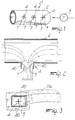
- the duct according to the invention comprises a hollow body 2 which can be connected in a per se known manner to a source of pressurized fluid, such as for example a pump 3, by means of which the fluid to be conveyed is fed into the hollow body 2.
- a source of pressurized fluid such as for example a pump 3
- the duct there is at least one delivery outlet 4 through which the fluid conveyed inside the hollow body 2 is delivered outside.
- said delivery outlet 4 is delimited, along at least one of its sides, by a flap that can flex elastically by virtue of the action of the fluid conveyed in the hollow body 2 in order to vary the passage section of the fluid through the delivery outlet as the difference in pressure between the inside of the duct and the outside varies.
- the hollow body can be constituted by a tubular body made of resin-treated fabric, as shown in particular in figures 1 and 2, or can be constituted by a rigid body, designated by the reference numeral 2a in figure 3.
- the hollow body has at least one portion that is made of elastically flexible material, and the delivery outlet is formed exactly in this portion made of elastically flexible material.
- the hollow body is constituted by a tubular body made of resin-treated fabric, elastic flexibility is ensured by the very material of which the hollow body is made, whereas if the hollow body is constituted by a rigid tubular body, a portion 5, constituted for example by a sheet made of elastically flexible material in which the delivery outlet is formed, will be provided.
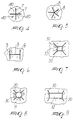
- the delivery outlet is formed by slits which are formed directly in the walls of the hollow body 2, if said body is made of elastically flexible material, or are formed in the portion 5 made of elastically flexible material which is applied to the hollow body 2a.
- These slits in practice form the delivery outlet with one or more perimetric elastically flexible flaps 40.
- the slits may have various shapes and arrangements according to the requirements.
- the delivery outlet can be formed by slits 7 and 8 that extend from a same point and are distributed symmetrically around said point.
- the slits 9 can also be arranged symmetrically with respect to an axis rather than a point.
- the slits 30 can start from a hole 10, 11, and 12 rather than from a point, and the hole may be circular, square, rectangular, and so forth.
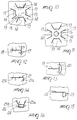
- Figure 10 illustrates a further embodiment of the outlet in the duct according to the invention.
- the outlet is formed by slits 13 which delimit sector-like flaps 14 that extend radially outwards from a circular region 15.
- Figure 11 illustrates still a further different embodiment, similar to the one shown in the preceding figure, in which a hole 16 is formed in the circular region 15.
- Figure 12 illustrates another different embodiment of the outlet in the duct according to the invention, wherein the outlet is formed by two slits 17 and 18, one of which starts from the median point of the other.
- the outlet is formed by a slit 19 that runs from a median region of the straight side of a hole 20 shaped like a circular portion.
- Figure 14 illustrates an outlet which is simply constituted by a slit 21 with two portions 21a and 21b lying at right angles to each other.
- Figure 15 illustrates an outlet which is constituted by a slit 22 that extends from the base of a rectangular hole 23.
- Figure 16 illustrates an outlet which is constituted by a rectangular hole 24 with a flap formed by two slits 25a and 25b which run from two vertices of the hole 24 and delimit a flap 26 that affects a single side of the hole.
- Figures 12 to 16 illustrate outlets which are constituted by slits which are asymmetrical, so as to obtain a different deformability of the sides of the outlet as the pressure of the fluid conveyed inside the duct varies.
- the slits that form the delivery outlets can be provided using known technologies, such as for example punching, laser cutting, melting, molding, blanking, coupling, etcetera.
- the outlets of the duct according to the invention can vary, by virtue of the elastic flexibility of the flap or flaps which are formed by the slits and affect one or more of their sides, the passage section of the fluid during delivery according to the difference in pressure between the fluid inside the duct and the outside.
- the delivery outlet under the thrust of the fluid itself, assumes the condition in which its passage section is largest, thus reducing the speed at which the fluid is delivered and avoiding unpleasant effects on the occupants of the air-conditioned space.
- the delivery outlet can have a reduced fluid passage section, so as to still allow the delivered fluid to reach the desired distances from the duct.
- the duct with delivery outlets according to the invention fully achieves the intended aim, since it automatically modulates the delivery speed of the fluid, reducing pressure losses at the delivery outlets, and thus reducing the energy consumption required to convey and distribute the fluid.
- a further advantage of the duct with delivery outlets according to the invention is that it is possible to shape the outlets so that the configuration of the outlet varies as the pressure of the fluid inside the duct varies, thus allowing to orientate as required the flow of the fluid that leaves the duct.
- the duct with delivery outlets according to the invention has been conceived in particular for systems for air-conditioning civil or industrial premises, it can nonetheless also be used for conveying and distributing any type of fluid in the gaseous or liquid phase or in a mixed liquid-gaseous phase at any temperature and pressure.
- the materials employed, as well as the contingent shapes and dimensions may be any according to the requirements and the state of the art.
Landscapes
- Engineering & Computer Science (AREA)
- Chemical & Material Sciences (AREA)
- Combustion & Propulsion (AREA)
- Mechanical Engineering (AREA)
- General Engineering & Computer Science (AREA)
- Textile Engineering (AREA)
- Duct Arrangements (AREA)
- Other Air-Conditioning Systems (AREA)
- Nozzles (AREA)
- Rigid Pipes And Flexible Pipes (AREA)
- Fertilizers (AREA)
Applications Claiming Priority (2)
| Application Number | Priority Date | Filing Date | Title |
|---|---|---|---|
| ITMI940432A IT1270028B (it) | 1994-03-09 | 1994-03-09 | Conduttura con bocchette di erogazione del fluido trasportato, particolarmente per impianti per il condizionamento di ambienti civilio industriali |
| ITMI940432 | 1994-03-09 |
Publications (3)
| Publication Number | Publication Date |
|---|---|
| EP0671592A2 true EP0671592A2 (de) | 1995-09-13 |
| EP0671592A3 EP0671592A3 (de) | 1996-02-07 |
| EP0671592B1 EP0671592B1 (de) | 2000-11-15 |
Family
ID=11368131
Family Applications (1)
| Application Number | Title | Priority Date | Filing Date |
|---|---|---|---|
| EP95102904A Expired - Lifetime EP0671592B1 (de) | 1994-03-09 | 1995-03-01 | Luftleitung mit Auslass zum Zuführen von strömendem Fluid, insbesondere für private oder gewerbliche Räume |
Country Status (6)
| Country | Link |
|---|---|
| US (1) | US5649860A (de) |
| EP (1) | EP0671592B1 (de) |
| CA (1) | CA2144131C (de) |
| DE (1) | DE69519396T2 (de) |
| ES (1) | ES2152336T3 (de) |
| IT (1) | IT1270028B (de) |
Cited By (4)
| Publication number | Priority date | Publication date | Assignee | Title |
|---|---|---|---|---|
| CH699655A1 (de) * | 2008-10-10 | 2010-04-15 | Oekag Wassertechnik Schweiz Ag | Vorrichtung zum Zurückhalten aufsteigender Warmluft. |
| EP2354696A3 (de) * | 2010-01-22 | 2014-07-02 | KE Fibertec A/S | Direktionale durchflussgesteuerte Luftleitung |
| ITMI20131607A1 (it) * | 2013-09-30 | 2015-03-31 | D C S Tek S R L | Canalizzazione con ugelli ad erogazione dinamica del fluido trasportato |
| ITUA20162075A1 (it) * | 2016-03-29 | 2017-09-29 | Anna Faverio | Condizionatore dell’aria con strisce pieghevoli |
Families Citing this family (11)
| Publication number | Priority date | Publication date | Assignee | Title |
|---|---|---|---|---|
| US6117005A (en) * | 1998-12-03 | 2000-09-12 | Weiss; Peter T. | Air conditioning extender system |
| US6488219B1 (en) * | 1999-07-21 | 2002-12-03 | D. Scott Herr | Steam humidifier with pressure variable aperture |
| US20060064125A1 (en) * | 2001-05-09 | 2006-03-23 | James Henderson | Button anchor system for moving tissue |
| US20050062284A1 (en) * | 2003-08-25 | 2005-03-24 | Juergen Schreiner | Pressure relief valve in connector assembly of inflatable articles |
| US20050046182A1 (en) * | 2003-08-25 | 2005-03-03 | Trapp Benjamin M. | Connector assembly for flexible inflatable articles |
| US20060252365A1 (en) * | 2005-05-04 | 2006-11-09 | Gebke Kevin J | Pliable air duct with pressure responsive discharge outlets |
| GB0603969D0 (en) * | 2006-02-28 | 2006-04-05 | Eaton Williams Group Ltd | A humidifier unit |
| US20080176506A1 (en) * | 2007-01-22 | 2008-07-24 | Rite-Hite Holding Corporation | Fabric diffuser with programmed airflow |
| US20120028562A1 (en) * | 2010-07-27 | 2012-02-02 | Frank Heim | Flexible air ducts with gradual inflation |
| DE102013216127B4 (de) * | 2013-08-14 | 2015-03-19 | Eberspächer Climate Control Systems GmbH & Co. KG | Strömungsverdämmungselement, insbesondere zur Luftströmungsverdämmung in einem Luftkanalsystem eines Fahrzeugs |
| DE102019005728B4 (de) * | 2019-08-16 | 2022-01-20 | Daimler Ag | Belüftungsvorrichtung für einen Kraftwagen, insbesondere für einen Personenkraftwagen, sowie Kraftwagen mit einer solchen Belüftungsvorrichtung |
Family Cites Families (11)
| Publication number | Priority date | Publication date | Assignee | Title |
|---|---|---|---|---|
| DE216078C (de) * | ||||
| DE916249C (de) * | 1952-10-14 | 1954-08-05 | Jos Muesch & Co G M B H | Schlauch mit Austrittsoeffnungen in seinem Mantel |
| GB929285A (en) * | 1959-06-09 | 1963-06-19 | Activair Ltd | Air ducting system |
| US3120167A (en) * | 1962-03-19 | 1964-02-04 | Hudson Inst | Shelter ventilation system |
| GB1111261A (en) * | 1965-03-24 | 1968-04-24 | A I R Air Conditioning And Ref | Improvements in ventilating systems |
| FR1527197A (fr) * | 1967-04-21 | 1968-05-31 | Rech S De Ventilation Et D Aer | Diffuseur régulateur de débit destiné, notamment à l'admission d'air frais dans les locaux d'habitation |
| US3733854A (en) * | 1971-12-23 | 1973-05-22 | North American Rockwell | Shielded angular drive transmitting joint and shielded quickly detachable coupling thereof |
| FR2185150A5 (de) * | 1972-05-18 | 1973-12-28 | Dubois Jacques | |
| FI750505A7 (de) * | 1975-02-24 | 1976-08-25 | Veikko Kalevi Sassi | |
| DE2508865A1 (de) * | 1975-02-28 | 1976-09-16 | Irja Lehto | Bewaesserungsrohr |
| US5044259A (en) * | 1989-10-23 | 1991-09-03 | Dynaforce Corporation | Air diffusion system capable of limited area control and adapted for supplying make-up air to an enclosure |
-
1994
- 1994-03-09 IT ITMI940432A patent/IT1270028B/it active IP Right Grant
-
1995
- 1995-02-28 US US08/396,388 patent/US5649860A/en not_active Expired - Lifetime
- 1995-03-01 DE DE69519396T patent/DE69519396T2/de not_active Expired - Fee Related
- 1995-03-01 EP EP95102904A patent/EP0671592B1/de not_active Expired - Lifetime
- 1995-03-01 ES ES95102904T patent/ES2152336T3/es not_active Expired - Lifetime
- 1995-03-07 CA CA002144131A patent/CA2144131C/en not_active Expired - Fee Related
Cited By (4)
| Publication number | Priority date | Publication date | Assignee | Title |
|---|---|---|---|---|
| CH699655A1 (de) * | 2008-10-10 | 2010-04-15 | Oekag Wassertechnik Schweiz Ag | Vorrichtung zum Zurückhalten aufsteigender Warmluft. |
| EP2354696A3 (de) * | 2010-01-22 | 2014-07-02 | KE Fibertec A/S | Direktionale durchflussgesteuerte Luftleitung |
| ITMI20131607A1 (it) * | 2013-09-30 | 2015-03-31 | D C S Tek S R L | Canalizzazione con ugelli ad erogazione dinamica del fluido trasportato |
| ITUA20162075A1 (it) * | 2016-03-29 | 2017-09-29 | Anna Faverio | Condizionatore dell’aria con strisce pieghevoli |
Also Published As
| Publication number | Publication date |
|---|---|
| ITMI940432A0 (it) | 1994-03-09 |
| US5649860A (en) | 1997-07-22 |
| EP0671592B1 (de) | 2000-11-15 |
| EP0671592A3 (de) | 1996-02-07 |
| ITMI940432A1 (it) | 1995-09-09 |
| CA2144131C (en) | 2006-11-14 |
| DE69519396D1 (de) | 2000-12-21 |
| CA2144131A1 (en) | 1995-09-10 |
| IT1270028B (it) | 1997-04-28 |
| DE69519396T2 (de) | 2001-06-13 |
| ES2152336T3 (es) | 2001-02-01 |
Similar Documents
| Publication | Publication Date | Title |
|---|---|---|
| EP0671592B1 (de) | Luftleitung mit Auslass zum Zuführen von strömendem Fluid, insbesondere für private oder gewerbliche Räume | |
| US6565430B2 (en) | Pliable air duct with dust and condensation repellency | |
| US20060252365A1 (en) | Pliable air duct with pressure responsive discharge outlets | |
| US6280320B1 (en) | Frame to support a deflated fabric air duct | |
| US9709193B2 (en) | Pliable air ducts with anti-condensation nozzles | |
| US6626754B2 (en) | Conical air filter | |
| US4531454A (en) | Air conditioning system | |
| CA2252351A1 (en) | Variable air volume control system | |
| EP2354696B1 (de) | Direktionale durchflussgesteuerte Luftleitung | |
| US6595848B1 (en) | Static air mixing apparatus | |
| EP0985890A4 (de) | Innenraumeinheit einer klimaanlage und vorrichtung zu dessen einbau | |
| US3927827A (en) | Method for controlling the ventilation of an air-conditioning system | |
| IT1295431B1 (it) | Condizionatore d'aria avente pale di controllo di direzione di aria girevoli | |
| US5948509A (en) | Non collapsing pre-assembled flexible duct connector | |
| GB2121879A (en) | Blowers for air conditioning plant | |
| KR20000074857A (ko) | 형상기억합금을 이용한 가변형 자동 디퓨져 | |
| EP0146485B1 (de) | Balganordnung | |
| EP0608350B1 (de) | Vorrichtung zum steuern der luftströmung | |
| JP3128441B2 (ja) | 空気調和機 | |
| JP2771560B2 (ja) | アンダーフロアー空調設備 | |
| JPH11173641A (ja) | ダクト式空気調和機 | |
| FR2451550A1 (fr) | Procede pour la climatisation d'un local par amenee d'air et installation d'aeration pour la realisation de ce procede | |
| JPS6435350U (de) | ||
| Redding et al. | Breathing space | |
| FI71419C (fi) | Inblaosningsorgan foer tillfoersel av luft |
Legal Events
| Date | Code | Title | Description |
|---|---|---|---|
| PUAI | Public reference made under article 153(3) epc to a published international application that has entered the european phase |
Free format text: ORIGINAL CODE: 0009012 |
|
| AK | Designated contracting states |
Kind code of ref document: A2 Designated state(s): BE DE ES FR GB GR LU NL |
|
| PUAL | Search report despatched |
Free format text: ORIGINAL CODE: 0009013 |
|
| AK | Designated contracting states |
Kind code of ref document: A3 Designated state(s): BE DE ES FR GB GR LU NL |
|
| 17P | Request for examination filed |
Effective date: 19960710 |
|
| 17Q | First examination report despatched |
Effective date: 19980317 |
|
| GRAG | Despatch of communication of intention to grant |
Free format text: ORIGINAL CODE: EPIDOS AGRA |
|
| GRAG | Despatch of communication of intention to grant |
Free format text: ORIGINAL CODE: EPIDOS AGRA |
|
| GRAH | Despatch of communication of intention to grant a patent |
Free format text: ORIGINAL CODE: EPIDOS IGRA |
|
| GRAH | Despatch of communication of intention to grant a patent |
Free format text: ORIGINAL CODE: EPIDOS IGRA |
|
| GRAA | (expected) grant |
Free format text: ORIGINAL CODE: 0009210 |
|
| AK | Designated contracting states |
Kind code of ref document: B1 Designated state(s): BE DE ES FR GB GR LU NL |
|
| PG25 | Lapsed in a contracting state [announced via postgrant information from national office to epo] |
Ref country code: NL Free format text: LAPSE BECAUSE OF FAILURE TO SUBMIT A TRANSLATION OF THE DESCRIPTION OR TO PAY THE FEE WITHIN THE PRESCRIBED TIME-LIMIT Effective date: 20001115 Ref country code: GR Free format text: LAPSE BECAUSE OF NON-PAYMENT OF DUE FEES Effective date: 20001115 Ref country code: BE Free format text: LAPSE BECAUSE OF FAILURE TO SUBMIT A TRANSLATION OF THE DESCRIPTION OR TO PAY THE FEE WITHIN THE PRESCRIBED TIME-LIMIT Effective date: 20001115 |
|
| REF | Corresponds to: |
Ref document number: 69519396 Country of ref document: DE Date of ref document: 20001221 |
|
| REG | Reference to a national code |
Ref country code: ES Ref legal event code: FG2A Ref document number: 2152336 Country of ref document: ES Kind code of ref document: T3 |
|
| ET | Fr: translation filed | ||
| PG25 | Lapsed in a contracting state [announced via postgrant information from national office to epo] |
Ref country code: LU Free format text: LAPSE BECAUSE OF NON-PAYMENT OF DUE FEES Effective date: 20010301 |
|
| NLV1 | Nl: lapsed or annulled due to failure to fulfill the requirements of art. 29p and 29m of the patents act | ||
| PLBE | No opposition filed within time limit |
Free format text: ORIGINAL CODE: 0009261 |
|
| STAA | Information on the status of an ep patent application or granted ep patent |
Free format text: STATUS: NO OPPOSITION FILED WITHIN TIME LIMIT |
|
| 26N | No opposition filed | ||
| REG | Reference to a national code |
Ref country code: GB Ref legal event code: IF02 |
|
| PGFP | Annual fee paid to national office [announced via postgrant information from national office to epo] |
Ref country code: GB Payment date: 20090928 Year of fee payment: 15 |
|
| PGFP | Annual fee paid to national office [announced via postgrant information from national office to epo] |
Ref country code: ES Payment date: 20090930 Year of fee payment: 15 Ref country code: DE Payment date: 20090930 Year of fee payment: 15 |
|
| PGFP | Annual fee paid to national office [announced via postgrant information from national office to epo] |
Ref country code: FR Payment date: 20091016 Year of fee payment: 15 |
|
| GBPC | Gb: european patent ceased through non-payment of renewal fee |
Effective date: 20100301 |
|
| REG | Reference to a national code |
Ref country code: FR Ref legal event code: ST Effective date: 20101130 |
|
| PG25 | Lapsed in a contracting state [announced via postgrant information from national office to epo] |
Ref country code: FR Free format text: LAPSE BECAUSE OF NON-PAYMENT OF DUE FEES Effective date: 20100331 |
|
| PG25 | Lapsed in a contracting state [announced via postgrant information from national office to epo] |
Ref country code: DE Free format text: LAPSE BECAUSE OF NON-PAYMENT OF DUE FEES Effective date: 20101001 |
|
| PG25 | Lapsed in a contracting state [announced via postgrant information from national office to epo] |
Ref country code: GB Free format text: LAPSE BECAUSE OF NON-PAYMENT OF DUE FEES Effective date: 20100301 |
|
| REG | Reference to a national code |
Ref country code: ES Ref legal event code: FD2A Effective date: 20110418 |
|
| PG25 | Lapsed in a contracting state [announced via postgrant information from national office to epo] |
Ref country code: ES Free format text: LAPSE BECAUSE OF NON-PAYMENT OF DUE FEES Effective date: 20110404 |
|
| PG25 | Lapsed in a contracting state [announced via postgrant information from national office to epo] |
Ref country code: ES Free format text: LAPSE BECAUSE OF NON-PAYMENT OF DUE FEES Effective date: 20100302 |