EP0670796B1 - Auswuchtgewichteinrichtung eines rotorblattes - Google Patents
Auswuchtgewichteinrichtung eines rotorblattes Download PDFInfo
- Publication number
- EP0670796B1 EP0670796B1 EP94902419A EP94902419A EP0670796B1 EP 0670796 B1 EP0670796 B1 EP 0670796B1 EP 94902419 A EP94902419 A EP 94902419A EP 94902419 A EP94902419 A EP 94902419A EP 0670796 B1 EP0670796 B1 EP 0670796B1
- Authority
- EP
- European Patent Office
- Prior art keywords
- housing
- rotor blade
- cover plate
- stud
- aperture
- Prior art date
- Legal status (The legal status is an assumption and is not a legal conclusion. Google has not performed a legal analysis and makes no representation as to the accuracy of the status listed.)
- Expired - Lifetime
Links
- 230000014759 maintenance of location Effects 0.000 claims abstract description 28
- 230000013011 mating Effects 0.000 claims description 7
- 239000000853 adhesive Substances 0.000 claims description 6
- 230000001070 adhesive effect Effects 0.000 claims description 6
- 238000009434 installation Methods 0.000 claims 2
- 239000011800 void material Substances 0.000 claims 2
- 239000000463 material Substances 0.000 description 7
- 239000004593 Epoxy Substances 0.000 description 5
- 239000002131 composite material Substances 0.000 description 3
- 229910052751 metal Inorganic materials 0.000 description 2
- 239000002184 metal Substances 0.000 description 2
- 238000000034 method Methods 0.000 description 2
- RTAQQCXQSZGOHL-UHFFFAOYSA-N Titanium Chemical compound [Ti] RTAQQCXQSZGOHL-UHFFFAOYSA-N 0.000 description 1
- 229910052782 aluminium Inorganic materials 0.000 description 1
- XAGFODPZIPBFFR-UHFFFAOYSA-N aluminium Chemical compound [Al] XAGFODPZIPBFFR-UHFFFAOYSA-N 0.000 description 1
- 230000000712 assembly Effects 0.000 description 1
- 238000000429 assembly Methods 0.000 description 1
- 238000010276 construction Methods 0.000 description 1
- 238000003780 insertion Methods 0.000 description 1
- 230000037431 insertion Effects 0.000 description 1
- 239000010936 titanium Substances 0.000 description 1
- 229910052719 titanium Inorganic materials 0.000 description 1
Images

Classifications
-
- B—PERFORMING OPERATIONS; TRANSPORTING
- B64—AIRCRAFT; AVIATION; COSMONAUTICS
- B64C—AEROPLANES; HELICOPTERS
- B64C27/00—Rotorcraft; Rotors peculiar thereto
- B64C27/32—Rotors
- B64C27/46—Blades
-
- B—PERFORMING OPERATIONS; TRANSPORTING
- B64—AIRCRAFT; AVIATION; COSMONAUTICS
- B64C—AEROPLANES; HELICOPTERS
- B64C1/00—Fuselages; Constructional features common to fuselages, wings, stabilising surfaces or the like
-
- B—PERFORMING OPERATIONS; TRANSPORTING
- B64—AIRCRAFT; AVIATION; COSMONAUTICS
- B64C—AEROPLANES; HELICOPTERS
- B64C27/00—Rotorcraft; Rotors peculiar thereto
- B64C27/008—Rotors tracking or balancing devices
-
- Y—GENERAL TAGGING OF NEW TECHNOLOGICAL DEVELOPMENTS; GENERAL TAGGING OF CROSS-SECTIONAL TECHNOLOGIES SPANNING OVER SEVERAL SECTIONS OF THE IPC; TECHNICAL SUBJECTS COVERED BY FORMER USPC CROSS-REFERENCE ART COLLECTIONS [XRACs] AND DIGESTS
- Y10—TECHNICAL SUBJECTS COVERED BY FORMER USPC
- Y10S—TECHNICAL SUBJECTS COVERED BY FORMER USPC CROSS-REFERENCE ART COLLECTIONS [XRACs] AND DIGESTS
- Y10S416/00—Fluid reaction surfaces, i.e. impellers
- Y10S416/50—Vibration damping features
Definitions
- the present invention relates to helicopter rotor blades, and more particularly, to a rotor blade balance weight assembly for adjusting rotor blade chordwise and spanwise balance.
- Objects of the invention include provision of a removable helicopter rotor blade balance weight assembly which provides accurate rotor blade tip balancing for spanwise and chordwise balance.
- a further object of the invention is to provide a helicopter rotor blade balance weight assembly which contributes to the structural integrity of the rotor blade.
- a still further object of the invention is to provide a helicopter rotor blade balance weight assembly which provides secure attachment of rotor blade components to a rotor blade spar when installed, and which provides access to interior portions of the rotor blade when removed.
- a weight retention housing having a hollow core and being closed on one end is disposed in an aperture which extends from the upper to the lower airfoil surfaces of a rotor blade.
- a stud extends along the central axis of the housing, and washer-like balance weights are received over the stud and secured by a first fastener within the housing.
- the open end of the housing is closed by a cover plate that is contoured to match the housing open end, and the cover plate is secured to the housing by a second fastener received through an aperture in the cover plate and onto the stud.
- a pair of metal clips are received within the housing, each clip having a tab surface which extends through slots formed in the side of the housing, the clips being secured by the first fastener and stud.
- the housing closed end and the cover plate have flared edges for engagement with the rotor blade airfoil surfaces, the housing closed end and the cover plate providing for the secure attachment of rotor blade components to the rotor blade spar when the cover plate is secured over the stud by the recessed nut.
- the rotor blade balance weight assembly of the present invention provides a significant improvement over prior art rotor balancing assemblies.
- the removable housing provides access to the interior portion of the rotor blade that was previously not accomplished in the prior art. Such rotor blade access is particularly important in view of advanced rotor blade designs having blade skin and blade tips which are permanently bonded to the rotor spar.
- a flared head is provided to lock the housing end and the cover plate into a mating countersink in the blade.
- the relatively large diameter of the housing provides a large bearing area against the blade components, e.g., the blade skin or blade tip, a feature especially important with composite blade construction.
- the housing wall thickness can be easily varied to provide the required structural shear area to transfer loads through the housing. Therefore, the balance weight retention assembly of the present invention not only provides for increased overall blade weight, but also provides the added features of enhanced rotor blade structural integrity and retention of blade components such as the rotor blade tip.
- the rotor blade balance weight assembly of the present invention is particularly well suited for providing helicopter rotor blade tip balancing for spanwise and chordwise rotor blade balance.
- the balance weight assembly When the balance weight assembly is removed from the rotor blade, access is provided to the interior portions of the rotor blade.
- the balance weight assembly When installed, provides the further advantage of increasing the structural integrity of the rotor blade. Additionally, when fully assembled, the balance weight assembly provides the secure attachment of rotor blade components, such as the rotor blade tip end, to the rotor blade spar.
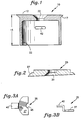
- the balance weight assembly comprises a one-piece hollow housing 10 that is closed on one end 12.
- the inventions will be described herein with a cylindrical shaped housing 10 (cylinder); however, any suitably shaped housing may be used with the present invention as will be understood by those skilled in the art.
- the height 15 of the cylinder is selected to span the distance from a rotor blade upper airfoil surface to a rotor blade lower airfoil surface.
- the closed end 12 of the cylinder is contoured to match the upper airfoil surface contour.
- a flared head 17 is formed at the closure end of the cylinder to mate with a countersink of an aperture formed in the rotor blade.
- a countersink aperture 20 is formed at the center of the cylinder closure end for receiving a balance weight retention stud which will be described in greater detail with respect to Fig. 5.
- the cylinder may be machined from a high strength, lightweight metal, such as aluminum or preferably titanium, or in some applications may be molded of a high strength, lightweight composite material to the required shape.
- the closure end flared head and bolt countersink may be machined, forged or molded as required.
- the open end 22 of the cylinder is closed by a cover plate 25 which is shown in Fig. 2.
- the cover plate is shaped to fit into the end of the cylinder and bear against the edge of the cylinder, and also has a flared head 27, that fits into a mating countersink formed in the rotor blade airfoil lower surface.
- a countersink aperture 30 is formed in the center of the cover plate cylinder for receiving a recessed locking nut, which will be described in greater detail with respect to Fig. 5.
- each of the retention clips 35 comprises a balance weight portion 37 and a retention tab 40.
- the design of the clips allows insertion through the interior diameter bore of the cylinder.
- a pair of opposing apertures 42 (Figs. 1 and 4) are formed in the cylinder 10 to receive the retention tabs 40.
- Cutouts 45 are formed in the balance weight portion of the retention clips so that the stud may pass down the center axis of the cylinder when the clips are installed in the cylinder, as shown in Fig. 4.
- the rotor blade balance weight assembly of the present invention is shown installed on a helicopter rotor blade 50.
- An aperture is formed in the rotor blade extending from the upper airfoil surface 52 to the lower airfoil surface 53.
- the aperture extends through the various rotor blade layers including the skin 55 and the spar 57.
- the balance weight assembly is installed near the tip end of the rotor blade, and therefore the skin layer 55 is the skin of the rotor blade tip. Therefore, when the balance weight assembly is installed, it provides the further advantage of securely holding the skin layer 55 to the spar layer 57 of the rotor blade, as will be described in greater detail hereinafter.
- the aperture is sized to snugly receive the cylinder.
- the aperture openings on the airfoil upper and lower surfaces provide countersink surfaces 59 for the flare of the cylinder closure end 17 and the cover plate 27.
- Bonding material such as epoxy, is disposed between the cylinder and the airfoil surfaces which form the aperture to securely hold the cylinder within the aperture.
- the retention clips 35 are inserted through the open end of the cylinder such that the tabs 40 are received through the opposing apertures 42 in the cylinder.
- the retention stud 70 is inserted through the aperture 20 formed in the closed end of the cylinder.
- the retention stud has a flared head to mate with the aperture countersink 20.
- a plurality of washer-like balance weights 72 are received over the stud for providing the required spanwise and chordwise rotor blade balance.
- a locking nut 75 is then installed on the stud 70 to securely hold the balance weights 72 and retention clips 40 against the closure end of the cylinder.
- a known thread-locking material may be inserted between the locking nut threads and stud threads to securely hold the locking nut 75 in place.
- other mechanical locking means may be used to lock the nut 75 in place.
- the retention clips 40 securely hold the cylinder to the upper airfoil surface 52 to provide additional retention of the balance weight assembly.
- Adhesive material such as epoxy, may be disposed between the interior surfaces of the upper airfoil and the retention tabs 40 to securely hold the tabs in place.
- the cover plate 25 is installed over the open end of the cylinder 10.
- a locking nut 78 having a tapered head is inserted through the cover plate countersink aperture and secured to the stud 70.
- Known thread-locking material may be disposed between the locking nut threads and stud threads, or other mechanical locking devices may be used to securely fasten the locking nut 78 to the stud 70.
- adhesive material such as epoxy
- adhesive material, such as epoxy may be disposed above the stud head and locking nut head to provide a smooth airfoil surface.
- the cylinder Prior to assembly of the balance weight assembly of the present invention, access is provided to the interior portions of the rotor blade through the aperture. Once installed, the cylinder adds to the structural integrity of the rotor blade, and the flare of the cylinder closure end 17 and the cover plate 27 provide for retention of blade components. For example, when the balance weight assembly is installed near the tip end of the blade, is provides for additional retention of the rotor blade tip to the spar.
- the invention was described using a cylindrically shaped housing 10; however, any suitably shaped housing may be used with the present invention. It will be further understood by those skilled in the art that the shape of the housing may be selected to provide desired size and strength characteristics.
- balance weight assembly is described herein as being installed using adhesive material, such a epoxy, the invention will work equally as well with the cylinder fastened to the upper airfoil surface by the retention clips 45, and the cover plate securely held in place by the locking nut 78. As will be understood by those skilled in the art, any suitable means of securely locking the locking nuts 75,78 in place may be used without departing from the scope of the present invention.
Landscapes
- Engineering & Computer Science (AREA)
- Mechanical Engineering (AREA)
- Aviation & Aerospace Engineering (AREA)
- Turbine Rotor Nozzle Sealing (AREA)
- Structures Of Non-Positive Displacement Pumps (AREA)
- Molds, Cores, And Manufacturing Methods Thereof (AREA)
Claims (6)
- Rotorblatt-Ausgleichsgewichtsanordnung zur Montage in einer in einem Rotorblatt (50) ausgebildeten Öffnung, wobei sich die Öffnung durch die gesamte Dicke des Rotorblatts von einer oberen Blattströmungsoberfläche (52) zu einer unteren Blattströmungsoberfläche (53) erstreckt, wobei die Anordnung folgendes aufweist:ein Gewichts-Festhaltegehäuse (10) mit einem hohlen Kern, einem geschlossenen Ende (12) und einem gegenüberliegenden offenen Ende (22), wobei der Außendurchmesser des Gehäuses eine derartige Kontur aufweist, daß er anliegend in die Rotorblattöffnung paßt;einen Schraubbolzen (70), der in dem Gehäusekern zentral angeordnet ist, wobei ein Ende des Schraubbolzens an dem geschlossenen Ende des Gehäuses befestigt ist;wenigstens ein Ausgleichsgewicht (72) mit einem dem Gehäusekern angepaßten Außendurchmesser, wobei jedes Ausgleichsgewicht eine zentrale Öffnung besitzt, durch die sich der Schraubbolzen hindurcherstreckt;eine erste Befestigungseinrichtung (75), die an dem anderen Ende des Schraubbolzens aufgenommen ist, um die Ausgleichsgewichte in dem Gehäusekern zu halten;eine Abdeckplatte (25), die dem offenen Ende des Gehäuses entsprechend ausgebildet ist und eine zentrale Öffnung (30) aufweist;eine zweite Befestigungseinrichtung (78), die durch die Abdeckplatten-Öffnung hindurch aufgenommen ist und an dem anderen Ende des Schraubbolzens aufgenommen ist, um die Abdeckplatte über dem offenen Ende des Gehäuses zu halten;gekennzeichnet durch:ein Paar Schlitze (42), die auf einander diametral gegenüberliegenden Seiten des Gehäuses ausgebildet sind; und durchein Paar Klammern (35), deren jede eine sich durch einen der Schlitze hindurcherstreckende Zungenfläche (40) sowie einen Ausgleichsgewichtsbereich (37) mit einem Ausschnitt (45) aufweist, durch den sich der Schraubbolzen (70) erstreckt, wobei die Klammern in dem Gehäusekern durch die erste Befestigungseinrichtung (75) festgehalten sind und sich die Zungen über den Außendurchmesser des Gehäuses hinaus in einen zentralen Hohlraum des Rotorblatts erstrecken.
- Rotorblatt-Ausgleichsgewichtsanordnung nach Anspruch 1, weiterhin mit:einer angesenkten Fläche (59), die an der oberen und der unteren Blattströmungsoberfläche um den Außendurchmesser der Öffnung herum ausgebildet ist;eine sich erweiternde Fläche (17), die an dem geschlossenen Ende des Gehäuses für einen paareingriff mit einer der angesenkten Blattströmungsoberflächen ausgebildet ist;eine sich erweiternde Fläche (27), die an der Abdeckplatte für einen Paareingriff mit der anderen angesenkten Blattströmungsoberfläche ausgebildet ist;wobei das geschlossene Ende (12) des Gehäuses und die Abdeckplatte (25) eine sichere Befestigung der Ausgleichsgewichtsanordnung an dem Rotorblatt schaffen, wenn die zweite Befestigungseinrichtung (78) durch die Abdeckplattenöffnung (30) hindurch aufgenommen ist und an dem anderen Ende des Schraubbolzens angebracht ist.
- Rotorblatt-Ausgleichsgewichtsanordnung nach Anspruch 1, wobei das geschlossene Ende (12) des Gehäuses und die Abdeckplatte (25) der Strömungskontur des Rotorblatts entsprechend ausgebildet sind.
- Rotorblatt-Ausgleichsgewichtsanordnung nach Anspruch 1, ferner mit Mitteln zum Kleben, die zwischen dem Gehäuse und dem Rotorblatt sowie zwischen der Abdeckplatte und dem Gehäuse und dem Rotorblatt zum sicheren Befestigen der Anordnung an dem Rotorblatt angeordnet sind.
- Rotorblatt-Ausgleichsgewichtsanordnung zur Anbringung in einer in einem Rotorblatt (50) ausgebildeten Öffnung, wobei sich die Öffnung durch die gesamte Dicke des Rotorblatts von einer oberen Blattströmungsoberfläche (52) zu einer unteren Blattströmungsoberfläche (53) erstreckt, wobei eine angesenkte Fläche (59) an der oberen und der unteren Blattströmungsoberfläche um den Außendurchmesser der Öffnung herum ausgebildet ist, wobei die Anordnung folgendes aufweist:ein Gewichts-Festhaltegehäuse (10) mit einem hohlen Kern, einem geschlossenen Ende (12) und einem gegenüberliegenden offenen Ende (22), wobei der Außendurchmesser des Gehäuses eine derartige Kontur besitzt, daß er anliegend in die Rotorblattöffnung paßt;wobei das geschlossene Ende (12) des Gehäuses einen Teil der Rotorblatt-Außenhaut bildet und der oberen Strömungskontur entsprechend ausgebildet ist, wobei das geschlossene Ende des Gehäuses eine sich erweiternde Fläche (17) für einen Paareingriff mit der angesenkten oberen Blattströmungsoberfläche (59) aufweist;einen in dem Gehäusekern zentral angeordneten Schraubbolzen (70), wobei das eine Ende des Schraubbolzens an dem geschlossenen Ende (12) des Gehäuses befestigt ist;wenigstens ein Ausgleichsgewicht (72) mit einem Außendurchmesser, der dem Gehäusekern entsprechend ausgebildet ist, wobei jedes Ausgleichsgewicht eine zentrale Öffnung besitzt, durch die sich der Schraubbolzen hindurcherstreckt;eine Klemmutter (75), die auf das andere Ende des Schraubbolzens aufgeschraubt ist, um die Ausgleichsgewichte in dem Gehäusekern festzuhalten;eine Abdeckplatte (25), die dem offenen Ende des Gehäuses entsprechend ausgebildet ist und eine zentrale angesenkte Öffnung (30) aufweist;wobei die Abdeckplatte (25) einen Teil der Rotorblatt-Außenhaut bildet und der unteren Strömungskontur entsprechend ausgebildet ist, wobei die Abdeckplatte eine sich erweiternde Fläche (27) für einen Paareingriff mit der angesenkten unteren Blattströmungsoberfläche (59) aufweist;eine sich durch die Abdeckplattenöffnung (30) hindurcherstreckende und auf das andere Ende des Schraubbolzens aufgeschraubte Schraube (78) zum Halten der Abdeckplatte über dem offenen Ende des Gehäuses, wobei die Schraube einen sich erweiternden Kopf für einen Paareingriff mit der angesenkten zentralen Öffnung der Abdeckplatte aufweist;gekennzeichnet durch:ein Paar Schlitze (42), die auf einander diametral gegenüberliegenden Seiten des Gehäuses ausgebildet sind; und durchein Paar Klammern (35), deren jede eine sich durch einen der Schlitze hindurcherstreckende Zungenfläche (40) sowie einen Ausgleichsgewichtsbereich (37) mit einem Ausschnitt (45) aufweist, durch den sich der Schraubbolzen (70) erstreckt, wobei die Klammern in dem Gehäusekern durch die Klemmutter (75) festgehalten sind und sich die Zungen über den Außendurchmesser des Gehäuses hinaus in einen zentralen Hohlraum des Rotorblatts erstrecken.
- Rotorblatt-Ausgleichsgewichtsanordnung nach Anspruch 5, ferner mit Mitteln zum Kleben, die zwischen dem Gehäuse und dem Rotorblatt sowie zwischen der Abdeckplatte und dem Gehäuse und dem Rotorblatt zum sicheren Anbringen der Anordnung an dem Rotorblatt angeordnet sind.
Applications Claiming Priority (3)
| Application Number | Priority Date | Filing Date | Title |
|---|---|---|---|
| US984027 | 1992-12-01 | ||
| US07/984,027 US5273398A (en) | 1992-12-01 | 1992-12-01 | Rotor blade balance weight assembly |
| PCT/US1993/011483 WO1994013530A2 (en) | 1992-12-01 | 1993-11-24 | Rotor blade balance weight assembly |
Publications (2)
| Publication Number | Publication Date |
|---|---|
| EP0670796A1 EP0670796A1 (de) | 1995-09-13 |
| EP0670796B1 true EP0670796B1 (de) | 1996-08-28 |
Family
ID=25530249
Family Applications (1)
| Application Number | Title | Priority Date | Filing Date |
|---|---|---|---|
| EP94902419A Expired - Lifetime EP0670796B1 (de) | 1992-12-01 | 1993-11-24 | Auswuchtgewichteinrichtung eines rotorblattes |
Country Status (7)
| Country | Link |
|---|---|
| US (1) | US5273398A (de) |
| EP (1) | EP0670796B1 (de) |
| JP (1) | JPH09505535A (de) |
| KR (1) | KR100311558B1 (de) |
| CA (1) | CA2146760A1 (de) |
| DE (1) | DE69304341T2 (de) |
| WO (1) | WO1994013530A2 (de) |
Families Citing this family (27)
| Publication number | Priority date | Publication date | Assignee | Title |
|---|---|---|---|---|
| US5475622A (en) * | 1994-08-31 | 1995-12-12 | United Technologies Corp. | Method and apparatus for balancing helicopter rotor blades |
| US5498137A (en) * | 1995-02-17 | 1996-03-12 | United Technologies Corporation | Turbine engine rotor blade vibration damping device |
| US5947686A (en) * | 1998-03-12 | 1999-09-07 | Keyes; Tina M. | Fan blade covers |
| US6139271A (en) * | 1998-03-17 | 2000-10-31 | Chadwick-Helmuth Company, Inc. | Helicopter rotor blade weighting |
| FR2776264B1 (fr) * | 1998-03-23 | 2000-06-02 | Eurocopter France | Pale a pas variable en materiau composite pour rotor d'helicoptere et procede de fabrication d'une telle pale |
| FR2784351B1 (fr) * | 1998-10-12 | 2000-12-08 | Eurocopter France | Dispositif et procede pour reduire les vibrations engendrees sur la structure d'un aeronef a voilure tournante, notamment un helicoptere |
| RU2175931C1 (ru) * | 2000-05-31 | 2001-11-20 | Шацкий Геннадий Юрьевич | Лопасть винта вертолета |
| EP1412245B1 (de) * | 2001-08-02 | 2011-03-02 | Bell Helicopter Textron Inc. | Ausgleichsgewichthalteanordnung für hubschrauberhauptrotorblatt |
| US7097427B2 (en) * | 2002-08-02 | 2006-08-29 | Bell Helicopter Textron Inc. | Helicopter main rotor blade balance weight retention assembly |
| US7465146B2 (en) * | 2005-12-05 | 2008-12-16 | General Electric Company | Methods and systems for turbine rotor balancing |
| US8029240B2 (en) * | 2007-11-08 | 2011-10-04 | The Boeing Company | Rotor blade adjustable weight retention system |
| US8192162B2 (en) | 2008-07-29 | 2012-06-05 | Loftus Robert T | Field installable and removable helicopter rotor blade vibration and blade tracking device |
| US8541916B2 (en) * | 2009-12-17 | 2013-09-24 | Siemens Energy, Inc. | Nut securing arrangement for electrical generator |
| US9440737B1 (en) | 2012-05-11 | 2016-09-13 | The Boeing Company | Apparatus to adjust airfoils of rotor blades |
| US9403594B2 (en) * | 2012-09-25 | 2016-08-02 | The Boeing Company | Adjustable payload enclosure for wing |
| US9249851B2 (en) * | 2012-11-14 | 2016-02-02 | The Boeing Company | Apparatus and method for tuning a vibratory response of a rotor blade |
| US9988146B2 (en) | 2013-11-08 | 2018-06-05 | Sikorsky Aircraft Corporation | Rotor balancing apparatus |
| US9914533B2 (en) * | 2013-12-05 | 2018-03-13 | Sikorsky Aircraft Corporation | In-wing device retention |
| DE102015218428A1 (de) * | 2014-10-03 | 2016-04-07 | Borgwarner Inc., Patent Department | Vorrichtungen und verfahren zur einstellung des gleichgewichts der rotationsanordnung eines turboladers |
| US10723448B2 (en) * | 2016-11-14 | 2020-07-28 | Textron Innovations Inc. | Rotor blade weight system |
| US10661487B2 (en) | 2016-11-30 | 2020-05-26 | The Boeing Company | Particulate-binder composite article and associated system and method for manufacturing the same |
| US11299263B2 (en) | 2016-12-07 | 2022-04-12 | Textron Innovations Inc. | Automatic, active blade tracking and balance system |
| US10981647B2 (en) * | 2017-08-02 | 2021-04-20 | Bell Helicopter Textron Inc. | Rotor span-balance pocket |
| US11254424B2 (en) * | 2019-09-30 | 2022-02-22 | Textron Innovations Inc. | Balance weight assemblies for rotor blades |
| US11220913B2 (en) * | 2019-10-23 | 2022-01-11 | Rolls-Royce Corporation | Gas turbine engine blades with airfoil plugs for selected tuning |
| CN113562163B (zh) * | 2021-08-26 | 2025-06-06 | 惠阳航空螺旋桨有限责任公司 | 一种螺旋桨桨叶配重挡圈及其配重结构 |
| US12491986B2 (en) * | 2023-12-19 | 2025-12-09 | Textron Innovations Inc. | Inertial weight system for main rotor blades |
Family Cites Families (8)
| Publication number | Priority date | Publication date | Assignee | Title |
|---|---|---|---|---|
| GB552745A (en) * | 1941-10-17 | 1943-04-22 | Albert Oliver Daniels | Improvements in, or relating to the balancing of blades of airscrews and the like |
| US2435604A (en) * | 1944-02-19 | 1948-02-10 | Bell Telephone Labor Inc | Propeller |
| US2494756A (en) * | 1945-03-26 | 1950-01-17 | Smith Corp A O | Balance assembly for propeller blades |
| DE2528007C2 (de) * | 1975-06-24 | 1984-04-19 | Messerschmitt-Bölkow-Blohm GmbH, 8000 München | Verfahren zur Korrektur der Schwerpunktlage und des Gewichts von Rotorblättern |
| US3999888A (en) * | 1975-06-25 | 1976-12-28 | United Technologies Corporation | Composite tip weight attachment |
| US4150920A (en) * | 1977-12-02 | 1979-04-24 | The United States Of America As Represented By The Secretary Of The Army | Rotor blade tipweight assembly |
| JPS61181794A (ja) * | 1985-02-06 | 1986-08-14 | Nippon Kokan Kk <Nkk> | 舶用プロペラ |
| DE4005896A1 (de) * | 1990-02-24 | 1991-08-29 | Messerschmitt Boelkow Blohm | Einrichtung zur auswuchtung eines rotorblattes |
-
1992
- 1992-12-01 US US07/984,027 patent/US5273398A/en not_active Expired - Lifetime
-
1993
- 1993-11-24 CA CA002146760A patent/CA2146760A1/en not_active Abandoned
- 1993-11-24 JP JP6514207A patent/JPH09505535A/ja active Pending
- 1993-11-24 WO PCT/US1993/011483 patent/WO1994013530A2/en not_active Ceased
- 1993-11-24 KR KR1019950702209A patent/KR100311558B1/ko not_active Expired - Fee Related
- 1993-11-24 DE DE69304341T patent/DE69304341T2/de not_active Expired - Lifetime
- 1993-11-24 EP EP94902419A patent/EP0670796B1/de not_active Expired - Lifetime
Also Published As
| Publication number | Publication date |
|---|---|
| WO1994013530A3 (en) | 1996-10-17 |
| KR100311558B1 (ko) | 2002-11-22 |
| KR950704150A (ko) | 1995-11-17 |
| DE69304341T2 (de) | 1997-04-17 |
| WO1994013530A2 (en) | 1994-06-23 |
| DE69304341D1 (de) | 1996-10-02 |
| EP0670796A1 (de) | 1995-09-13 |
| CA2146760A1 (en) | 1994-06-23 |
| JPH09505535A (ja) | 1997-06-03 |
| US5273398A (en) | 1993-12-28 |
Similar Documents
| Publication | Publication Date | Title |
|---|---|---|
| US5273398A (en) | Rotor blade balance weight assembly | |
| US3999888A (en) | Composite tip weight attachment | |
| US4150920A (en) | Rotor blade tipweight assembly | |
| US3504723A (en) | Floating nut insert | |
| US12077290B2 (en) | Assembly with captive nut | |
| US20040222329A1 (en) | Helicopter main rotor blade balance weight retention assembly | |
| EP1950414B1 (de) | Trennbares Rotorblatt einer Windkraftanlage | |
| EP2711293B1 (de) | Gehäuse mit einstellbarer Nutzlast für Flügel | |
| US5391028A (en) | Method for reducing radar cross-section of aircraft fasteners, and fastener assemblies for use therein | |
| US6889939B2 (en) | Device for fixing a member to an aircraft structure | |
| US20220001973A1 (en) | Fastening system for aircraft structures | |
| EP0432164A1 (de) | Verbesserungen an der spulkopfbefestigung. | |
| US5749670A (en) | Method for fastening parts together and resulting structure | |
| US5924650A (en) | Method and system for fastening aircraft assemblies | |
| EP3437991B1 (de) | Rotorlängenauswuchttasche | |
| GB2180905A (en) | Attaching fasteners to composite laminated members | |
| US2951541A (en) | Root retention structure for molded rotor blades | |
| EP3753852B1 (de) | Gegengewicht mit einstellbarem moment mit mehreren verriegelungsverfahren | |
| EP1412245B1 (de) | Ausgleichsgewichthalteanordnung für hubschrauberhauptrotorblatt | |
| US11472573B2 (en) | Tool for holding the side panels of a primary structure of an aircraft pylon during assembly thereof, and method for assembling a primary structure of an aircraft pylon using said holding tool | |
| RU2148532C1 (ru) | Лопасть несущего винта вертолета | |
| SU1364399A1 (ru) | Режущий инструмент | |
| HAYS et al. | Integrated technology wing design study[Final Report, Nov. 1979- Dec. 1980] | |
| Head et al. | Design of the McDonnell Douglas Helicopter Company- Advanced composite rotor system | |
| JPS5913150A (ja) | ロツドウエイト取付型の慣性力バランサ装置 |
Legal Events
| Date | Code | Title | Description |
|---|---|---|---|
| PUAI | Public reference made under article 153(3) epc to a published international application that has entered the european phase |
Free format text: ORIGINAL CODE: 0009012 |
|
| 17P | Request for examination filed |
Effective date: 19950531 |
|
| AK | Designated contracting states |
Kind code of ref document: A1 Designated state(s): DE FR GB IT NL |
|
| 17Q | First examination report despatched |
Effective date: 19951006 |
|
| GRAH | Despatch of communication of intention to grant a patent |
Free format text: ORIGINAL CODE: EPIDOS IGRA |
|
| GRAH | Despatch of communication of intention to grant a patent |
Free format text: ORIGINAL CODE: EPIDOS IGRA |
|
| GRAA | (expected) grant |
Free format text: ORIGINAL CODE: 0009210 |
|
| AK | Designated contracting states |
Kind code of ref document: B1 Designated state(s): DE FR GB IT NL |
|
| PG25 | Lapsed in a contracting state [announced via postgrant information from national office to epo] |
Ref country code: NL Free format text: LAPSE BECAUSE OF FAILURE TO SUBMIT A TRANSLATION OF THE DESCRIPTION OR TO PAY THE FEE WITHIN THE PRESCRIBED TIME-LIMIT Effective date: 19960828 |
|
| ET | Fr: translation filed | ||
| REF | Corresponds to: |
Ref document number: 69304341 Country of ref document: DE Date of ref document: 19961002 |
|
| ITF | It: translation for a ep patent filed | ||
| NLV1 | Nl: lapsed or annulled due to failure to fulfill the requirements of art. 29p and 29m of the patents act | ||
| PLBE | No opposition filed within time limit |
Free format text: ORIGINAL CODE: 0009261 |
|
| STAA | Information on the status of an ep patent application or granted ep patent |
Free format text: STATUS: NO OPPOSITION FILED WITHIN TIME LIMIT |
|
| 26N | No opposition filed | ||
| REG | Reference to a national code |
Ref country code: GB Ref legal event code: IF02 |
|
| PGFP | Annual fee paid to national office [announced via postgrant information from national office to epo] |
Ref country code: DE Payment date: 20091130 Year of fee payment: 17 |
|
| PGFP | Annual fee paid to national office [announced via postgrant information from national office to epo] |
Ref country code: IT Payment date: 20091119 Year of fee payment: 17 Ref country code: GB Payment date: 20091007 Year of fee payment: 17 Ref country code: FR Payment date: 20091120 Year of fee payment: 17 |
|
| GBPC | Gb: european patent ceased through non-payment of renewal fee |
Effective date: 20101124 |
|
| REG | Reference to a national code |
Ref country code: FR Ref legal event code: ST Effective date: 20110801 |
|
| REG | Reference to a national code |
Ref country code: DE Ref legal event code: R119 Ref document number: 69304341 Country of ref document: DE Effective date: 20110601 Ref country code: DE Ref legal event code: R119 Ref document number: 69304341 Country of ref document: DE Effective date: 20110531 |
|
| PG25 | Lapsed in a contracting state [announced via postgrant information from national office to epo] |
Ref country code: DE Free format text: LAPSE BECAUSE OF NON-PAYMENT OF DUE FEES Effective date: 20110531 |
|
| PG25 | Lapsed in a contracting state [announced via postgrant information from national office to epo] |
Ref country code: FR Free format text: LAPSE BECAUSE OF NON-PAYMENT OF DUE FEES Effective date: 20101130 |
|
| PG25 | Lapsed in a contracting state [announced via postgrant information from national office to epo] |
Ref country code: GB Free format text: LAPSE BECAUSE OF NON-PAYMENT OF DUE FEES Effective date: 20101124 |
|
| PG25 | Lapsed in a contracting state [announced via postgrant information from national office to epo] |
Ref country code: IT Free format text: LAPSE BECAUSE OF NON-PAYMENT OF DUE FEES Effective date: 20101124 |