EP0670585A2 - Power circuit breaker - Google Patents
Power circuit breaker Download PDFInfo
- Publication number
- EP0670585A2 EP0670585A2 EP95710005A EP95710005A EP0670585A2 EP 0670585 A2 EP0670585 A2 EP 0670585A2 EP 95710005 A EP95710005 A EP 95710005A EP 95710005 A EP95710005 A EP 95710005A EP 0670585 A2 EP0670585 A2 EP 0670585A2
- Authority
- EP
- European Patent Office
- Prior art keywords
- circuit breaker
- coil
- breaker according
- contact
- plunger
- Prior art date
- Legal status (The legal status is an assumption and is not a legal conclusion. Google has not performed a legal analysis and makes no representation as to the accuracy of the status listed.)
- Withdrawn
Links
Images


Classifications
-
- H—ELECTRICITY
- H01—ELECTRIC ELEMENTS
- H01H—ELECTRIC SWITCHES; RELAYS; SELECTORS; EMERGENCY PROTECTIVE DEVICES
- H01H71/00—Details of the protective switches or relays covered by groups H01H73/00 - H01H83/00
- H01H71/10—Operating or release mechanisms
- H01H71/1045—Multiple circuits-breaker, e.g. for the purpose of dividing current or potential drop
-
- H—ELECTRICITY
- H01—ELECTRIC ELEMENTS
- H01H—ELECTRIC SWITCHES; RELAYS; SELECTORS; EMERGENCY PROTECTIVE DEVICES
- H01H71/00—Details of the protective switches or relays covered by groups H01H73/00 - H01H83/00
- H01H71/10—Operating or release mechanisms
- H01H71/12—Automatic release mechanisms with or without manual release
- H01H71/40—Combined electrothermal and electromagnetic mechanisms
- H01H2071/407—Combined electrothermal and electromagnetic mechanisms the thermal element being heated by the coil of the electromagnetic mechanism
-
- H—ELECTRICITY
- H01—ELECTRIC ELEMENTS
- H01H—ELECTRIC SWITCHES; RELAYS; SELECTORS; EMERGENCY PROTECTIVE DEVICES
- H01H37/00—Thermally-actuated switches
- H01H37/02—Details
- H01H37/32—Thermally-sensitive members
- H01H37/52—Thermally-sensitive members actuated due to deflection of bimetallic element
- H01H37/54—Thermally-sensitive members actuated due to deflection of bimetallic element wherein the bimetallic element is inherently snap acting
-
- H—ELECTRICITY
- H01—ELECTRIC ELEMENTS
- H01H—ELECTRIC SWITCHES; RELAYS; SELECTORS; EMERGENCY PROTECTIVE DEVICES
- H01H71/00—Details of the protective switches or relays covered by groups H01H73/00 - H01H83/00
- H01H71/08—Terminals; Connections
Definitions
- the invention relates to a circuit breaker according to the preamble of claim 1.
- a circuit breaker with a magnetic tripping device which is designed up to about 50 A, is known from EP 144 799 B1. Such a circuit breaker should be miniaturized as much as possible despite increased performance.
- Miniature circuit breakers are provided according to the standard up to a rated current of 125 A. Since standard distances or standard pitches (e.g. 18 mm) are specified for the use of miniature circuit breakers and the switchgear with higher rated currents must also be used in the busbar system, the geometric dimensions and connection dimensions must also be congruent with the known miniature circuit breakers with smaller rated currents, even with miniature circuit breakers with higher rated currents be carried out. For economic reasons, it would be incorrect for miniature circuit breakers with high rated currents, to develop their own implementations, since the range of applications of such miniature circuit breakers is naturally smaller than with miniature circuit breakers with lower rated currents, especially since new tools and other production facilities would be required.
- standard distances or standard pitches e.g. 18 mm
- the invention has for its object to provide a circuit breaker for higher rated currents, the simple structure, as far as possible is miniaturized and can be manufactured while avoiding special designs.
- the invention provides a circuit breaker which, according to a preferred embodiment, has a magnetic release device which consists of two magnetic releases connected in parallel, i.e. the coils of the magnetic releases are connected in parallel with one another.
- the parallel connection of the coils of the magnetic release device in contrast to two mutually parallel circuit breakers, which are each designed up to 50 A and which would theoretically result in a 100 amp device, ensures a symmetrical current distribution.
- the simple parallel connection of two line circuit breakers does not provide a symmetrical current distribution between the two line circuit breakers connected in parallel, the parallel connection of which would take place with regard to the connection terminals.
- the two coils of the magnetic release device are connected in parallel in that an internal connection is provided.
- This additional internal connection or compensating line ensures that the current through the two coils is distributed evenly and that there is no different current flow through the two branches of the parallel connection due to different contact resistances at the contacts, at welding and connection points, etc.
- clamp clamps are preferably provided as connection terminals, which allow the connection of multi-wire conductors up to 50 mm2 by means of two screws in each case. If the standard pitch of, for example, 18 mm is maintained for the distance between the two clamping screws, it is easily possible to use such a circuit breaker for high rated currents for standard busbars together with switching devices with lower rated currents in a network.
- the coil is preferably used both as a magnetic release and as a heater for the thermal release, as a result of which the bimetal itself is not flowed through by current.
- the miniature circuit breaker according to the invention is used for a rated current of> 63 A, for example 100 A and, according to a preferred embodiment, consists of two 50 A miniature circuit breakers, is accordingly subjected to two 50 A, so that the 100 A miniature circuit breaker according to the invention has the same behavior shows like a 50 A circuit breaker.
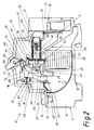
- a preferred embodiment of a circuit breaker 10 which has a narrowly constructed housing 11 made of an insulating plastic and on its rear side, in Fig. 1 and 2 below, suspension mounts 12 and 13 for a conventional mounting rail.
- the housing 11 has an interior 14 and an upper section 15 with a connecting terminal 16 and a lower section 17 with a connecting terminal 18th
- the connecting terminal 16 is connected to the movable contact 25 of the contact device 21 via a movable strand 24.
- the complementary fixed contact 26 of the contact device 21 is formed as a section of an approximately 1.2 mm thick solid conductor 27 which extends from the overcurrent release 22 via the fixed contact 26 and a horn section 28 to the high-performance arc extinguishing package 23.
- An arc-shaped arc guide plate 30 extends between an angled section 29 of the connecting terminal 16, to which the strand 24 is also fastened, and a rear region near the quenching package 23.
- connection terminal 18 is connected to the overcurrent release 22 via a welding contact point 31.
- the overcurrent release 22 has a heat-conducting, rotationally symmetrical hollow cylindrical support body 32 with a section which a coil 33 is wound in close contact.
- One end of the coil 33 is connected to the connecting terminal 18 via the soldering point 31.
- the other end of the coil 33 is guided to a soldering point 34 which is connected to the conductor 27 via a holding plate 35 in the front region of the support body 32.
- the holding plate 35 is used to fasten the support body 32 in the interior 14 of the housing 11 by means of an axis 36, which simultaneously functions as an axis of rotation for a two-armed lever 37.
- the two-armed lever 37 has a first arm 38 with a unlatching nose 39, a molded-in position section 40, which is overlapped by the holding plate 35, and a second arm 41, which is designed to strike a plunger 42 of the overcurrent release 22 within the position section 40.
- the second arm 41 has a molded-on baffle 43 on its rear side (in FIGS. 1 and 2 on its underside) and a lug 44 through which the movable contact 25 can be opened, which is located on a first arm 45 of a two-armed contact lever 46 is located.
- a movable plunger loading anchor 47 is arranged, which is biased by a spring 48, which is guided by the plunger 42, against a plunger guide core 49.
- the tappet guide core 49 has a central bore 50 in which the tappet 42 is guided.
- the tappet guide core 49 like the tappet actuating anchor 47, is constructed to be rotationally symmetrical.
- the plunger guide core 49 is fastened in the hollow cylindrical interior of the support body 32.
- a bimetallic chamber 51 is formed in front of the tappet guide core 49, ie to the left of this in FIGS. 1 and 2, in which a bimetallic snap disk 52 is held in an enlarged section of the supporting body 32 by means of a disk-shaped element 53.
- the bimetallic disc 52 has a central bore, which only slightly exceeds the diameter of the plunger 42, in order to be able to act on a disc engagement molding 54 of the plunger 42 for a thermally induced release or disengagement of the plunger 42.
- the disc element 53 also has a passage opening 55 for the plunger 42, which protrudes up to its stop on the two-armed lever 37 in its molded-in position section 40.
- the conductor 27 is fastened in a receptacle 56 of the disk-shaped element 53 and is conductively connected to the other end of the coil, the conductor 27 having a straight arc guide rail section 57 after the horn section 28, which extends parallel to the front side of the quenching package 23.
- the unlatching lug 39 of the two-armed lever 37 is provided for engagement on an angled release lever 58, which forms a functional component of the switching lock 19.
- the trigger lever 58 is mounted on an axle 59 fixed to the housing, which also forms the axis of rotation for the switching knob 20.
- the switching lock 19 also includes the two-armed contact lever 46 with an elongated hole 61, which extends approximately transversely to the contact lever 46 and through which a housing-fixed axis 63 engages to guide the contact lever 46.
- the contact lever 46 is biased in a clockwise direction on the housing 11 via a spring 67 and is connected in an articulated manner to an intermediate lever 69.
- the nose-shaped free end 73 of the intermediate lever 69 engages in a latching manner with a stop 70 of the release lever 58 and has an elongated hole 74.
- a bracket 75 engages with one end in the elongated hole 74 and with its other end in a bore 76 which is formed in a projection 77 of the switching knob 20 is formed.
- the plunger 42 is disengaged from the position shown in FIG. 1 either electromagnetically or by means of the bimetallic disk 52 due to its snapping and strikes the second Arm 41 of the two-armed lever 37. This causes the movable contact 25 of the contact device 21 to be opened by means of the nose 44, which strikes the first arm 45 of the contact lever 46.
- the material of the two-armed lever 37 which consists of an insulating material which emits gas under the action of an arc, gas is released intermittently, in particular from plexiglass. This advantageously presses the resulting arc to the quenching package 23, the baffle 43 of the lever 37 guiding the arc in the intended direction when it strikes.
- the unlatching lug 39 of the two-armed lever 37 engages the release lever 58, as a result of which the latch is released with the intermediate lever 69 and the contact lever 45 is rotated clockwise under the pressure of the spring 67.
- the bracket 75 is moved to the right via the intermediate lever 69 with the result that the switching knob 20 rotates counterclockwise into the switched-off position and the movable contact lever 46 is held in the open position.
- the switching mechanism 19 thus reliably keeps the contact device 21 open.
- circuit breaker for a rated current of, for example, 100 A, a double design of the individual parts described in connection with FIGS. 1 and 2 is provided, that is to say all the parts described above are provided twice and thus also two overcurrent releases 22 in the still to be described Are connected in parallel.
- the connection terminals 16 of the two units are additionally connected in parallel, as will be described below.
- the two coils 33 are connected to one another on the input side and also on the output side in order to ensure a symmetrical current distribution.
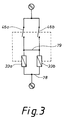
- the two coils are designated 33a, 33b, which are each assigned to the tripping mechanism or overcurrent release 22 described in connection with Figs. 1 and 2.
- the contact or contact lever assigned to each coil 33a, 33b is designated 46a or 46b in FIG. 3. 3
- the contact lever 46a is thus opened by the plunger 42 moved by means of the coil 33a and the contact lever 46b by the plunger 42 activated by the coil 33b. This means that the contact levers 46a, 46b are not coupled to one another via a mechanism or must be coupled. If an overcurrent flows through the coil 33a, the contact lever 46a is opened. If an overcurrent continues to flow, then the contact lever 46b is opened immediately within a very short time due to the current flow then occurring exclusively via the coil 33b.
- the two coils 33a, 33b are electrically coupled to one another on the output side by a connection 79, and the two coils are likewise coupled directly to one another by a corresponding electrical connection on the input side.
- FIG. 4 shows a view of the line circuit breaker according to the invention, in which the two toggles designated 20a, 20b in FIG. 4 are coupled to one another by a handle connection 80.
- a handle connection 80 In this way, both a manual closing of both contact levers 46a, 46b after tripping by an overcurrent is ensured, as well as the simultaneous opening of these contact levers in a manual manner.
- the connection of the input-side as well as the output-side conductors is carried out with the help of trestle clamps, which are shown schematically in FIG. 5 and are therefore provided on the input side as well as the output side of the line circuit breaker.
- 5 is preferably located on the side of the circuit breaker shown on the left and right in FIG. 4, with the clamp clamp representing the connection to the connection terminals designated 16 and 18 in FIGS. 1 and 2, respectively.
- the coil 33a, 33b is used both as a magnetic release and as a heater for the thermal release, as a result of which the bimetal used in the form of the bimetallic snap disk 52 does not have a current flowing through it.
- the circuit breaker according to the invention uses two identical units, with the proviso that the two coils of the two units are connected to one another on the input side and on the output side.
- a double-T housing for accommodating the line circuit breaker according to the invention and the larger connecting terminal in the form of the trestle clamp terminals according to FIG. 5, no further new parts are required for known rated circuit breakers for small rated currents.
Abstract
Description
Die Erfindung betrifft einen Leitungsschutzschalter nach dem Oberbegriff des Patentanspruchs 1.The invention relates to a circuit breaker according to the preamble of claim 1.
Ein Leitungsschutzschalter mit einer Magnetauslöseeinrichtung, der bis etwa 50 A konzipiert ist, ist aus der EP 144 799 B1 bekannt. Ein derartiger Leitungsschutzschalter soll trotz erhöhter Leistung soweit wie möglich miniaturisiert werden.A circuit breaker with a magnetic tripping device, which is designed up to about 50 A, is known from EP 144 799 B1. Such a circuit breaker should be miniaturized as much as possible despite increased performance.
Leitungsschutzschalter sind nach der Norm bis zu einem Bemessungsstrom von 125 A vorgesehen. Da für den Einsatz von Leitungsschutzschaltern Normabstände bzw. Normteilungen (z.B. 18 mm) vorgegeben sind und auch die Schaltgerät mit höheren Bemessungsströmen im Sammelschienenverbund eingesetzt werden müssen, müssen auch bei Leitungsschutzschaltern mit höheren Bemessungsströmen die geometrischen Abmessungen und Anschlußmaße kongruent zu den bekannten Leitungsschutzschaltern mit kleineren Bemessungsströmen ausgeführt werden. Aus wirtschaftlichen Erwägungen wäre es unrichtig, für Leitungsschutzschalter mit hohen Bemessungsströmen, eigene Realisierungen zu entwickeln, da die Anwendungsbreite derartiger Leitungsschutzschalter naturgemäß kleiner ist als bei Leitungsschutzschaltern mit niedrigeren Bemessungsströmen zumal neue Werkzeuge und andere Fertigungseinrichtungen erforderlich wären.Miniature circuit breakers are provided according to the standard up to a rated current of 125 A. Since standard distances or standard pitches (e.g. 18 mm) are specified for the use of miniature circuit breakers and the switchgear with higher rated currents must also be used in the busbar system, the geometric dimensions and connection dimensions must also be congruent with the known miniature circuit breakers with smaller rated currents, even with miniature circuit breakers with higher rated currents be carried out. For economic reasons, it would be incorrect for miniature circuit breakers with high rated currents, to develop their own implementations, since the range of applications of such miniature circuit breakers is naturally smaller than with miniature circuit breakers with lower rated currents, especially since new tools and other production facilities would be required.
Der Erfindung liegt die Aufgabe zugrunde, einen Leitungsschutzschalter für höhere Bemessungsströme zu schaffen, der einfachen Aufbau hat, soweit wie möglich miniaturisiert ist und unter Vermeidung von Sonderkonstruktionen herstellbar ist.The invention has for its object to provide a circuit breaker for higher rated currents, the simple structure, as far as possible is miniaturized and can be manufactured while avoiding special designs.
Diese Aufgabe wird erfindungsgemäß durch die im kennzeichnenden Teil des Patentanspruchs 1 angegebenen Merkmale gelöst.This object is achieved by the features specified in the characterizing part of patent claim 1.
Weitere Ausgestaltungen des Leitungsschutzschalters ergeben sich aus den Unteransprüchen.Further designs of the circuit breaker result from the subclaims.
Die Erfindung schafft einen Leitungsschutzschalter, der gemäß einer bevorzugten Ausführungsform eine Magnetauslöseeinrichtung aufweist, die aus zwei parallel geschalteten Magnetauslösern besteht, d.h., daß die Spulen der Magnetauslöser zueinander parallel geschaltet sind.The invention provides a circuit breaker which, according to a preferred embodiment, has a magnetic release device which consists of two magnetic releases connected in parallel, i.e. the coils of the magnetic releases are connected in parallel with one another.
Gemäß der Erfindung werden durch die Parallelschaltung der Spulen der Magnetauslöseeinrichtung im Gegensatz zu zwei zueinander parallel geschalteten Leitungsschutzschaltern, die jeweils bis zu 50 A ausgelegt sind und wodurch theoretisch ein 100 Ampère-Gerät entstünde, eine symmetrische Stromverteilung gewährleistet. Die einfache Parallelschaltung von zwei Leitungsschutzschaltern liefert im Vergleich zur erfindungsgemäßen Lösung keine symmetrische Stromverteilung zwischen den zwei parallel geschalteten Leitungsschutzschaltern, deren Parallelschaltung hinsichtlich der Anschlußklemmen erfolgen würde.According to the invention, the parallel connection of the coils of the magnetic release device in contrast to two mutually parallel circuit breakers, which are each designed up to 50 A and which would theoretically result in a 100 amp device, ensures a symmetrical current distribution. Compared to the solution according to the invention, the simple parallel connection of two line circuit breakers does not provide a symmetrical current distribution between the two line circuit breakers connected in parallel, the parallel connection of which would take place with regard to the connection terminals.
Gemäß der Erfindung werden zusätzlich zu der Parallelschaltung der beiden Anschlußklemmen die beiden Spulen der Magnetauslöseeinrichtung dadurch parallel geschaltet, daß eine innere Verbindung vorgesehen ist. Durch diese zusätzliche innere Verbindung bzw. Ausgleichsleitung ist sichergestellt, daß sich der Strom durch die beiden Spulen gleichmäßig aufteilt und nicht durch unterschiedliche Übergangswiderstände an den Kontakten, an Schweiß- und Verbindungsstellen usw. ein unterschiedlicher Stromfluß über die beiden Zweige der Parallelschaltung vorliegt.According to the invention, in addition to the parallel connection of the two terminals, the two coils of the magnetic release device are connected in parallel in that an internal connection is provided. This additional internal connection or compensating line ensures that the current through the two coils is distributed evenly and that there is no different current flow through the two branches of the parallel connection due to different contact resistances at the contacts, at welding and connection points, etc.
Gemäß der Erfindung werden als Anschlußklemmen vorzugsweise Bockschellenklemmen vorgesehen, die mittels jeweils zweier Schrauben den Anschluß von mehrdrahtigen Leitern bis 50 mm² gestatten. Wird für den Abstand der beiden Klemmschrauben das Normteilungsmaß von beispielsweise 18 mm eingehalten, ist es ohne weiteres möglich, einen derartigen Leitungsschutzschalter für hohe Bemessungsströme für handelsübliche Sammelschienen zusammen mit Schaltgeräten geringerer Bemessungsströme im Verbund einzusetzen.According to the invention, clamp clamps are preferably provided as connection terminals, which allow the connection of multi-wire conductors up to 50 mm² by means of two screws in each case. If the standard pitch of, for example, 18 mm is maintained for the distance between the two clamping screws, it is easily possible to use such a circuit breaker for high rated currents for standard busbars together with switching devices with lower rated currents in a network.
Bei dem erfindungsgemäßen Leitungsschutzschalter wird vorzugsweise die Spule sowohl als Magnetauslöser als auch als Heizung für den thermischen Auslöser verwendet, infolgedessen das Bimetall selbst nicht stromdurchflossen ist.In the line circuit breaker according to the invention, the coil is preferably used both as a magnetic release and as a heater for the thermal release, as a result of which the bimetal itself is not flowed through by current.
Der erfindungsgemäße Leitungsschutzschalter wird für einen Bemessungsstrom von >63 A zum Beispiel 100 A eingesetzt und besteht nach einer bevorzugten Ausführungsform aus zwei 50 A-Leitungsschutzschaltern, wird demnach mit zweimal 50 A beaufschlagt, so daß der 100 A-Leitungsschutzschalter gemäß der Erfindung das gleiche Verhalten zeigt wie ein 50 A-Leitungsschutzschalter.The miniature circuit breaker according to the invention is used for a rated current of> 63 A, for example 100 A and, according to a preferred embodiment, consists of two 50 A miniature circuit breakers, is accordingly subjected to two 50 A, so that the 100 A miniature circuit breaker according to the invention has the same behavior shows like a 50 A circuit breaker.
Nachfolgend wird der erfindungsgemäße Leitungsschutzschalter anhand von Zeichnungen zur Erläuterung weiterer Merkmale beschrieben. Es zeigen:
- Fig. 1 und 2
- eine Darstellung einer bevorzugten Ausführungsform eines Leitungsschutzschalters,
- Fig. 3
- das Schaltbild der Spulen für die Magnetauslöseeinrichtung gemäß der Erfindung, und
- Fig. 4
- eine Draufsicht auf einen Leitungsschutzschalter gemäß der Erfindung und
- Fig. 5
- eine Schnittansicht einer Bockschellenklemme
- 1 and 2
- an illustration of a preferred embodiment a circuit breaker,
- Fig. 3
- the circuit diagram of the coils for the magnetic release device according to the invention, and
- Fig. 4
- a plan view of a circuit breaker according to the invention and
- Fig. 5
- a sectional view of a trestle clamp
In Fig. 1 ist eine bevorzugte Ausbildungsform eines Leitungsschutzschalters 10 dargestellt, der ein in Schmalbauweise herstelltes Gehäuse 11 aus einem isolierenden Kunststoff aufweist und an seiner Hinterseite, in Fig. 1 und 2 unten, Einhängeaufnahmen 12 und 13 für eine übliche Montageschiene aufweist. Das Gehäuse 11 besitzt einen Innenraum 14 und einen oberen Abschnitt 15 mit einer Anschlußklemme 16 sowie einen unteren Abschnitt 17 mit einer Anschlußklemme 18.In Fig. 1, a preferred embodiment of a
In dem Innenraum 14 sind ein Schaltschloß 19 mit einem aus dem Gehäuse 11 ragenden beweglichen Schaltknebel 20 und einer Kontakteinrichtung 21, ein Überstromauslöser 22 und ein Hochleistungs-Lichtbogenlöschpaket 23 befestigt.In the
Die Anschlußklemme 16 steht über eine bewegliche Litze 24 mit dem bewegbaren Kontakt 25 der Kontakteinrichtung 21 in Verbindung. Der komplementäre feste Kontakt 26 der Kontakteinrichtung 21 ist als Abschnitt eines etwa 1,2 mm dicken massiven Leiters 27 ausgebildet, der sich von dem Überstromauslöser 22 über den festen Kontakt 26 und einem Hornabschnitt 28 zu dem Hochleistungs-Lichtbogenlöschpaket 23 erstreckt. Zwischen einem abgewinkeltem Abschnitt 29 der Anschlußklemme 16, an dem auch die Litze 24 befestigt ist, und einem nahe dem Löschpaket 23 liegenden hinteren Bereich erstreckt sich ein bogenförmiges Lichtbogenleitblech 30.The
Die Anschlußklemme 18 ist über eine Schweißkontaktstelle 31 mit dem Überstromauslöser 22 verbunden. Genauer gesagt, besitzt der Überstromauslöser 22 einen gut wärmeleitenden rotationssymmetrischen hohlzylindrischen Tragkörper 32 mit einem Abschnitt, auf dem eine Spule 33 in dichtem Kontakt aufgewickelt ist. Die Spule 33 steht mit ihrem einen Ende über die Lötstelle 31 mit der Anschlußklemme 18 in Verbindung. Das andere Ende der Spule 33 ist zu einer Lötstelle 34 geführt, die über ein Halteblech 35 im vorderen Bereich des Tragkörpers 32 mit dem Leiter 27 verbunden ist. Das Halteblech 35 dient zur Befestigung des Tragkörpers 32 in dem Innenraum 14 des Gehäuses 11 mittels einer Achse 36, die gleichzeitig als Drehachse für einen zweiarmigen Hebel 37 fungiert.The
Der zweiarmige Hebel 37 besitzt einen ersten Arm 38 mit einer Entklinkungsnase 39, einen eingeformten Lageabschnitt 40, der von dem Halteblech 35 übergriffen, wird und einen zweiten Arm 41, der für den Aufschlag eines Stößels 42 des Überstromauslösers 22 innerhalb des Lageabschnitts 40 ausgebildet ist. Außerdem weist der zweite Arm 41 eine an seiner Rückseite (in Fig. 1 und 2 an seiner Unterseite) eine angeformte Prallwand 43 sowie eine Nase 44 auf, durch die der bewegliche Kontakt 25 aufschlagbar ist, der sich an einem ersten Arm 45 eines zweiarmigen Kontakthebels 46 befindet.The two-
In dem Tragkörper 32 des Überstromauslösers 22 ist ein beweglicher Stößelbeaufschlagungsanker 47 angeordnet, der über eine Feder 48, die von dem Stößel 42 geführt wird, gegenüber einem Stößelführungskern 49 vorgespannt ist. Der Stößelführungskern 49 besitzt eine zentrische Bohrung 50, in der der Stößel 42 geführt ist. Der Stößelführungskern 49 ist ebenso wie der Stößelbetätigungsanker 47 rotationssymmetrisch aufgebaut. Im Gegensatz zu dem beweglichen Stößelbeaufschlagungsanker 47 ist der Stößelführungskern 49 im hohlen zylindrischen Innenraum des Tragkörpers 32 befestigt.In the
Vor dem Stößelführungskern 49, d. h. in Fig. 1 und 2 links von diesem, ist eine Bimetall-Kammer 51 gebildet, in der eine Bimetall-Schnappscheibe 52 mittels eines scheibenförmigen Elements 53 in einen erweiterten Abschnitt des Tragkörpers 32 gehaltert ist.A
Die Bimetall-Scheibe 52 besitzt eine zentrale Bohrung, die nur geringfügig den Durchmesser des Stößels 42 übersteigt, um eine Scheibenangriffsanformung 54 des Stößels 42 für eine thermisch hervorgerufene Auslösung bzw. ein Ausrücken des Stößels 42 beaufschlagen zu können. Das Scheibenelement 53 besitzt weiterhin eine Durchtrittsöffnung 55 für den Stößel 42, der bis nahe zu seinem Anschlag an dem zweiarmigen Hebel 37 in dessen eingeformten Lageabschnitt 40 vorsteht. Der Leiter 27 ist in einer Aufnahme 56 des scheibenförmigen Elements 53 befestigt und leitend mit dem anderen Spulenende verbunden, wobei der Leiter 27 nach dem Hornabschnitt 28 einen geraden Lichtbogenleitschienenabschnitt 57 aufweist, der sich parallel zu der vorderen Seite des Löschpaketes 23 erstreckt.The
Die Entklinkungsnase 39 des zweiarmigen Hebels 37 ist für den Eingriff an einem abgewinkelten Auslösehebel 58 vorgesehen, der einen funktionellen Bestandteil des Schaltschlosses 19 bildet. Der Auslösehebel 58 ist an einer gehäusefesten Achse 59 gelagert, die auch die Drehachse für den Schaltknebel 20 bildet.The
Zu dem Schaltschloß 19 gehört desweiteren der bereits erwähnte zweiarmige Kontakthebel 46 mit einem Langloch 61, das sich etwa quer zu dem Kontakthebel 46 erstreckt und durch das eine gehäusefeste Achse 63 zur Führung des Kontakthebels 46 greift. Der Kontakthebel 46 stützt sich über eine Feder 67 an dem Gehäuse 11 im Uhrzeigersinn vorgespannt ab und ist gelenkig mit einem Zwischenhebel 69 verbunden. Das nasenförmige freie Ende 73 des Zwischenhebels 69 greift verklinkend an einen Anschlag 70 des Auslösehebels 58 an und besitzt ein Langloch 74. Ein Bügel 75 greift mit einem Ende in das Langloch 74 und mit seinem anderen Ende in eine Bohrung 76, die in einer Anformung 77 des Schaltknebels 20 gebildet ist.The
Kommt es nun infolge eines höheren Überstroms zu einer auslösenden Erregung der Spule 33 oder aufgrund länger dauernden geringeren Überstroms durch die wärmeleitende Kontaktierung der auf den Tragkörper 32 gewickelten Spule 33 zu einer Erwärmung des Tragkörpers 32, die sich der Bimetall-Schnappscheibe mitteilt, wird der Stößel 42 aus der in Fig. 1 gezeigten Lage entweder elektromagnetisch oder mittels der Bimetall-Scheibe 52 aufgrund deren Umschnappung ausgerückt und schlägt auf den zweiten Arm 41 des zweiarmigen Hebels 37 auf. Hierdurch erfolgt ein Aufschlagen des bewegbaren Kontaktes 25 der Knontakteinrichtung 21 mittels der Nase 44, die auf den ersten Arm 45 des Kontakthebels 46 trifft. Dabei wird aufgrund der besonderen Wahl des Materials des zweiarmigen Hebels 37, der aus einem isolierenden Werkstoff besteht, welcher unter Lichtbogeneinwirkung Gas abgibt, insbesondere aus Plexiglas, Gas stoßweise freigesetzt. Dieses drückt vorteilhaft den entstehenden Lichtbogen zu dem Löschpaket 23, wobei die Prallwand 43 des Hebels 37 beim Aufschlagen den Lichtbogen in die vorgesehene Richtung leitet.Is there now a triggering excitation of the
Gleichzeitig greift die Entklinkungsnase 39 des zweiarmigen Hebels 37 an den Auslösehebel 58 an, wodurch die Verklinkung mit dem Zwischenhebel 69 gelöst und der Kontakthebel 45 unter dem Druck der Feder 67 im Uhrzeigersinn verdreht wird. Hierdurch wird über den Zwischenhebel 69 der Bügel 75 mit der Folge nach rechts bewegt, daß sich der Schaltknebel 20 entgegen dem Uhrzeigersinn in Ausschaltstellung verdreht und der bewegliche Kontakthebel 46 in geöffneter Stellung gehalten wird. Das Schaltschloß 19 hält somit die Kontakteinrichtung 21 zuverlässig offen.At the same time, the
Fig. 2 zeigt eine Stellung des Leitungsschutzschalters 10 nach elektromagnetischer oder thermoelektrischer Auslösung mit sicher geöffneter Kontakteinrichtung 21.2 shows a position of the
Gemäß einer bevorzugten Ausführungsform des erfindungsgemäßen Leitungsschutzschalters ist für einen Bemessungsstrom von zum Beispiel 100 A eine doppelte Ausbildung der in Verbindung mit Fig. 1 und 2 beschriebenen Einzelteile vorgesehen, das heißt, alle vorstehend beschriebenen Teile sind doppelt vorgesehen und somit auch zwei Überstromauslöser 22, die in der noch zu beschreibenden Weise parallel geschaltet sind. Die Anschlußklemmen 16 der beiden Einheiten sind zusätzlich parallel geschaltet, wie dies noch nachfolgend beschrieben ist.According to a preferred embodiment of the circuit breaker according to the invention, for a rated current of, for example, 100 A, a double design of the individual parts described in connection with FIGS. 1 and 2 is provided, that is to say all the parts described above are provided twice and thus also two
Zusätzlich sind gemäß der Erfindung die beiden Spulen 33 eingangsseitig wie auch ausgangsseitig miteinander verbunden, um eine symmetrische Stromverteilung zu gewährleisten.In addition, according to the invention, the two
In Fig. 3 sind die beiden Spulen mit 33a, 33b bezeichnet, die jeweils dem in Verbindung mit Fig. 1 und 2 beschriebenen Auslösemechanismus bzw. Überstromauslöser 22 zugeordnet sind. Der jeder Spule 33a, 33b zugeordnete Kontakt oder Kontakthebel ist in Fig. 3 mit 46a bzw. 46b bezeichnet. Nach Fig. 3 wird somit der Kontakthebel 46a durch den mittels der Spule 33a bewegten Stößel 42 geöffnet und der Kontakthebel 46b durch den von der Spule 33b aktivierten Stößel 42. Dies bedeutet, daß die Kontakthebel 46a, 46b nicht über eine Mechanik miteinander gekoppelt sind oder gekoppelt sein müssen. Fließt ein Überstrom durch die Spule 33a, wird der Kontakthebel 46a geöffnet. Fließt weiterhin ein Überstrom, dann wird innerhalb kürzester Zeit durch den dann erfolgenden Stromfluß ausschließlich über die Spule 33b auch sofort der Kontakthebel 46b geöffnet.In Fig. 3, the two coils are designated 33a, 33b, which are each assigned to the tripping mechanism or
Die beiden Spulen 33a, 33b sind ausgangsseitig durch eine Verbindung 79 elektrisch miteinander gekoppelt und eingangsseitig sind die beiden Spulen durch eine entsprechende elektrische Verbindung ebenfalls direkt miteinander gekoppelt.The two
Fig. 4 zeigt eine Ansicht des erfindungsgemäßen Leitungsschutzschalters, bei dem die beiden in Fig. 4 mit 20a, 20b bezeichneten Schaltknebel durch eine Griffverbindung 80 miteinander gekoppelt sind. Auf diese Weise wird sowohl ein manuelles Schließen beider Kontakthebel 46a, 46b nach erfolgter Auslösung durch einen Überstrom gewährleistet, wie auch das gleichzeitige Öffnen dieser Kontakthebel auf manuelle Weise.FIG. 4 shows a view of the line circuit breaker according to the invention, in which the two toggles designated 20a, 20b in FIG. 4 are coupled to one another by a
Gemäß einer bevorzugten Ausführungsform des erfindungsgemäßen Leitungsschutzschalters erfolgt der Anschluß der eingangsseitigen wie auch ausgangsseitigen Leiter mit Hilfe von Bockschellenklemmen, die in Fig. 5 schematisch dargestellt sind und somit eingangsseitig wie auch ausgangsseitig des Leitungsschutzschalters vorgesehen sind. Die Bockschellenklemme 81 gemäß Fig. 5 befindet sich vorzugsweise auf der in Fig. 4 links wie auch rechts dargestellten Seite des Leitungsschutzschalters, wobei die Bockschellenklemme jeweils den Anschluß zu den in Fig. 1 und 2 mit 16 bzw. 18 bezeichneten Anschlußklemmen darstellt.According to a preferred embodiment of the circuit breaker according to the invention, the connection of the input-side as well as the output-side conductors is carried out with the help of trestle clamps, which are shown schematically in FIG. 5 and are therefore provided on the input side as well as the output side of the line circuit breaker. 5 is preferably located on the side of the circuit breaker shown on the left and right in FIG. 4, with the clamp clamp representing the connection to the connection terminals designated 16 and 18 in FIGS. 1 and 2, respectively.
Bei dem erfindungsgemäßen Leitungsschutzschalter wird jeweils die Spule 33a, 33b als Magnetauslöser als auch als Heizung für den thermischen Auslöser verwendet, infolgedessen das eingesetzte Bimetall in Form der Bimetall-Schnappscheibe 52 nicht stromdurchflossen ist. Die zusätzliche Parallelschaltung der Spulen 33a, 33b, nämlich spuleneingangsseitig wie auch spulenausgangsseitig, wie dies in Fig. 3 dargestellt ist, bringt zusätzlich zu der Parallelschaltung der beiden Einheiten mittels der Bockschellenklemmen 81 nach Fig. 5 eine symmetrische Stromverteilung und vermeidet Schwierigkeiten in Folge unterschiedlicher, fertigungsbedingter Innenwiderstände.In the circuit breaker according to the invention, the
Im Prinzip verwendet der erfindungsgemäße Leitungsschutzschalter den Einsatz von zwei identischen Einheiten mit der Maßgabe, daß die beiden Spulen der beiden Einheiten jeweils eingangsseitig als auch ausgangsseitig miteinander verbunden sind. Neben einem Doppel-T-Gehäuse zur Aufnahme des erfindungsgemäßen Leitungsschutzschalters und der größeren Anschlußklemme in Form der Bockschellenklemmen nach Fig. 5 sind gegenüber bekannten derartigen Leitungsschutzschaltern für kleine Bemessungsströme keine weiteren Neuteile erforderlich.In principle, the circuit breaker according to the invention uses two identical units, with the proviso that the two coils of the two units are connected to one another on the input side and on the output side. In addition to a double-T housing for accommodating the line circuit breaker according to the invention and the larger connecting terminal in the form of the trestle clamp terminals according to FIG. 5, no further new parts are required for known rated circuit breakers for small rated currents.
Gleichwohl vorliegende Erfindung in Verbindung mit einer bevorzugten Ausführungsform eines Leitungsschutzschalters entsprechend Fig. 1 und 2 beschrieben ist, läßt sich das Prinzip auch bei anderen Leitungsschutzschaltern verwenden, beispielsweise unter Einsatz von jeweils zwei Leitungsschutzschaltereinheiten, wie sie in der DE 39 15 127 C1 beschrieben sind. Gemäß der Erfindung werden solche Leitungsschutzschalterkonstruktionen bevorzugt, bei welchen die thermische Auslösung ohne stromdurchflossene Bimetallelemente gewährleistet ist.Although the present invention has been described in connection with a preferred embodiment of a circuit breaker corresponding to FIGS. 1 and 2, the principle can also be described in Use other circuit breakers, for example using two circuit breaker units, as described in
Claims (5)
mit einer Magnetauslöseeinrichtung, die auf eine Schaltschloßeinheit zur Öffnung einer Kontakteinrichtung im Überlastfall einwirkt,
mit einem an die Magnetauslöseeinrichtung angeschlossenen Lichtbogenlöschpaket,
dadurch gekennzeichnet,
daß die Magnetauslöseeinrichtung (22) zwei parallel geschaltete Spulen (33a,33b) aufweist.Miniature circuit breaker,
with a magnetic release device that acts on a switch lock unit for opening a contact device in the event of an overload,
with an arc extinguishing package connected to the magnetic release device,
characterized,
that the magnetic release device (22) has two coils (33a, 33b) connected in parallel.
Applications Claiming Priority (2)
| Application Number | Priority Date | Filing Date | Title |
|---|---|---|---|
| DE4406670 | 1994-03-01 | ||
| DE4406670A DE4406670C3 (en) | 1994-03-01 | 1994-03-01 | Miniature circuit breaker |
Publications (2)
| Publication Number | Publication Date |
|---|---|
| EP0670585A2 true EP0670585A2 (en) | 1995-09-06 |
| EP0670585A3 EP0670585A3 (en) | 1997-10-29 |
Family
ID=6511523
Family Applications (1)
| Application Number | Title | Priority Date | Filing Date |
|---|---|---|---|
| EP95710005A Withdrawn EP0670585A3 (en) | 1994-03-01 | 1995-02-09 | Power circuit breaker. |
Country Status (4)
| Country | Link |
|---|---|
| US (1) | US5565828A (en) |
| EP (1) | EP0670585A3 (en) |
| AU (1) | AU682429B2 (en) |
| DE (1) | DE4406670C3 (en) |
Cited By (1)
| Publication number | Priority date | Publication date | Assignee | Title |
|---|---|---|---|---|
| EP0702387A1 (en) * | 1994-09-16 | 1996-03-20 | Eaton Corporation | Multipole circuit breaker with reduced operating temperature |
Families Citing this family (12)
| Publication number | Priority date | Publication date | Assignee | Title |
|---|---|---|---|---|
| DE19847155A1 (en) * | 1998-10-13 | 2000-04-20 | Kopp Heinrich Ag | Overcurrent trip device for circuit breakers, has heat conducting tubular body wound with coil, and with stop end and opposite expanded end for mounting and radial support of bimetallic spring plate |
| US6034586A (en) * | 1998-10-21 | 2000-03-07 | Airpax Corporation, Llc | Parallel contact circuit breaker |
| DE10120189A1 (en) * | 2001-04-24 | 2002-11-14 | Prodex Technologie Gmbh | Protecting switching device with electromagnetic triggering has excess current trigger with magnetic windings that interacts with switch lock to bring it from contact position to open position |
| US6563406B2 (en) * | 2001-06-15 | 2003-05-13 | Eaton Corporation | Multi-pole circuit breaker with parallel current |
| DE102004055564B4 (en) * | 2004-11-18 | 2022-05-05 | Abb Ag | Electrical installation switching device |
| US7348514B2 (en) * | 2006-04-12 | 2008-03-25 | Eaton Corporation | Slot motor and circuit breaker including the same |
| DE102007001471A1 (en) * | 2007-01-05 | 2008-07-10 | Siemens Ag | Electrical switching device for use in low-voltage circuit-breaker, has contact lever linearly guided for closing interfaces during switching movement of lever in point and guided in rotation movement of lever in same point |
| EP2544207B1 (en) * | 2011-07-05 | 2017-03-29 | Siemens Aktiengesellschaft | Short circuit trigger with optimised coil connection |
| US10063815B1 (en) * | 2011-09-26 | 2018-08-28 | Jenesia1, Inc. | Mobile communication platform |
| DE102012024608B4 (en) * | 2012-12-15 | 2015-04-16 | Ellenberger & Poensgen Gmbh | Circuit breaker and adapter for a circuit breaker |
| US9653224B2 (en) * | 2015-10-13 | 2017-05-16 | Eaton Corporation | Interruption apparatus employing actuator having movable engagement element |
| SI25460B (en) * | 2017-06-06 | 2021-11-30 | Nela Razvojni Center Za Elektroindustrijo In Elektroniko, D.O.O. | Improved thermomagnetic actuator in a security electric switch |
Citations (6)
| Publication number | Priority date | Publication date | Assignee | Title |
|---|---|---|---|---|
| DE508066C (en) * | 1930-09-24 | Siemens Schuckertwerke Akt Ges | Device for switching large switching capacities through parallel self-switches | |
| DE2402092A1 (en) * | 1974-01-17 | 1975-07-31 | Licentia Gmbh | Heavy current single-pole protective cct. breaker - uses parallel connection of poles of two-pole switch and has bimetal trip |
| EP0117094A1 (en) * | 1983-02-18 | 1984-08-29 | Heinemann Electric Company | A circuit breaker comprising parallel connected sections |
| DE3515158A1 (en) * | 1985-04-26 | 1986-11-06 | Lindner Gmbh, Fabrik Elektrischer Lampen Und Apparate, 8600 Bamberg | High-current overcurrent protection circuit breaker |
| DE3637275C1 (en) * | 1986-11-03 | 1988-05-05 | Flohr Peter | Overcurrent trip device for protection switching apparatuses |
| EP0322321A1 (en) * | 1987-12-10 | 1989-06-28 | Merlin Gerin | High caliber multipole breaker with mould case |
Family Cites Families (9)
| Publication number | Priority date | Publication date | Assignee | Title |
|---|---|---|---|---|
| US3278708A (en) * | 1965-11-26 | 1966-10-11 | Gen Electric | Electric circuit breaker with thermal magnetic trip |
| US3412349A (en) * | 1966-11-25 | 1968-11-19 | Gen Electric | Current-limiting electric circuit breaker |
| US3786380A (en) * | 1973-02-16 | 1974-01-15 | Airpax Electronics | Multi-pole circuit breaker |
| FR2414784A1 (en) * | 1978-01-11 | 1979-08-10 | Merlin Gerin | Adjacent switch handle connector - consists of U=shaped cross=section bar fastened by hooks to switch handles |
| DE2905257A1 (en) * | 1979-02-12 | 1980-08-21 | Wella Ag | HAIR TREATMENT |
| DE3342469A1 (en) * | 1983-11-24 | 1985-06-05 | Bbc Brown Boveri & Cie | ELECTRIC SWITCH |
| DE3908350A1 (en) * | 1989-03-15 | 1990-09-20 | Asea Brown Boveri | Electrical coil |
| DE3915127C1 (en) * | 1989-05-09 | 1990-09-06 | Flohr, Peter, Dipl.-Ing., 7790 Messkirch, De | |
| US5162765A (en) * | 1991-12-23 | 1992-11-10 | North American Philips Corporation | Adjustable magnetic tripping device and circuit breaker including such device |
-
1994
- 1994-03-01 DE DE4406670A patent/DE4406670C3/en not_active Expired - Fee Related
-
1995
- 1995-02-09 EP EP95710005A patent/EP0670585A3/en not_active Withdrawn
- 1995-02-27 US US08/395,010 patent/US5565828A/en not_active Expired - Fee Related
- 1995-02-28 AU AU13568/95A patent/AU682429B2/en not_active Ceased
Patent Citations (6)
| Publication number | Priority date | Publication date | Assignee | Title |
|---|---|---|---|---|
| DE508066C (en) * | 1930-09-24 | Siemens Schuckertwerke Akt Ges | Device for switching large switching capacities through parallel self-switches | |
| DE2402092A1 (en) * | 1974-01-17 | 1975-07-31 | Licentia Gmbh | Heavy current single-pole protective cct. breaker - uses parallel connection of poles of two-pole switch and has bimetal trip |
| EP0117094A1 (en) * | 1983-02-18 | 1984-08-29 | Heinemann Electric Company | A circuit breaker comprising parallel connected sections |
| DE3515158A1 (en) * | 1985-04-26 | 1986-11-06 | Lindner Gmbh, Fabrik Elektrischer Lampen Und Apparate, 8600 Bamberg | High-current overcurrent protection circuit breaker |
| DE3637275C1 (en) * | 1986-11-03 | 1988-05-05 | Flohr Peter | Overcurrent trip device for protection switching apparatuses |
| EP0322321A1 (en) * | 1987-12-10 | 1989-06-28 | Merlin Gerin | High caliber multipole breaker with mould case |
Cited By (1)
| Publication number | Priority date | Publication date | Assignee | Title |
|---|---|---|---|---|
| EP0702387A1 (en) * | 1994-09-16 | 1996-03-20 | Eaton Corporation | Multipole circuit breaker with reduced operating temperature |
Also Published As
| Publication number | Publication date |
|---|---|
| DE4406670A1 (en) | 1995-09-14 |
| DE4406670C2 (en) | 1997-03-06 |
| AU682429B2 (en) | 1997-10-02 |
| EP0670585A3 (en) | 1997-10-29 |
| US5565828A (en) | 1996-10-15 |
| DE4406670C3 (en) | 1999-09-09 |
| AU1356895A (en) | 1995-09-07 |
Similar Documents
| Publication | Publication Date | Title |
|---|---|---|
| EP1203385B1 (en) | Multipolar circuit-protection assembly for a collector rail system | |
| EP0563774A2 (en) | Protective circuit breaker with remote control | |
| DE4406670C2 (en) | Miniature circuit breaker | |
| DE670790C (en) | Thermal self-switch | |
| EP0563775B1 (en) | Bimetal-controlled protection circuit breaker | |
| EP0222181B1 (en) | Overcurrent circuit breaker | |
| WO2009114890A1 (en) | Trigger module for a switching device | |
| EP0287752B1 (en) | Electromagnetic switchgear with electromagnetic drive | |
| EP0303965B1 (en) | Electric switchgear | |
| EP1470565B1 (en) | Electrical switching device | |
| EP0621619B1 (en) | Automatic cut-out | |
| EP0195816B1 (en) | Bimetallic trigger | |
| DE3602123C2 (en) | Automatic circuit breaker | |
| DE2118175A1 (en) | Circuit breakers with built-in fuses | |
| DE1588754A1 (en) | Electric circuit breaker | |
| EP1243013B1 (en) | Simulation switch | |
| EP0310943B1 (en) | Electric switch gear | |
| DE19903751A1 (en) | Electromechanical switching device | |
| DE19653266A1 (en) | Installation switching device | |
| EP1096529B1 (en) | Protective electrical circuit-breaker | |
| EP0599800B1 (en) | Automatic cut-out switch | |
| DE3808012C2 (en) | ||
| EP0432859B1 (en) | Contact device for detachably receiving multipole switchgear break contacts | |
| DE1563519C3 (en) | Bimetal release for self-switch | |
| DE2604507A1 (en) | Heating wire for switching mechanical devices - operates fuses in telephone systems and is for switching circuit with different opening and closing times |
Legal Events
| Date | Code | Title | Description |
|---|---|---|---|
| PUAI | Public reference made under article 153(3) epc to a published international application that has entered the european phase |
Free format text: ORIGINAL CODE: 0009012 |
|
| AK | Designated contracting states |
Kind code of ref document: A2 Designated state(s): CH DE GB LI |
|
| PUAL | Search report despatched |
Free format text: ORIGINAL CODE: 0009013 |
|
| AK | Designated contracting states |
Kind code of ref document: A3 Designated state(s): CH DE GB LI |
|
| 17P | Request for examination filed |
Effective date: 19971028 |
|
| 17Q | First examination report despatched |
Effective date: 19980114 |
|
| STAA | Information on the status of an ep patent application or granted ep patent |
Free format text: STATUS: THE APPLICATION IS DEEMED TO BE WITHDRAWN |
|
| 18D | Application deemed to be withdrawn |
Effective date: 19980526 |