EP0310943B1 - Electric switch gear - Google Patents
Electric switch gear Download PDFInfo
- Publication number
- EP0310943B1 EP0310943B1 EP88116084A EP88116084A EP0310943B1 EP 0310943 B1 EP0310943 B1 EP 0310943B1 EP 88116084 A EP88116084 A EP 88116084A EP 88116084 A EP88116084 A EP 88116084A EP 0310943 B1 EP0310943 B1 EP 0310943B1
- Authority
- EP
- European Patent Office
- Prior art keywords
- tripping
- residual current
- lever
- switching mechanism
- fault current
- Prior art date
- Legal status (The legal status is an assumption and is not a legal conclusion. Google has not performed a legal analysis and makes no representation as to the accuracy of the status listed.)
- Expired - Lifetime
Links
Images

Classifications
-
- H—ELECTRICITY
- H01—ELECTRIC ELEMENTS
- H01H—ELECTRIC SWITCHES; RELAYS; SELECTORS; EMERGENCY PROTECTIVE DEVICES
- H01H83/00—Protective switches, e.g. circuit-breaking switches, or protective relays operated by abnormal electrical conditions otherwise than solely by excess current
- H01H83/20—Protective switches, e.g. circuit-breaking switches, or protective relays operated by abnormal electrical conditions otherwise than solely by excess current operated by excess current as well as by some other abnormal electrical condition
- H01H83/22—Protective switches, e.g. circuit-breaking switches, or protective relays operated by abnormal electrical conditions otherwise than solely by excess current operated by excess current as well as by some other abnormal electrical condition the other condition being unbalance of two or more currents or voltages
Definitions
- the invention relates to an electrical switching device according to the preamble of claim 1.
- circuit breakers are usually provided for each circuit to be protected, the phases of which are conducted via a common residual current circuit breaker for the purpose of switching off when fault currents occur.
- a separate residual current circuit breaker detects the phases of the circuit in question and immediately interrupts the circuit in the event of a response, ie if a fault current occurs.
- An electrical switching device of the type mentioned is known from FR-A 2 409 592.
- the residual current release in this switching device actuates the switching mechanism via a leaf spring, so that the trigger itself must exert the force required to trigger it.
- the fault current section does not have its own contact point.
- a residual current circuit breaker in which a contact point is provided has become known from FR-A 2 553 572. However, nowhere is it specified how this switchgear should be assembled with a circuit breaker.
- the object of the invention is to provide an electrical switching device of the type mentioned, which also requires a relatively small residual current release with the smallest possible space requirement and inexpensive to manufacture.
- the inventive arrangement of the residual current circuit breaker in a housing with the width of a conventional switch module (17.5 mm) is made possible in that a particularly compact residual current release is used compared to the known residual current circuit breakers, the external dimensions of which allow it to be accommodated in such a housing.
- the residual current releases previously used in conventional residual current circuit breakers each have larger dimensions, which do not allow the provision of such a narrow housing for accommodating all the necessary switch components.
- the spatial size of the known residual current release is related to the release force required to actuate the switch contacts. Instead of a correspondingly large-sized residual current release, another way is taken in the invention to achieve the opening of the contact points without loss of the opening speed of the contact pieces.
- the size and thus the triggering force of the residual current release is compensated for in accordance with the invention in that an auxiliary switching mechanism is connected between the trigger and the main switching mechanism, which picks up the pulse of the triggering plunger of the residual current trigger which is actuated in response and transmits it increasingly to the main switching mechanism.
- the auxiliary switching mechanism is provided with a release lever which supports a pawl which is acted upon by an energy store and which works together with a ratchet lever of the main switching mechanism by means of a transmission lever.
- the release lever is designed as a rocker that can be pivoted about a pivot point.
- the shorter lever arm of the switching or trigger rocker works together with the pawl, while its longer lever arm can be acted on by the trigger plunger of the residual current device.
- the auxiliary switching mechanism has a return spring with overpressure for resetting the tripping cam of the residual current release. With the help of this return spring, the trigger plunger and with it a movable armature arranged in the residual current release can be reset to its initial position after the triggering.
- the same switching mechanism as is used in the line protection pole is provided for the main switching mechanism of the fault current pole.
- auxiliary switch together with the residual current release close to the main switch so that there is enough space in the housing of the residual current circuit breaker to accommodate the evaluation unit as well as the contact point and the arc extinguishing device assigned to it is.
- auxiliary switching mechanism it can further be provided to arrange the few individual parts of the auxiliary switching mechanism together with the residual current release on a common circuit board, which simplifies the assembly of the tripping unit and increases its functional reliability.
- auxiliary switching mechanism it is also possible to fix the individual aforementioned parts of the auxiliary switching mechanism as well as the residual current release with the help of projections, pins and bearings which are molded onto the housing wall. This variant is supported by the possibility of producing such a housing in one operation as an injection molded part.
- a switching device 10 which is composed of a circuit breaker 12 and a residual current circuit breaker 14, which are arranged in separate module-like housings 13, 15 arranged side by side.
- the two housings 13, 15 are almost identical on the outside in terms of their outer dimensions - the thickness of the housings corresponds to the specified module size of 17.5 mm - and also in terms of their shape, with the exception of a test button 16, by means of which the fault current pole 14 functions is verifiable.
- both individual switches 12, 14 each have actuating terminals, not shown, which can be actuated by actuating openings 18 and which can be reached via supply openings 20 for the connection of supply and outgoing conductors.
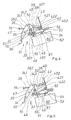
- the switching device 10 On its front side, which points upwards in FIG. 1, the switching device 10 according to the invention has two switching handles 22, which are coupled to one another by means of a connecting part 23 placed thereon, as a manual actuating element with which the contact points of the switching device 10, not shown in this illustration, can be actuated manually .
- the switching device 10 On its rear side, which points downward in FIG. 1, the switching device 10 has a recess 24, which is used to hold a mounting rail, not shown, preferably a top-hat mounting rail.
- the recess 24 open towards the flat sides is limited on the one hand towards the narrow sides by a fixed latching lug 26 which serves to support an edge of the mounting rail.
- the recess 24 is delimited by a transverse edge 25 which is penetrated in a known manner by a movable locking slide 28 which engages behind the other edge of the mounting rail.
- a movable locking slide 28 which engages behind the other edge of the mounting rail.
- the switching device 10 composed of two individual switches 12, 14 is held together by connecting elements 17 and thus forms a unitary block, which is additionally provided by a coupling part (not shown in this illustration), which serves for the mechanical coupling of the switching elements of the two individual switches 12, 14. is also standardized in its function.
- the individual switches 12, 14 combined to the switching device 10 according to the invention each have a main switching mechanism in the interior of their housings 13, 15, which is connected on the one hand to the switching handle 22 and on the other hand for actuating a contact point likewise provided in each individual switch 12, 14, each of which consists of a movable and a fixed contact piece is formed.
- Such a main switching mechanism is known from EP-B1 0 144 799, which relates to a circuit breaker as used in the invention.
- Such a main switching mechanism is also provided in the residual current protection pole 14 of the switching device 10, which is also connected on the one hand to the manual control handle 22 and on the other hand is acted upon by an auxiliary switching mechanism 30 explained in FIGS. 2 to 5.
- Figures 2 to 5 show a schematic representation of individual switching positions of the auxiliary switching mechanism 30.
- FIG. 2 shows the switch-on position of the residual current protection pole 14, the contact point 31 of which is formed from a movable contact piece 30 and a fixed contact piece 32, which is only symbolically indicated, is closed.
- the movable contact piece 30 is fastened to a contact arm 34 which is pivotally mounted about a pivot point 35.
- a spring 36 is arranged on the lever arm 341 facing away from the movable contact piece 30, which spring is supported on the one hand on the housing 15 and on the other hand on the lever arm 341 of the contact arm 34.
- a switching rod 38 is articulated, the other end of which is connected to a ratchet lever 40, where it is guided in an elongated hole 401.
- the pawl lever 40 has a detent 402, which is supported in a recess 421 of a trigger lever 42.
- the trigger lever 42 is pivotally guided at one end on an axis of rotation 43 and acted on by a torsion spring, not shown, in the clockwise direction.
- the axis of rotation 43 also serves to mount the shift handle 22, which is not shown in this illustration and which is connected in an articulated manner to the joint 381 of the shift rod 38, which is guided in the elongated hole 401, via a connecting lever, also not shown.
- the previously mentioned and described parts in FIG. 2 belong to the main switching mechanism already mentioned. These parts were addressed in so far as they interact in interaction with the auxiliary switch 44 now described below.
- auxiliary switching mechanism 44 which enables the invention, which has a rocker switch 46 with a fulcrum 45, an energy store 48 with a fulcrum 47, a latching lever 50 also with the fulcrum 47, a release rod 52, which is articulated in a fulcrum 51 in the latching lever 50, and a return spring 54, which has a fulcrum 53, and a return spring 56, which acts on the short lever arm 461 of the release rocker 46 in a clockwise direction .
- a fault current release 60 with a release plunger 61 is arranged directly adjacent to the auxiliary switching mechanism 44.
- both the main switching mechanism and the auxiliary switching mechanism 44 are in the balance of the forces.
- the contact arm 34 of the movable contact piece 30 is supported on the pawl lever 40 via the switching rod 38. Due to the special position of the pawl lever 40 shown in FIG. 2, at which its fulcrum 41, which is partially covered by the latching lever 50, below the connecting straight line from the supporting edge 421 of the release lever 42 to the other articulation point 382 of the switching rod 38 arranged in the contact arm 34 lies, the hinge point 381 is fixed to the end of the elongated hole 401 facing away from the latch 402. As already mentioned, the pawl lever 40 is supported on the support edge 421 in the release lever 42 by the action of a spring with its latching lug 402.
- the auxiliary switching mechanism 44 is also in equilibrium in the illustration shown in FIG. 2.
- the short lever arm 461 of the trigger rocker 46 is pressed by the spring 56 into the latching lever 50, so that a pawl 501 formed thereon is supported on the end face of the trigger rocker 46.
- the energy accumulator 48 which is designed as a torsion spring, is supported with its one lever arm on the housing 15 or on the guide of the auxiliary switching mechanism 44 and with its other one on the pivot pin 51 formed on the latching lever 50, to which the trigger rod 52 is articulated.
- FIG. 3 shows an intermediate position between the on and the off position of the switching system of the residual current protection pole 14 formed from the main switching mechanism and auxiliary switching mechanism 44, in which the residual current release 60 was activated as a result of the occurrence of a residual current and its switching plunger 61 has pivoted the rocker switch 46 counterclockwise from its normal position.
- the short lever arm 461 of the trigger rocker 46 pivots counterclockwise, so that the pawl 501 of the latch lever 50 loses its support and also pivots counterclockwise under the action of the energy accumulator 48 about the axis of rotation 47.
- the return spring 56 is tensioned.
- FIG. 4 shows a further intermediate position of the previously described switching arrangement.
- the pawl lever 40 has carried out a pivoting movement of approximately 30 °.
- the shift rod 38 can slide to the right in the direction of the latch 402 of the ratchet lever 40 with its pivot point 381 in the elongated hole 401 of the ratchet lever 40, this movement being supported by the spring 36 which acts on the upper lever arm 341 of the contact arm 34.
- the contact arm 34 pivots clockwise about the axis of rotation 35, as a result of which the movable contact piece 30 lifts off the fixed contact piece 32 and the contact point 31 is open.
- the lever arm 341 of the contact arm 34 presses with its end designed as a shoulder 342 against the latching lever 40, which in turn carries out a pivoting movement in a clockwise direction about the pivot axis 47.
- the latch lever 40 When it pivots clockwise around its pivot point 41, which is covered by the latch lever 50 in FIG. 4, the latch lever 40, with its free end, which carries the latch 402, acts on the return spring 54 in such a way that it pivots about the pivot point 53 the release plunger 61 of the residual current release 60 returns to its rest position.
- the return spring 54 is designed as a resilient lever, the embodiment shown in the example offering itself as a fork lever.
- the resilient resilience is necessary to ensure that the movable armature connected to the trigger plunger in the residual current release 60 actually lies in its rest position on the magnetic yoke of the residual current release and thus assumes its rest position.
- the resilient flexibility of the return spring 54 allows a certain amount of overpressure, which at the same time enables the compensation of manufacturing or wear-related tolerances.
- FIG. 5 shows the switch-off position of the fault current pole 14, in which the movable contact piece 30 is lifted off the fixed contact piece 32, but the auxiliary switching mechanism 44 is already fully tensioned again.
- the shoulder 342 of the contact arm 34 is still in contact with the latching lever 50 and acts on it in a clockwise direction, so that its pawl 501 is at a certain distance from the end face of the rocker switch 46.
- the free end of the trigger rod 52 does not lie directly on the trigger lever 42 but on an extension 422 which serves to guide the trigger rod 52.
- the detent 402 of the pawl lever 40 has again taken its place in the recess with the support edge 421 in the release lever 42. Only the shift rod 38 lies with its articulation point 381 within the elongated hole 401 above the position which it assumes in the switched-on state.
- the following summary is intended to illustrate the function of the auxiliary switching mechanism 44 used in the switching device 10 according to the invention in its residual current protective pole 14 with a compact residual current release 60.
- the residual current protection pole 14 of the switching device 10 according to the invention has a main switching mechanism that is identical to that of the adjacent circuit breaker 12. While in the circuit breaker for actuation, d. H.
- an overcurrent and a short-circuit current release are provided in a known manner, the triggering forces of which are sufficient to trigger the switching mechanism which is acted upon by a strong energy accumulator for the purpose of quick opening, such a space is not located in the fault current protection pole 14 of the switching device 10 because of the reasons mentioned at the beginning available, but only a residual current release 60 adapted to the module dimensions can be used. Due to its size, however, this residual current release 60 is not able to release enough energy to trigger the main switching mechanism in a manner comparable to that of the circuit breaker 12.
- auxiliary switching mechanism 44 which serves to amplify the low tripping force of the residual current release 60 almost without delay and to transmit it to the main switching mechanism in response to triggering it.
- the invention makes use of the interaction of lever arms and energy stores.
- the trigger rocker 46 has a long and a short lever arm 461 and can be pivoted about the pivot point 45.
- the trigger plunger 61 of the residual current release 60 acts on the long lever arm of the trigger rocker 46 in such a way that it carries out a pivoting movement counterclockwise about the axis of rotation 45 and thereby the short lever arm 461 loses its support function for the latch lever 50, which in turn is acted upon by an energy accumulator 48.
- the latch lever 50 executes a pivoting movement in the counterclockwise direction due to the action by the energy store 48 and in doing so presses the release lever 42 of the main switching mechanism out of its rest position via a release rod 52, so that the latch lever 40 supported therein is unlatched and, following the action by a spring, likewise pivots clockwise.
- the hinge point 381 of the shift rod 38 fixed up to that point in the elongated hole 401 can slide therein guided by the elongated hole 401.
- the movable contact piece 30, which is attached to the contact arm 34 lifts off from the fixed contact piece 32, so that the contact point 31 of the residual current protection pole 14 is open.
- axis of rotation 43 of the release lever 42 also represents the axis of rotation for the manual control handle 22, which couples both main switching mechanisms via the connecting part 23, so that manual actuation of the contact points is also possible.
- the residual current protection pole 14 has a test button 16, by means of which a residual current signal can be artificially generated, which leads to the response of the residual current release, which also triggers the switching mechanism in the manner described above.
- the residual current protection pole 14 is connected to the adjacent circuit breaker 12 via a coupling part (not shown in more detail), which serves to trigger the other switch pole in the event of one switch pole also tripping, so that in every response, be it an Uber or short circuit - or fault current, both individual switches 12, 14 are triggered, so that the circuit protected by the switching device 10 according to the invention is switched off.
Abstract
Description
Die Erfindung betrifft ein elektrisches Schaltgerät gemäß dem Oberbegriff des Anspruches 1.The invention relates to an electrical switching device according to the preamble of claim 1.
Elektrische Schaltgeräte zum Aufschnappen auf Profiltragschienen kommen vielfach in Niederspannungsinstallationsverteilungen zum Einsatz und dienen dort zur Absicherung einzelner Stromkreise. Hierbei sind üblicherweise für jeden abzusichernden Stromkreis Leitungsschutzschalter vorgesehen, deren Phasen über einen gemeinsamen Fehlerstromschutzschalter zwecks Abschaltung beim Auftreten von Fehlerströmen geleitet sind. In Einzelfällen kann es hierbei erforderlich sein, daß einzelne Stromkreise separat sowohl gegen Über- und Kurzschlußströme als auch gegen Fehlerströme abgesichert sind. In derartigen Fällen ist vorgesehen, daß ein separater Fehlerstromschutzschalter die Phasen des betreffenden Stromkreises erfaßt und im Ansprechfalle, d. h. bei Auftreten eines Fehlerstromes, unverzüglich den Stromkreis unterbricht.Electrical switchgear for snapping onto mounting rails are often used in low-voltage distribution boards and are used to protect individual circuits. In this case, circuit breakers are usually provided for each circuit to be protected, the phases of which are conducted via a common residual current circuit breaker for the purpose of switching off when fault currents occur. In individual cases it may be necessary for individual circuits to be separately protected against overcurrent and short-circuit currents as well as against fault currents. In such cases, it is provided that a separate residual current circuit breaker detects the phases of the circuit in question and immediately interrupts the circuit in the event of a response, ie if a fault current occurs.
Der verfügbare Raum in Niederspannungsverteilungen, insbesondere in Zählerplätzen, ist häufig knapp und erfordert daher eine bestmögliche Raumausnutzung. Bekannte, zum Aufschnappen auf Tragschienen vorgesehene Fehlerstromschutzschalter (DE-OS 25 08 428), die einpolig oder mehrpolig vorgesehen sein können, weisen Gehäuseabmessungen auf, für die an der Tragschiene Platz freizuhalten ist, der normalerweise für wenigstens zwei übliche Reiheneinbaugeräte in modularer Schmalbauweise, z. B. Leitungsschutzschalter (EP 0 144 799 B1), ausreicht.The space available in low-voltage distributions, especially in metering stations, is often scarce and therefore requires the best possible use of space. Known, for snapping on mounting rails residual current circuit breaker (DE-OS 25 08 428), which can be provided single-pole or multi-pole, have housing dimensions for which space is to be kept free on the mounting rail, which is normally used for at least two conventional modular devices in modular narrow construction, e.g. . B. circuit breaker (EP 0 144 799 B1) is sufficient.
Ein elektrisches Schaltgerät der eingangs genannten Art ist aus der FR-A 2 409 592 bekannt geworden. Der Fehlerstromauslöser in diesem Schaltgerät betätigt über eine Blattfeder das Schaltwerk, so daß vom Auslöser selbst diejenige Kraft aufgewendet werden muß, die zur Auslösung erforderlich ist. Darüberhinaus besitzt das Fehlerstromteil keine eigene Kontaktstelle.An electrical switching device of the type mentioned is known from FR-A 2 409 592. The residual current release in this switching device actuates the switching mechanism via a leaf spring, so that the trigger itself must exert the force required to trigger it. In addition, the fault current section does not have its own contact point.
Ein Fehlerstromschutzschalter, bei dem eine Kontaktstelle vorgesehen ist, ist aus der FR-A 2 553 572 bekannt geworden. Allerdings ist nirgendwo angegeben, wie dieses Schaltgerät mit einem Leitungsschutzschalter zusammengebaut werden soll.A residual current circuit breaker in which a contact point is provided has become known from FR-A 2 553 572. However, nowhere is it specified how this switchgear should be assembled with a circuit breaker.
Aufgabe der Erfindung ist es, ein elektrisches Schaltgerät der eingangs genannten Art zu schaffen, welches bei möglichst geringem Platzbedarf und kostengünstiger Herstellbarkeit auch einen relativ kleinen Fehlerstromauslöser benötigt.The object of the invention is to provide an electrical switching device of the type mentioned, which also requires a relatively small residual current release with the smallest possible space requirement and inexpensive to manufacture.
Diese Aufgabe wird erfindungsgemäß gelöst durch die kennzeichnenden Merkmale des Anspruches 1.This object is achieved according to the invention by the characterizing features of claim 1.
Mit Hilfe der vorhandenen Kupplung zwischen den beiden Hauptschaltwerken des Leitungsschutzschalters und des Fehlerstromschutzschalters wird mit Auslösung des Fehlerstrompoles gleichzeitig auch der benachbarte Leitungsschutzschalterpol beaufschlagt und dessen Kontaktstelle geöffnet.With the help of the existing coupling between the two main switchgear of the circuit breaker and the When the residual current circuit breaker is triggered, the residual current circuit breaker is also applied to the adjacent circuit breaker pole and its contact point is opened.
Die erfindungsgemäß vorgesehene Unterbringung des Fehlerstromschutzschalters in einem Gehäuse mit der Breite eines üblichen Schaltermoduls (17,5 mm) wird dadurch ermöglicht, daß gegenüber den bekannten Fehlerstromschutzschaltern ein besonders kompakter Fehlerstromauslöser Verwendung findet, dessen äußere Abmessungen es zulassen, ihn in einem solchen Gehäuse unterzubringen. Die bisher in üblichen Fehlerstromschutzschaltern eingesetzten Fehlerstromauslöser weisen allesamt jeweils größere Abmessungen auf, die es nicht gestatten, ein derart schmales Gehäuse zur Unterbringung aller erforderlichen Schalterbauteile vorzusehen. Die räumliche Größe der bekannten Fehlerstromauslöser hängt mit der erforderlichen Auslösekraft zusammen, die zur Betätigung der Schaltkontakte benötigt wird. Statt eines entsprechend groß dimensionierten Fehlerstromauslösers wird bei der Erfindung ein anderer Weg beschritten, um die Öffnung der Kontaktstellen zu erreichen ohne Verlust an Öffnungsgeschwindigkeit der Kontaktstücke. Die Größe und damit die Auslösekraft des Fehlerstromauslösers wird gemäß der Erfindung dadurch kompensiert, daß ein Hilfsschaltwerk zwischen Auslöser und Hauptschaltwerk geschaltet ist, welches den Impuls des im Ansprechfall betätigten Auslösestößels des Fehlerstromauslösers aufnimmt und verstärkt an das Hauptschaltwerk weiterleitet.The inventive arrangement of the residual current circuit breaker in a housing with the width of a conventional switch module (17.5 mm) is made possible in that a particularly compact residual current release is used compared to the known residual current circuit breakers, the external dimensions of which allow it to be accommodated in such a housing. The residual current releases previously used in conventional residual current circuit breakers each have larger dimensions, which do not allow the provision of such a narrow housing for accommodating all the necessary switch components. The spatial size of the known residual current release is related to the release force required to actuate the switch contacts. Instead of a correspondingly large-sized residual current release, another way is taken in the invention to achieve the opening of the contact points without loss of the opening speed of the contact pieces. The size and thus the triggering force of the residual current release is compensated for in accordance with the invention in that an auxiliary switching mechanism is connected between the trigger and the main switching mechanism, which picks up the pulse of the triggering plunger of the residual current trigger which is actuated in response and transmits it increasingly to the main switching mechanism.
In bevorzugter Ausgestaltung der Erfindung ist vorgesehen, das Hilfsschaltwerk mit einem Auslösehebel zu versehen, der eine von einem Energiespeicher beaufschlagte Klinke abstützt, die mittels eines Ubertragungshebels mit einem Klinkenhebel des Hauptschaltwerks zusammenarbeitet. Der Auslösehebel ist als Wippe gestaltet, die um einen Drehpunkt schwenkbar ist. Der kürzere Hebelarm der Schalt- oder Auslösewippe arbeitet mit der Klinke zusammen, während sein längerer Hebelarm vom Auslösestößel des Fehlerstromauslösers beaufschlagbar ist. Außerdem weist das Hilfsschaltwerk eine Rückstellfeder mit Uberdrückung zur Rückstellung des Auslösenockens des Fehlerstromauslösers auf. Mit Hilfe dieser Rückstellfeder kann der Auslösestößel und mit ihm ein im Fehlerstromauslöser angeordneter beweglicher Anker nach erfolgter Auslösung in seine Ausgangslage zurückgesetzt werden.In a preferred embodiment of the invention, the auxiliary switching mechanism is provided with a release lever which supports a pawl which is acted upon by an energy store and which works together with a ratchet lever of the main switching mechanism by means of a transmission lever. The release lever is designed as a rocker that can be pivoted about a pivot point. The shorter lever arm of the switching or trigger rocker works together with the pawl, while its longer lever arm can be acted on by the trigger plunger of the residual current device. In addition, the auxiliary switching mechanism has a return spring with overpressure for resetting the tripping cam of the residual current release. With the help of this return spring, the trigger plunger and with it a movable armature arranged in the residual current release can be reset to its initial position after the triggering.
Erfindungsgemäß ist für das Hauptschaltwerk des Fehlerstrompoles das gleiche Schaltwerk vorgesehen, wie es im Leitungsschutzpol zum Einsatz kommt. Hieraus resultieren erhebliche wirtschaftliche Vorteile, da die Herstellung dieses Schaltwerkes in großen Serien auf entsprechenden Maschinen automatisch erfolgt, was zu günstigen Herstellkosten führt und eine weitgehend automatisierte Fertigung des kombinierten elektrischen Schaltegrätes gestattet.According to the invention, the same switching mechanism as is used in the line protection pole is provided for the main switching mechanism of the fault current pole. This results in considerable economic advantages, since the production of this switching mechanism is carried out automatically in large series on corresponding machines, which leads to low manufacturing costs and permits a largely automated production of the combined electrical switching device.
Gemäß einer besonders vorteilhaften Ausgestaltung der Erfindung ist es vorgesehen, das Hilfsschaltwerk mitsamt dem Fehlerstromauslöser dicht neben dem Hauptschaltwerk zu plazieren, um so genügend Raum im Gehäuse des Fehlerstromschutzschalters zur Verfügung zu haben, der zur Unterbringung der Auswerteeinheit sowie der Kontaktstelle und der dieser zugeordneten Lichtbogenlöscheinrichtung erforderlich ist.According to a particularly advantageous embodiment of the invention, it is provided to place the auxiliary switch together with the residual current release close to the main switch so that there is enough space in the housing of the residual current circuit breaker to accommodate the evaluation unit as well as the contact point and the arc extinguishing device assigned to it is.
In vorteilhafter Ausgestaltung der Erfindung kann ferner vorgesehen sein, die wenigen Einzelteile des Hilfsschaltwerkes zusammen mit dem Fehlerstromauslöser auf einer gemeinsamen Platine anzuordnen, was die Montage der Auslöseeinheit vereinfacht und deren Funktionssicherheit erhöht. Andererseits ist es jedoch auch möglich, die einzelnen vorgenannten Teile des Hilfsschaltwerkes sowie den Fehlerstromauslöser mit Hilfe von entsprechend an der Gehäusewand angeformten Ansätzen, Zapfen und Lagerungen zu fixieren. Für diese Variante spricht die Möglichkeit der Herstellung eines derartigen Gehäuses in einem Arbeitsgang als Spritzgußteil.In an advantageous embodiment of the invention, it can further be provided to arrange the few individual parts of the auxiliary switching mechanism together with the residual current release on a common circuit board, which simplifies the assembly of the tripping unit and increases its functional reliability. On the other hand, however, it is also possible to fix the individual aforementioned parts of the auxiliary switching mechanism as well as the residual current release with the help of projections, pins and bearings which are molded onto the housing wall. This variant is supported by the possibility of producing such a housing in one operation as an injection molded part.
Diese und weitere vorteilhafte Ausgestaltungen der Erfindung sind in den Unteransprüchen angegeben.These and further advantageous refinements of the invention are specified in the subclaims.
Anhand in der Zeichnung dargestellten Ausführungsbeispieles sollen vorteilhafte Ausgestaltungen und besondere Vorteile der Erfindung näher erläutert und beschrieben werden.On the basis of the exemplary embodiment shown in the drawing, advantageous configurations and particular advantages of the invention are to be explained and described in more detail.
Es zeigen:
- Figur 1
- Ein erfindungsgemäßes Schaltgerät (FI/LS-Schalter) in Schrägansicht
- Figur 2 bis 5
- ein Hilfsschaltwerk mit Fehlerstromauslöser des erfindungsgemäßen Schaltgerätes in schematischer Darstellung
- Figur 2
- Einschaltstellung
- Figur 3
- eine Zwischenstellung
- Figur 4
- eine Zwischenstellung mit abgehobenen beweglichen Kontaktstück und Rückstellung des Hilfsschaltwerks und des Fehlerstromauslösers
- Figur 5
- Ausschaltstellung
- Figure 1
- An inventive switching device (FI / LS switch) in an oblique view
- Figure 2 to 5
- an auxiliary switch with residual current release of the switching device according to the invention in a schematic representation
- Figure 2
- ON position
- Figure 3
- an intermediate position
- Figure 4
- an intermediate position with the movable contact piece lifted off and the auxiliary switching mechanism and the residual current release reset
- Figure 5
- OFF position
In Figur 1 ist ein erfindungsgemäßes Schaltgerät 10 dargestellt, das aus je einem Leitungsschutzschalter 12 und einem Fehlerstromschutzschalter 14, die in separaten nebeneinander angeordneten modulartigen Gehäusen 13, 15 angeordnet sind, zusammengesetzt ist. Die beiden Gehäuse 13, 15 sind äußerlich nahezu gleich, was ihre äußeren Abmessungen betreffen - die Dicke der Gehäuse entspricht dem festgelegten Modulmaß von 17,5 mm -, als auch hinsichtlich ihrer Formgebung mit Ausnahme einer Prüftaste 16, mittels der die Funktion des Fehlerstrompoles 14 überprüfbar ist. Im übrigen besitzen beide Einzelschalter 12, 14 jeweils durch Betätigungsöffnungen 18 betätigbare nicht gezeigte Anschlußklemmen, die über Zuführungsöffnungen 20 für den Anschluß von Zuführungs- und Abgangsleitern erreichbar sind.In Figure 1, a
An seiner Frontseite, die in der Figur 1 nach oben weist, besitzt das erfindungsgemäße Schaltgerät 10 zwei Schaltgriffe 22, die mittels eines daraufgesetzten Verbindungsteiles 23 miteinander gekoppelt sind, als Handbetätigungsorgan, mit welchem die in dieser Darstellung nicht gezeigten Kontaktstellen des Schaltgerätes 10 manuell betätigbar sind. An seiner in Figur 1 nach unten weisenden Rückseite weist das Schaltgerät 10 eine Ausnehmung 24 auf, welche zur Aufnahme einer nicht dargestellten Tragschiene, vorzugsweise Hutprofiltragschiene, dient. Die nach den Flachseiten hin offene Ausnehmung 24 wird nach den Schmalseiten hin einerseits von einer ortsfesten Rastnase 26 begrenzt, welche zur Abstützung einer Kante der Tragschiene dient. Zur anderen Schmalseite hin wird die Ausnehmung 24 von einer Querkante 25 begrenzt, die in bekannter Weise von einem beweglichen Rastschieber 28 durchgriffen ist, der die andere Kante der Tragschiene hintergreift. Von dem Rastschieber 38 ist in Figur 1 allerdings nur das Ende mit einer Betätigungsöffnung 29 zu erkennen.On its front side, which points upwards in FIG. 1, the
Das wie bereits erwähnt aus zwei Einzelschaltern 12, 14 zusammengesetzte Schaltgerät 10 ist durch Verbindungselemente 17 zusammengehalten und bildet so einen einheitlichen Block, der zusätzlich durch ein in dieser Darstellung nicht erkennbares Kupplungsteil, welches zur mechanischen Kopplung der Schaltorgane der beiden Einzelschalter 12, 14 dient, auch in seiner Funktion vereinheitlicht ist. Die zum erfindungsgemäßen Schaltgerät 10 vereinigten Einzelschalter 12, 14 besitzen jeweils im Inneren ihrer Gehäuse 13, 15 ein Hauptschaltwerk, das einerseits mit dem Schaltgriff 22 verbunden ist und andererseits zur Betätigung einer ebenfalls in jedem Einzelschalter 12, 14 vorgesehenen Kontaktstelle, die jeweils aus einem beweglichen und einem festen Kontaktstück gebildet ist. Ein solches Hauptschaltwerk ist bekannt aus der EP-B1 0 144 799, die einen Leitungsschutzschalter betrifft, wie er bei der Erfindung Verwendung findet. Im Fehlerstromschutzpol 14 des Schaltgerätes 10 ist ebenfalls ein solches Hauptschaltwerk vorgesehen, welches ebenfalls einerseits mit dem Handschaltgriff 22 verbunden ist und andererseits aber von einem in den Figuren 2 bis 5 erläuterten Hilfsschaltwerk 30 beaufschlagt ist. Die Figuren 2 bis 5 geben in schematischer Darstellung einzelne Schaltstellungen des Hilfsschaltwerks 30 wieder.As already mentioned, the switching
In Figur 2 ist die Einschaltstellung des Fehlerstromschutzpoles 14 dargestellt, dessen aus einem beweglichen Kontaktstück 30 und einem nur symbolisch angedeuteten festen Kontaktstück 32 gebildete Kontaktstelle 31 geschlossen ist. Das bewegliche Kontaktstück 30 ist an einem Kontaktarm 34 befestigt, der um einen Drehpunkt 35 schwenkbar gelagert ist. Oberhalb des Drehpunktes 35 des Kontaktarmes 34, d. h. an dessen dem beweglichen Kontaktstück 30 abgewandten Hebelarm 341 ist eine Feder 36 angeordnet, welche sich einerseits am Gehäuse 15 und andererseits am Hebelarm 341 des Kontaktarmes 34 abstützt. Am Ende des Hebelarmes 341 des Kontaktarmes 34 ist eine Schaltstange 38 angelenkt, deren anderes Ende mit einem Klinkenhebel 40 verbunden ist, wo es in einem Langloch 401 geführt ist. Der Klinkenhebel 40 besitzt eine Rastnase 402, welche sich in einer Ausnehmung 421 eines Auslösehebels 42 abstützt. Der Auslösehebel 42 ist an einem Ende an einer Drehachse 43 schwenkbar geführt und von einer nicht dargestellten Drehfeder im Uhrzeigersinn beaufschlagt. Die Drehachse 43 dient gleichzeitig auch zur Lagerung des Schaltgriffes 22, der in dieser Darstellung nicht gezeigt ist und der über einen ebenfalls nicht dargestellten Verbindungshebel mit dem im Langloch 401 geführten Gelenk 381 der Schaltstange 38 gelenkig verbunden ist. Die bisher erwähnten und beschriebenen Teile in Figur 2 gehören zum bereits erwähnten Hauptschaltwerk. Diese Teile wurden insoweit angesprochen, als sie in Wechselwirkung mit dem nun anschließend beschriebenen Hilfsschaltwerk 44 zusammenwirken.FIG. 2 shows the switch-on position of the residual
Die im folgenden behandelten Teile gehören zum die Erfindung ermöglichenden Hilfsschaltwerk 44, welches eine Schaltwippe 46, mit einem Drehpunkt 45, einen Kraftspeicher 48 mit einem Drehpunkt 47, einen Verklinkungshebel 50 ebenfalls mit dem Drehpunkt 47, eine Auslösestange 52, die in einem Drehpunkt 51 im Verklinkungshebel 50 gelenkig geführt ist, sowie eine Rückstellfeder 54, die einen Drehpunkt 53 besitzt, und eine Rückholfeder 56, welche den kurzen Hebelarm 461 der Auslösewippe 46 im Uhrzeigersinn beaufschlagt. Unmittelbar benachbart zum Hilfsschaltwerk 44 ist ein Fehlerstromauslöser 60 mit einem Auslösestößel 61 angeordnet.The parts dealt with below belong to the
Im eingeschalteten Zustand befinden sich sowohl das Hauptschaltwerk als auch das Hilfsschaltwerk 44 im Gleichgewicht der Kräfte. Dabei stützt sich der Kontaktarm 34 des beweglichen Kontaktstückes 30 über die Schaltstange 38 am Klinkenhebel 40 ab. Aufgrund der besonderen, in Figur 2 gezeigten Lage des Klinkenhebels 40, bei der dessen Drehpunkt 41, der durch den Verklinkungshebel 50 teilweise verdeckt ist, unterhalb der Verbindungsgeraden von der Stützkante 421 des Auslösehebels 42 zu dem im Kontaktarm 34 angeordneten anderen Gelenkpunkt 382 der Schaltstange 38 liegt, ist deren Gelenkpunkt 381 an dem der Rastnase 402 abgewandten Ende des Langlochs 401 fixiert. Wie bereits erwähnt, stützt sich der Klinkenhebel 40 aufgrund der Beaufschlagung durch eine Feder mit seiner Rastnase 402 an der Stützkante 421 im Auslösehebel 42 ab.In the switched-on state, both the main switching mechanism and the
Auch das Hilfsschaltwerk 44 ist in der gezeigten Darstellung in Figur 2 im Gleichgewicht. Der kurze Hebelarm 461 der Auslösewippe 46 wird von der Feder 56 in den Verklinkungshebel 50 gedrückt, so daß eine an diesen angeformte Klinke 501 sich an der Stirnseite der Auslösewippe 46 abstützt. Der Kraftspeicher 48, der als Drehfeder ausgestaltet ist, stützt sich mit seinem einen Hebelarm am Gehäuse 15 oder an der Führung des Hilfsschaltwerkes 44 ab und mit seinem anderen an dem an den Verklinkungshebel 50 angeformten Drehzapfen 51, an welchen die Auslösestange 52 angelenkt ist.The
Solange keine äußeren Einflüsse auf dieses aus dem Hauptschaltwerk und dem Hilfsschaltwerk 44 gebildete Hebelsystem einwirken, bleibt der beschriebene Zustand erhalten und die Kontaktstelle 31 geschlossen.As long as there are no external influences on this lever system formed from the main switching mechanism and the
In Figur 3 ist eine Zwischenstellung zwischen der Einund der Ausschaltstellung des aus Hauptschaltwerk und Hilfsschaltwerk 44 gebildeten Schaltwerksystems des Fehlerstromschutzpoles 14 gezeigt, bei der infolge Auftreten eines Fehlerstromes der Fehlerstromauslöser 60 aktiviert wurde und sein Schaltstößel 61 die Schaltwippe 46 aus ihrer Normallage im Gegenuhrzeigersinn verschwenkt hat. Hierdruch schwenkt auch der kurze Hebelarm 461 der Auslösewippe 46 im Gegenuhrzeigersinn, so daß die Klinke 501 des Verklinkungshebels 50 ihre Stütze verliert und ebenfalls im Gegenuhrzeigersinn unter Einwirkung des Kraftspeichers 48 um die Drehachse 47 schwenkt. Mit dem Schwenken der Auslösewippe 46 wird die Rückholfeder 56 gespannt.FIG. 3 shows an intermediate position between the on and the off position of the switching system of the residual
Einhergehend mit der Schwenkbewegung des Verklinkungshebels 50 um die Drehachse 47 verschiebt sich auch das Drehgelenk 51 der Auslösestange 52 in Richtung auf den Auslösehebel 42 zu. Hierdurch erfährt auch der Auslösehebel 42 eine Schwenkbewegung im Gegenuhrzeigersinn um seine Drehachse 43. Dadurch wird der Rastnase 402 die Stütze an der Stützkante 421 entzogen und kann entsprechend der Beaufschlagung durch die Feder 36 über die Schaltstange 38 im Uhrzeigersinn schwenken. Dieser Vorgang ist in Figur 4 dargestellt.Along with the pivoting movement of the latching
Figur 4 zeigt eine weitere Zwischenstellung der zuvor beschriebenen Schaltwerksanordnung. Wie in der Beschreibung zu Figur 3 bereits erwähnt, hat der Klinkenhebel 40 eine Schwenkbewegung um ca. 30° ausgeführt. Hierdurch kann die Schaltstange 38 nach rechts in Richtung auf die Rastnase 402 des Klinkenhebels 40 zu mit seinem Gelenkpunkt 381 in dem Langloch 401 des Klinkenhebels 40 gleiten, wobei diese Bewegung durch die Feder 36, die den oberen Hebelarm 341 des Kontaktarmes 34 beaufschlagt unterstützt wird. Einhergehend mit dieser Axialverschiebung der Schaltstange 38 vollzieht der Kontaktarm 34 eine Schwenkbewegung im Uhrzeigersinn um die Drehachse 35, wodurch das bewegliche Kontaktstück 30 vom festen Kontaktstück 32 abhebt und die Kontaktstelle 31 geöffnet ist. Gleichzeitig mit dieser Schwenkbewegung drückt der Hebelarm 341 des Kontaktarmes 34 mit seinem als Schulter 342 ausgebildeten Ende gegen den Verklinkungshebel 40, wodurch dieser wiederum eine Schwenkbewegung im Uhrzeigersinn um die Schwenkachse 47 vollzieht.Figure 4 shows a further intermediate position of the previously described switching arrangement. As already mentioned in the description of FIG. 3, the
Bei dieser Schwenkbewegung des Verklinkungshebels 40 vollzieht sich zweierlei. Zum einen wird der Kraftspeicher 48 durch den Drehzapfen 51 erneut gespannt. Gleichzeitig wird auch die Klinke 501 im Uhzeigersinn geschwenkt, so daß auch der kurze Hebelarm 461 der Schaltwippe 46 aufgrund der Beaufschlagung durch die Rückholfeder 56 in seine Normallage zurückgleitet und so seine Strinseite wieder als Stütze für die Klinke 501 dienen kann. Ferner wird bei dieser Schwenkbewegung des Verklinkungshebels 40 auch die Auslösestange 52 in ihre Normallage zurückgezogen.During this pivoting movement of the
Bei seiner Schwenkbewegung im Uhrzeigersinn um seine in Figur 4 durch den Verklinkunghebel 50 verdeckten Drehpunkt 41 beaufschlagt der Klinkenhebel 40 mit seinem freien Ende, welches die Rastnase 402 trägt, die Rückholfeder 54 derart, daß diese um den Drehpunkt 53 schwenkend den Auslösestößel 61 des Fehlerstromauslösers 60 in seine Ruhelage zurückstellt.When it pivots clockwise around its
Die Rückholfeder 54 ist als federnd nachgiebiger Hebel ausgebildet, wobei sich die im Beispiel gezeigte Ausgestaltung als Gabelhebel anbietet. Die federnde Nachgiebigkeit ist erforderlich, um sicherzustellen, daß der an den Auslösestößel anschließende bewegliche Anker im Fehlerstromauslöser 60 auch tatsächlich in seine Ruhelage am Magnetjoch des Fehlerstromauslösers anliegt und so seine Ruhelage einnimmt. Hierbei gestattet die federnde Nachgiebigkeit der Rückstellfeder 54 eine gewisse Uberdrückung, die gleichzeitig den Ausgleich von fertigungs- bzw. verschleißbedingten Toleranzen ermöglicht.The
In Figur 5 ist schließlich die Ausschaltstellung des Fehlerstrompoles 14 wiedergegeben, in der das bewegliche Kontaktstück 30 vom festen Kontaktstück 32 abgehoben ist jedoch das Hilfsschaltwerk 44 bereits wieder voll gespannt ist. Hierbei ist zu beachten, daß die Schulter 342 des Kontaktarmes 34 nach wie vor im Kontakt mit dem Verklinkungshebel 50 steht und diesen in Uhrzeigersinn beaufschlagt, so daß dessen Klinke 501 in gewissem Abstand zur Stirnseite der Schaltwippe 46 steht. Desgleichen liegt auch das freie Ende der Auslösestange 52 nicht unmittelbar am Auslösehebel 42 an sondern an einem Ansatz 422, der zur Führung der Auslösestange 52 dient.Finally, FIG. 5 shows the switch-off position of the fault
Die Rastnase 402 des Klinkenhebels 40 hat wieder ihren Platz in der Ausnehmung mit der Stützkante 421 im Auslösehebel 42 eingenommen. Lediglich die Schaltstange 38 liegt mit ihrem Gelenkpunkt 381 innerhalb des Langloches 401 oberhalb der Lage, die sie im eingeschalteten Zustand einnimmt.The
Um die Funktion des im erfindungsgemäßen Schaltgerätes 10 in dessen Fehlerstromschutzpol 14 eingesetzten Hilfsschaltwerkes 44 mit kompaktem Fehlerstromauslöser 60 zu verdeutlichen, soll nachfolgende Zusammenfassung dienen. Der Fehlerstromschutzpol 14 des erfindungsgemäßen Schaltgerätes 10 besitzt ein Hauptschaltwerk, daß mit dem des benachbarten Leitungsschutzschalters 12 identisch ist. Während im Leitungsschutzschalter zur Betätigung, d. h. zur Auslösung, des Schaltwerkes in bekannter Weise ein Uberstrom- sowie ein Kurzschlußstromauslöser vorgesehen sind, deren Auslösekräfte ausreichen, um das zwecks schneller Öffnung von einem starken Kraftspeicher beaufschlagte Schaltwerk auszulösen, steht im Fehlerstromschutzpol 14 des Schaltgerätes 10 wegen der eingangs genannten Gründe ein derartiger Raum nicht zur Verfügung, sondern es kann lediglich ein den Modulabmessungen angepaßter Fehlerstromauslöser 60 zum Einsatz kommen. Dieser Fehlerstromauslöser 60 jedoch ist bedingt durch seine Größe nicht in der Lage, soviel Energie freizusetzen, um das Hauptschaltwerk in vergleichbarer Weise wie beim Leitungsschutzschalter 12 auszulösen.The following summary is intended to illustrate the function of the
Demzufolge ist erfindungsgemäß vorgesehen, ein Hilfsschaltwerk 44 zwischenzuschalten, das dazu dient die geringe Auslösekraft des Fehlerstromauslösers 60 nahezu verzögerungsfrei zu verstärken und im Ansprechfall auf das Hauptschaltwerk zu übertragen, um es zur Auslösung zu bringen. Hierbei macht sich die Erfindung die Wechselwirkung von Hebelarmen und Kraftspeichern zu Nutze.Accordingly, it is provided according to the invention to interpose an
Die Auslösewippe 46 besitzt einen langen und einen kurzen Hebelarm 461 und ist um den Drehpunkt 45 schwenkbar. Im Ansprechfall beaufschlagt der Auslösestößel 61 des Fehlerstromauslösers 60 den langen Hebelarm der Auslösewippe 46 derart, daß diese eine Schwenkbewegung im Gegenuhrzeigersinn um die Drehachse 45 ausführt und dabei der kurze Hebelarm 461 seine Stützfunktion für den Verklinkungshebel 50, der seinerseits von einem Kraftspeicher 48 beaufschlagt ist, verliert. Hierdurch vollzieht der Verklinkungshebel 50 aufgrund der Beaufschlagung durch den Kraftspeicher 48 eine Schwenkbewegung im Gegenuhrzeigersinn und drückt hierbei über eine Auslösestange 52 den Auslösehebel 42 des Hauptschaltwerkes aus seiner Ruhelage, so daß der darin abgestützte Klinkenhebel 40 entklinkt ist und, der Beaufschlagung durch eine Feder folgend ebenfalls eine Schwenkbewegung im Uhrzeigersinn ausführt. Hierdurch kann der bis dahin in dem Langloch 401 fixierte Gelenkpunkt 381 der Schaltstange 38 vom Langloch 401 geführt darin entlanggleiten. Die am Gehäuse 15 oder an der Führung des Hilfsschaltwerkes 44 abgestützte Feder 36, die den oberen Hebelarm 341 des Kontaktarmes 34 beaufschlagt, an welchem die Schaltstange 38 angelenkt ist, unterstützt die Bewegung der Schaltstange 38, wodurch gleichzeitig der Kontaktarm 34 eine Schwenkbewegung im Uhrzeigersin um den Drehpunkt 35 ausführt. Hierbei hebt das bewegliche Kontaktstück 30, das am Kontaktarm 34 befestigt ist vom festen Kontaktstück 32 ab, so daß die Kontatkstelle 31 des Fehlerstromschutzpoles 14 geöffnet ist.The
Ergänzend ist noch darauf hinzuweisen, daß die Drehachse 43 des Auslösehebels 42 gleichzeitig auch Drehachse für den Handschaltgriff 22 darstellt, der über das Verbindungsteil 23 beide Hauptschaltwerke koppelt, so daß auch eine manuelle Betätigung der Kontaktstellen möglich ist.In addition, it should also be pointed out that the axis of
Ferner besitzt der Fehlerstromschutzpol 14 eine Prüftaste 16, mittels der ein Fehlerstromsignal künstlich erzeugt werden kann, welches zum Ansprechen des Fehlerstromauslösers führt, wodurch ebenfalls in der vorher beschriebenen Weise die Auslösung des Schaltwerkes hervorgerufen wird.Furthermore, the residual
Darüberhinaus ist der Fehlerstromschutzpol 14 mit dem benachbarten Leitungsschutzschalter 12 über ein nicht näher gezeigtes Kupplungsteil verbunden, welches dazu dient, im Auslösefalle des einen Schalterpoles jeweils den anderen Schalterpol ebenfalls zur Auslösung zu bringen, so daß in jedem Ansprechfall, sei es ein Uber-, Kurzschluß- oder Fehlerstrom, zur Auslösung beider Einzelschalter 12, 14 kommt, so daß der durch das erfindungsgemäße Schaltgerät 10 gesicherte Stromkreis stromlos geschaltet ist.In addition, the residual
Claims (10)
- Electrical switching apparatus for snapping onto profiled supporting rails having a single-pole line protection circuit breaker (12) and residual current device (14) which are arranged in housings (13, 15) which are separate but connected to one another and have a module width (of, for example, 17.5 mm), in each case having tripping means for operating moving contact elements (30) which form contact points (32) by means of stationary contact elements, and having manual switching handles (22) which in each case allow manual operation of the moving contact elements (30) via at least one switching mechanism having a latching point, the residual current device (14) and the line protection circuit breaker (12) in each case having a main switching mechanism, which main switching mechanisms are connected by means of a coupling, are of identical design and operate the moving contact elements (30), characterized in that both the line protection circuit breaker (12) and the residual current device (14) each have a contact point with a stationary contact element (30) and a moving contact element (32), and in that the residual current device (14) additionally has an auxiliary switching mechanism (44) which interacts with a residual current tripping device (60) and amplifies its tripping pulse, which is transmitted by a tripping plunger (61), transmits it to the tripping lever (42) of the main switching mechanism and thus brings about its unlatching, which results in the opening of the associated contact points (31).
- Electrical switching apparatus according to Claim 1, characterized in that the auxiliary switching mechanism has a latching lever (50) which is acted on by a force store (48), is for its part connected via a tripping rod (52) to the tripping lever (42) of the main switching mechanism and is supported on a tripping rocker (46) which is acted on by the tripping plunger (61) of the residual current tripping device (60).
- Electrical switching apparatus according to Claim 2, characterized in that, in the event of a response, the tripping plunger (61) of the residual current tripping device (60) causes the tripping rocker (46) to pivot in the anticlockwise direction, as a result of which the latching lever (50) loses its support and, under the influence of the force store (48) and via the tripping rod (42), moves the tripping lever (42) of the main switching mechanism out of its quiescent position and in consequence brings about the unlatching of a latching lever (40) which is connected via a switching rod (38) to a contact arm (34) which supports the moving contact element (30) and thus causes the opening of the contact point (31).
- Electrical switching apparatus according to one of the preceding claims, characterized in that the force store (48) is constructed as a rotation spring which is supported on the one side on the housing (15) or on a guide for an auxiliary switching mechanism 44 [sic] and on the other side on a rotation journal (51) which is integrally formed on the latching lever (50).
- Electrical switching apparatus according to one of the preceding claims, characterized in that a return spring (56) is provided for resetting the tripping rocker (46), which return spring (56) acts on the tripping rocker (46) such that it tries to latch with the latching lever (50).
- Electrical switching apparatus according to one of the preceding claims, characterized in that a resetting spring (54) is provided with whose aid the tripping plunger (61) of the residual current tripping device can be reset to its quiescent position.
- Electrical switching apparatus according to Claim 6, characterized in that, once tripping has been carried out, the resetting spring is acted on by the latching lever (40) of the main switching mechanism in order to reset the tripping plunger (61).
- Electrical switching apparatus according to one of the preceding claims, characterized in that the contact arm (34) has a shoulder (342) which resets the latching lever (50) to its quiescent position while the moving contact element (30) is being lifted off, and at the same time tensions the force store (48).
- Electrical switching apparatus according to one of the preceding claims, characterized in that the resetting spring is constructed as a leaf spring which is bent in a U-shape and is arranged such that it can pivot about a rotation journal (53).
- Electrical switching apparatus according to one of the preceding claims, characterized in that the switching rocker (46) is provided as a cross member having a pivoting support (45) which is arranged eccentrically with respect to its longitudinal rotation.
Priority Applications (1)
| Application Number | Priority Date | Filing Date | Title |
|---|---|---|---|
| AT88116084T ATE103416T1 (en) | 1987-10-05 | 1988-09-29 | ELECTRICAL SWITCHING DEVICE. |
Applications Claiming Priority (2)
| Application Number | Priority Date | Filing Date | Title |
|---|---|---|---|
| DE3733595 | 1987-10-05 | ||
| DE19873733595 DE3733595A1 (en) | 1987-10-05 | 1987-10-05 | ELECTRICAL SWITCHGEAR |
Publications (3)
| Publication Number | Publication Date |
|---|---|
| EP0310943A2 EP0310943A2 (en) | 1989-04-12 |
| EP0310943A3 EP0310943A3 (en) | 1990-06-20 |
| EP0310943B1 true EP0310943B1 (en) | 1994-03-23 |
Family
ID=6337628
Family Applications (1)
| Application Number | Title | Priority Date | Filing Date |
|---|---|---|---|
| EP88116084A Expired - Lifetime EP0310943B1 (en) | 1987-10-05 | 1988-09-29 | Electric switch gear |
Country Status (4)
| Country | Link |
|---|---|
| EP (1) | EP0310943B1 (en) |
| AT (1) | ATE103416T1 (en) |
| DE (2) | DE3733595A1 (en) |
| ES (1) | ES2053666T3 (en) |
Families Citing this family (4)
| Publication number | Priority date | Publication date | Assignee | Title |
|---|---|---|---|---|
| AT410726B (en) * | 1993-03-18 | 2003-07-25 | Felten & Guilleaume Ag Oester | BREAKERS |
| DE19735413B4 (en) * | 1997-08-14 | 2007-11-29 | Siemens Ag | Tripping device for a circuit breaker |
| EP0951045A3 (en) * | 1998-04-14 | 2000-07-12 | ABBPATENT GmbH | Ground fault circuit braker |
| DE102007043253B4 (en) * | 2007-09-11 | 2014-04-24 | Siemens Aktiengesellschaft | Handle bridge, residual current device and system of residual current device and circuit breaker |
Family Cites Families (8)
| Publication number | Priority date | Publication date | Assignee | Title |
|---|---|---|---|---|
| US3908154A (en) * | 1974-09-13 | 1975-09-23 | Ite Imperial Corp | Two pole ground fault circuit protector |
| DE2508428B2 (en) * | 1975-02-27 | 1978-10-12 | Brown, Boveri & Cie Ag, 6800 Mannheim | Residual current circuit breaker |
| DE2651596C3 (en) * | 1976-11-12 | 1979-05-10 | Licentia Patent-Verwaltungs-Gmbh, 6000 Frankfurt | Residual current component combined with a miniature circuit breaker |
| FR2409592A1 (en) * | 1977-11-21 | 1979-06-15 | Legrand Sa | Double action circuit breaker - consists of two interlocked modules with one acting on overloads and one on differential currents |
| AT374969B (en) * | 1982-08-19 | 1984-06-25 | Biegelmeier Gottfried | CIRCUIT BREAKER WITH ERROR CURRENT RELEASE |
| DE3478260D1 (en) * | 1983-10-04 | 1989-06-22 | Hager Electro | Automatic circuit breakers, particularly earth fault and overload circuit breakers |
| IT1195443B (en) * | 1983-10-13 | 1988-10-19 | Ave Spa | REDUCED DIFFERENTIAL DIFFERENTIAL SWITCH |
| DE3342469A1 (en) * | 1983-11-24 | 1985-06-05 | Bbc Brown Boveri & Cie | ELECTRIC SWITCH |
-
1987
- 1987-10-05 DE DE19873733595 patent/DE3733595A1/en not_active Ceased
-
1988
- 1988-09-29 ES ES88116084T patent/ES2053666T3/en not_active Expired - Lifetime
- 1988-09-29 AT AT88116084T patent/ATE103416T1/en not_active IP Right Cessation
- 1988-09-29 EP EP88116084A patent/EP0310943B1/en not_active Expired - Lifetime
- 1988-09-29 DE DE88116084T patent/DE3888617D1/en not_active Expired - Fee Related
Also Published As
| Publication number | Publication date |
|---|---|
| DE3733595A1 (en) | 1989-04-20 |
| DE3888617D1 (en) | 1994-04-28 |
| ES2053666T3 (en) | 1994-08-01 |
| ATE103416T1 (en) | 1994-04-15 |
| EP0310943A3 (en) | 1990-06-20 |
| EP0310943A2 (en) | 1989-04-12 |
Similar Documents
| Publication | Publication Date | Title |
|---|---|---|
| EP0231732B1 (en) | Circuit breaker for fault and conduction current protection | |
| EP0303965B1 (en) | Electric switchgear | |
| DE102009007475A1 (en) | Switching mechanism for a switching device with a remaining at a welded contact member and an opening operation in a Zwischenschaltstellung shift lever | |
| EP0103167B1 (en) | Circuit breaker with leakage current release | |
| DE10037924B4 (en) | Breaker mechanism for automatic switching devices | |
| DE4208716C2 (en) | Circuit breaker | |
| DE4015979C2 (en) | Switch combination for load switchgear | |
| EP0310943B1 (en) | Electric switch gear | |
| EP2070100A1 (en) | Switching mechanism of a fault current protection device, fault current protection device and system with a fault current protection device and a circuit breaker | |
| DE10216439A1 (en) | auxiliary switch | |
| DE2343908C2 (en) | Circuit breaker with overcurrent and auxiliary tripping | |
| DE2118175A1 (en) | Circuit breakers with built-in fuses | |
| EP0091040B1 (en) | Protective excess current circuit-breaking switch | |
| DE3119165A1 (en) | Automatic circuit breaker as a structural unit consisting of a line protection circuit breaker as well as auxiliary and signal switches | |
| EP0279363A2 (en) | Circuit breaker for fault current protection | |
| EP0849759B1 (en) | Switchgear for an electric installation | |
| EP1243013B1 (en) | Simulation switch | |
| EP0731979B1 (en) | Safety switch | |
| DE102022204479B3 (en) | Adapters for mounting accessories and electrical switches with such an adapter | |
| WO2000067275A1 (en) | Circuit breaker for multipolar release | |
| EP1037238B1 (en) | Over current circuit breaker | |
| DE102010005345A1 (en) | Electric switch device, has middle component having wiring column and magnetic and heat tripping device, and locking mechanism standard component that is fixed on middle component and carries operator | |
| EP1488438B1 (en) | Circuit breaker having double pole interruption | |
| EP0851449B1 (en) | Switchgear for an electric installation | |
| AT380751B (en) | CIRCUIT BREAKER WITH FAULT CURRENT PROTECTION |
Legal Events
| Date | Code | Title | Description |
|---|---|---|---|
| PUAI | Public reference made under article 153(3) epc to a published international application that has entered the european phase |
Free format text: ORIGINAL CODE: 0009012 |
|
| AK | Designated contracting states |
Kind code of ref document: A2 Designated state(s): AT BE CH DE ES FR GB IT LI SE |
|
| PUAL | Search report despatched |
Free format text: ORIGINAL CODE: 0009013 |
|
| RHK1 | Main classification (correction) |
Ipc: H01H 83/22 |
|
| AK | Designated contracting states |
Kind code of ref document: A3 Designated state(s): AT BE CH DE ES FR GB IT LI SE |
|
| 17P | Request for examination filed |
Effective date: 19901127 |
|
| 17Q | First examination report despatched |
Effective date: 19930311 |
|
| GRAA | (expected) grant |
Free format text: ORIGINAL CODE: 0009210 |
|
| AK | Designated contracting states |
Kind code of ref document: B1 Designated state(s): AT BE CH DE ES FR GB IT LI SE |
|
| REF | Corresponds to: |
Ref document number: 103416 Country of ref document: AT Date of ref document: 19940415 Kind code of ref document: T |
|
| REF | Corresponds to: |
Ref document number: 3888617 Country of ref document: DE Date of ref document: 19940428 |
|
| ET | Fr: translation filed | ||
| GBT | Gb: translation of ep patent filed (gb section 77(6)(a)/1977) |
Effective date: 19940407 |
|
| ITF | It: translation for a ep patent filed |
Owner name: DE DOMINICIS & MAYER S.R.L. |
|
| REG | Reference to a national code |
Ref country code: ES Ref legal event code: FG2A Ref document number: 2053666 Country of ref document: ES Kind code of ref document: T3 |
|
| PLBE | No opposition filed within time limit |
Free format text: ORIGINAL CODE: 0009261 |
|
| STAA | Information on the status of an ep patent application or granted ep patent |
Free format text: STATUS: NO OPPOSITION FILED WITHIN TIME LIMIT |
|
| EAL | Se: european patent in force in sweden |
Ref document number: 88116084.0 |
|
| 26N | No opposition filed | ||
| PGFP | Annual fee paid to national office [announced via postgrant information from national office to epo] |
Ref country code: SE Payment date: 19960814 Year of fee payment: 9 |
|
| PGFP | Annual fee paid to national office [announced via postgrant information from national office to epo] |
Ref country code: CH Payment date: 19960829 Year of fee payment: 9 |
|
| PGFP | Annual fee paid to national office [announced via postgrant information from national office to epo] |
Ref country code: BE Payment date: 19960904 Year of fee payment: 9 |
|
| PGFP | Annual fee paid to national office [announced via postgrant information from national office to epo] |
Ref country code: ES Payment date: 19960920 Year of fee payment: 9 |
|
| PG25 | Lapsed in a contracting state [announced via postgrant information from national office to epo] |
Ref country code: SE Free format text: LAPSE BECAUSE OF NON-PAYMENT OF DUE FEES Effective date: 19970930 Ref country code: LI Free format text: LAPSE BECAUSE OF NON-PAYMENT OF DUE FEES Effective date: 19970930 Ref country code: ES Free format text: LAPSE BECAUSE OF THE APPLICANT RENOUNCES Effective date: 19970930 Ref country code: CH Free format text: LAPSE BECAUSE OF NON-PAYMENT OF DUE FEES Effective date: 19970930 Ref country code: BE Free format text: LAPSE BECAUSE OF NON-PAYMENT OF DUE FEES Effective date: 19970930 |
|
| BERE | Be: lapsed |
Owner name: ASEA BROWN BOVERI A.G. Effective date: 19970930 |
|
| REG | Reference to a national code |
Ref country code: CH Ref legal event code: PL |
|
| EUG | Se: european patent has lapsed |
Ref document number: 88116084.0 |
|
| REG | Reference to a national code |
Ref country code: ES Ref legal event code: FD2A Effective date: 20001009 |
|
| PGFP | Annual fee paid to national office [announced via postgrant information from national office to epo] |
Ref country code: AT Payment date: 20010824 Year of fee payment: 14 |
|
| PGFP | Annual fee paid to national office [announced via postgrant information from national office to epo] |
Ref country code: FR Payment date: 20010828 Year of fee payment: 14 |
|
| PGFP | Annual fee paid to national office [announced via postgrant information from national office to epo] |
Ref country code: GB Payment date: 20010829 Year of fee payment: 14 |
|
| REG | Reference to a national code |
Ref country code: GB Ref legal event code: IF02 |
|
| PG25 | Lapsed in a contracting state [announced via postgrant information from national office to epo] |
Ref country code: GB Free format text: LAPSE BECAUSE OF NON-PAYMENT OF DUE FEES Effective date: 20020929 Ref country code: AT Free format text: LAPSE BECAUSE OF NON-PAYMENT OF DUE FEES Effective date: 20020929 |
|
| GBPC | Gb: european patent ceased through non-payment of renewal fee |
Effective date: 20020929 |
|
| PG25 | Lapsed in a contracting state [announced via postgrant information from national office to epo] |
Ref country code: FR Free format text: LAPSE BECAUSE OF NON-PAYMENT OF DUE FEES Effective date: 20030603 |
|
| REG | Reference to a national code |
Ref country code: FR Ref legal event code: ST |
|
| PGFP | Annual fee paid to national office [announced via postgrant information from national office to epo] |
Ref country code: DE Payment date: 20050912 Year of fee payment: 18 |
|
| PG25 | Lapsed in a contracting state [announced via postgrant information from national office to epo] |
Ref country code: IT Free format text: LAPSE BECAUSE OF NON-PAYMENT OF DUE FEES;WARNING: LAPSES OF ITALIAN PATENTS WITH EFFECTIVE DATE BEFORE 2007 MAY HAVE OCCURRED AT ANY TIME BEFORE 2007. THE CORRECT EFFECTIVE DATE MAY BE DIFFERENT FROM THE ONE RECORDED. Effective date: 20050929 |
|
| PG25 | Lapsed in a contracting state [announced via postgrant information from national office to epo] |
Ref country code: DE Free format text: LAPSE BECAUSE OF NON-PAYMENT OF DUE FEES Effective date: 20070403 |