EP0670497A1 - Pipette avec détection de niveau de fluide - Google Patents
Pipette avec détection de niveau de fluide Download PDFInfo
- Publication number
- EP0670497A1 EP0670497A1 EP95101832A EP95101832A EP0670497A1 EP 0670497 A1 EP0670497 A1 EP 0670497A1 EP 95101832 A EP95101832 A EP 95101832A EP 95101832 A EP95101832 A EP 95101832A EP 0670497 A1 EP0670497 A1 EP 0670497A1
- Authority
- EP
- European Patent Office
- Prior art keywords
- pipette
- conductive tube
- tube
- inner conductive
- fluid sensing
- Prior art date
- Legal status (The legal status is an assumption and is not a legal conclusion. Google has not performed a legal analysis and makes no representation as to the accuracy of the status listed.)
- Withdrawn
Links
Images

Classifications
-
- G—PHYSICS
- G01—MEASURING; TESTING
- G01N—INVESTIGATING OR ANALYSING MATERIALS BY DETERMINING THEIR CHEMICAL OR PHYSICAL PROPERTIES
- G01N35/00—Automatic analysis not limited to methods or materials provided for in any single one of groups G01N1/00 - G01N33/00; Handling materials therefor
- G01N35/10—Devices for transferring samples or any liquids to, in, or from, the analysis apparatus, e.g. suction devices, injection devices
- G01N35/1004—Cleaning sample transfer devices
-
- G—PHYSICS
- G01—MEASURING; TESTING
- G01F—MEASURING VOLUME, VOLUME FLOW, MASS FLOW OR LIQUID LEVEL; METERING BY VOLUME
- G01F23/00—Indicating or measuring liquid level or level of fluent solid material, e.g. indicating in terms of volume or indicating by means of an alarm
- G01F23/22—Indicating or measuring liquid level or level of fluent solid material, e.g. indicating in terms of volume or indicating by means of an alarm by measuring physical variables, other than linear dimensions, pressure or weight, dependent on the level to be measured, e.g. by difference of heat transfer of steam or water
- G01F23/24—Indicating or measuring liquid level or level of fluent solid material, e.g. indicating in terms of volume or indicating by means of an alarm by measuring physical variables, other than linear dimensions, pressure or weight, dependent on the level to be measured, e.g. by difference of heat transfer of steam or water by measuring variations of resistance of resistors due to contact with conductor fluid
- G01F23/241—Indicating or measuring liquid level or level of fluent solid material, e.g. indicating in terms of volume or indicating by means of an alarm by measuring physical variables, other than linear dimensions, pressure or weight, dependent on the level to be measured, e.g. by difference of heat transfer of steam or water by measuring variations of resistance of resistors due to contact with conductor fluid for discrete levels
- G01F23/242—Mounting arrangements for electrodes
-
- G—PHYSICS
- G01—MEASURING; TESTING
- G01N—INVESTIGATING OR ANALYSING MATERIALS BY DETERMINING THEIR CHEMICAL OR PHYSICAL PROPERTIES
- G01N1/00—Sampling; Preparing specimens for investigation
- G01N1/02—Devices for withdrawing samples
- G01N1/10—Devices for withdrawing samples in the liquid or fluent state
-
- G—PHYSICS
- G01—MEASURING; TESTING
- G01N—INVESTIGATING OR ANALYSING MATERIALS BY DETERMINING THEIR CHEMICAL OR PHYSICAL PROPERTIES
- G01N35/00—Automatic analysis not limited to methods or materials provided for in any single one of groups G01N1/00 - G01N33/00; Handling materials therefor
- G01N35/10—Devices for transferring samples or any liquids to, in, or from, the analysis apparatus, e.g. suction devices, injection devices
- G01N35/1009—Characterised by arrangements for controlling the aspiration or dispense of liquids
- G01N2035/1025—Fluid level sensing
-
- Y—GENERAL TAGGING OF NEW TECHNOLOGICAL DEVELOPMENTS; GENERAL TAGGING OF CROSS-SECTIONAL TECHNOLOGIES SPANNING OVER SEVERAL SECTIONS OF THE IPC; TECHNICAL SUBJECTS COVERED BY FORMER USPC CROSS-REFERENCE ART COLLECTIONS [XRACs] AND DIGESTS
- Y10—TECHNICAL SUBJECTS COVERED BY FORMER USPC
- Y10T—TECHNICAL SUBJECTS COVERED BY FORMER US CLASSIFICATION
- Y10T436/00—Chemistry: analytical and immunological testing
- Y10T436/11—Automated chemical analysis
- Y10T436/119163—Automated chemical analysis with aspirator of claimed structure
-
- Y—GENERAL TAGGING OF NEW TECHNOLOGICAL DEVELOPMENTS; GENERAL TAGGING OF CROSS-SECTIONAL TECHNOLOGIES SPANNING OVER SEVERAL SECTIONS OF THE IPC; TECHNICAL SUBJECTS COVERED BY FORMER USPC CROSS-REFERENCE ART COLLECTIONS [XRACs] AND DIGESTS
- Y10—TECHNICAL SUBJECTS COVERED BY FORMER USPC
- Y10T—TECHNICAL SUBJECTS COVERED BY FORMER US CLASSIFICATION
- Y10T436/00—Chemistry: analytical and immunological testing
- Y10T436/25—Chemistry: analytical and immunological testing including sample preparation
- Y10T436/2575—Volumetric liquid transfer
Definitions
- the present invention generally relates to a fluid sensing pipette for detecting fluid into which the pipette is immersed. More particularly, the present invention relates to a new and improved fluid level sensing pipette constructed to be self-cleaned quickly and to prevent contamination of the inner surface of the pipette.
- Automated analyzers commonly use pipettes to perform biological tests on a series of biological samples (e.g., urine specimens).
- An automated analyzer uses the pipette to cyclicly perform a sequence of steps. In each sampling cycle, the pipette first aspirates a biological sample from a sample tube and dispenses a portion of the sample onto a strip of multiple reagent pads. Next, if desired, the pipette dispenses the remaining portion of the sample into a specific gravity well in order to measure the specific gravity of the sample. Finally, the pipette is self-cleansed of residual sample by expelling cleaning solution, coupled to the proximal end of the pipette, from the distal tip thereof into a discharge basin.
- the discharge basin may be constructed in the shape of a well sized to receive the pipette tip.
- the cleaning solution expelled from the pipette tip is forced by the well to surround the exterior of the tip, thereby cleaning it.
- the sampling cycle has been completed and the automated analyzer is ready to execute another cycle on another biological sample.
- the pipette may be constructed with fluid sensing capabilities.
- One such fluid sensing pipette is described in U.S. Patent No. 3,754,444 to Ure et al.
- This pipette includes an inner conductive tube forming a first electrode and an outer conductive tube forming a second electrode.
- the outer conductive tube is disposed concentric about the inner conductive tube and is insulated from the inner conductive tube by a plastic tubular sleeve.
- the inner and outer conductive tubes are coupled, by means of spaced wires, to level detection circuitry. When the inner and outer conductive tubes enter a sample within a sample tube, the level detection circuitry senses a change of the impedance between air and the sample and signals a motor to stop the descent of the pipette.
- the time period for cleansing the pipette tip should accordingly be minimized.
- a drawback of the foregoing fluid sensing pipette is that it is difficult to cleanse both the interior and exterior of the pipette in a relatively short period of time and with a minimal volume of cleaning solution.
- the outer conductive tube must be designed with a large enough diameter to accommodate the insulative plastic sleeve disposed between the inner and outer conductive tubes. The presence of the plastic sleeve significantly increases the required diametric size of the outer conductive tube which, in turn, increases the outer surface area of the outer conductive tube. Due to the increased outer surface area, a relatively large amount of cleaning solution would need to be expelled from the pipette tip in order to cleanse the exterior of the pipette tip. This would be a time-consuming operation.
- An object of the present invention is to provide a fluid sensing pipette which minimizes the time period and volume of cleaning solution required to cleanse both the interior and exterior of the pipette tip.
- Another object of the present invention is to provide a fluid sensing pipette which prevents cross-contamination between different biological samples.
- a fluid sensing pipette including an outer conductive tube forming a first electrode and an inner conductive tube forming a second electrode.
- the inner conductive tube is disposed concentrically within the outer conductive tube.
- the inner conductive tube is coated with a thin, uniform, and consistent polymeric coating.
- a hydrophobic polymeric tube is disposed concentrically within the inner conductive tube to prevent cross-contamination between different biological samples.
- the inner and outer conductive tubes are separately coupled to a level detection circuit which permits the pipette to detect entry of the pipette into a conductive fluid.
- the level detection circuit determines the impedance between the first and second electrodes and produces a control signal in respond to the impedance falling below a predetermined threshold.
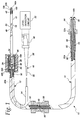
- FIG. 1 illustrates a fluid sensing pipette 10 including a distal pipette section 12, a proximal pipette section 14, and a twisted wire section 16.
- the distal pipette section 12 includes an outer conductive tube 18 and an inner conductive tube 20 concentrically disposed within the outer conductive tube 18.
- the outer tube 18 extends along the distal pipette section 12 from a proximal location 18a to a distal location 18b.
- the inner tube 20 extends from a proximal location 20a to a distal location 20b.
- the outer tube 18 is preferably composed of electro-polished stainless steel, and the inner tube is composed of stainless steel.
- the outer tube 18 is insulated from the inner tube 20 by a uniform, consistent, and conformal polymeric coating 19 applied to the outer surface of the inner tube 20. Furthermore, the outer tube 18 is bonded over the inner tube 20 by a water resistant and electrically insulating epoxy. This epoxy prevents fluid from entering the region between the outer and inner tubes 18, 20 at the distal end 18b of the outer tube 18.
- the polymeric coating 19 is composed of a member of the Parylene polymer series (e.g., Parylene N, C, or D) manufactured by Union Carbide Corporation.
- the basic member of the series, Parylene N is poly (para-xylylene).
- Parylene C is poly (2-chloro-para-xylylene), and
- Parylene D is poly (2,5-dichloro-para-xylylene).
- the Selected Parylene polymer is vacuum deposited over substantially all of the outer surface of the inner tube 20 to form a conformal, thin, continuous, uniform adherent coating having a thickness of about 0.001".
- the polymeric coating 19 extends from the proximal end 20a of the inner conductive tube 20 to a distal location 19b spaced a relatively short longitudinal distance away from the distal end 20b of the inner conductive tube 20.
- the polymeric coating 19 provides a hydrophobic surface for preventing liquid from collecting on the outer surface of the inner conductive tube 20 between the distal end 18b of the outer tube 18 and the distal end 19b of the polymeric coating 19.
- the polymeric coating 19 does not extend entirely to the distal end 20b so that a portion of the inner tube 20 remains exposed for impedance measurements when the pipette 10 is immersed in a liquid.
- the conductive tubes 18, 20 each serve as one electrode of a level detection circuit 22 connected to the proximal end of the twisted pair section 16.
- the conductive tubes 18, 20 are coupled to the level detection circuit 22 by means of respective uninsulated wire connectors 24, 26 and respective insulated wires 28, 30.
- the wire connectors 24, 26 are preferably composed of fairly rigid, nickel-plated copper wire.
- One end of the wire connector 24 is wound about and soldered to the outer conductive tube 18, while the other end is connected to the insulated wire 28.
- one end of the wire connector 26 is wound about and soldered to the inner conductive tube 20, while the other end is connected to the insulated wire 30.
- an ABS machined housing 44 contains an epoxy potting compound 46 for protecting these connections.
- the housing 44 is also used to mount the pipette 10 onto an automated analyzer.
- the wires 28, 30 form a conventional twisted wire pair extending through a plastic jacket 32 to a wire termination connector 40.
- the wires 28, 30 are connected to the termination connector 40 by means of crimping.
- the jacket 32 is reinforced with a plastic sleeve 34 shrink-wrapped about the jacket 32.
- another plastic sleeve 38 is shrink-wrapped about the jacket 32 at a location adjacent the termination connector 40. The shrink-wrapped plastic sleeves 34, 38 prevent damage from being incurred to the twisted pair of wires 28, 30 at those locations where the wires are more susceptible to damage.
- the termination connector 40 is designed such that the wires 28, 30 must be separated from one another when crimped thereto. Therefore, it can be seen in FIG. 1 that the cross-sectional area of the sleeve 38 increases in the direction of the termination connector 40.
- the wire termination connector 40 is employed to connect the pipette 10 to the level detection circuit 22.
- the pipette 10 is provided with a polymeric inner tube 48, preferably composed of TEFLON, for containing fluids which pass through the pipette 10.
- TEFLON is a trademark for tetrafluoroethylene (TFE) fluorocarbon polymers and is available from E.I. Du Pont de Nemours Co. of Wilmington, Delaware.
- TFE tetrafluoroethylene
- the polymeric tube 48 is concentrically disposed within the inner conductive tube 20.
- the polymeric tube 48 extends entirely through the distal and proximal pipette sections 12, 14, forming a nozzle 48a at one end and a flared portion 48b at the other end.
- the polymeric tube 48 is hydrophobic, fluid is repelled from the inner surface of the tube 48. Therefore, after the pipette 10 operates on a biological sample and the pipette 10 is cleansed with cleaning solution, no portion of that biological sample remains adhered to the inner surface of the tube 48. As a result, there is no cross-contamination between different biological samples.
- the tube 48 is threaded through a KYNAR sleeve 50, where KYNAR is the trademark of the Pennsalt Co. for the generic material polyvinylidene fluoride.
- the KYNAR sleeve 50 extends from a proximal location 50a to a distal location 50b within the housing 44.
- a spiral wrap 52 is disposed about the KYNAR sleeve 50. The spiral wrap 52 extends from a proximal location 52a within a pipette connector 54 to a distal location 52b within the housing 44.
- the jacket 32 containing the wires 28, 30 is disposed between the KYNAR sleeve 50 and the spiral wrap 52.
- the reinforcing sleeve 34 prevents damage to the jacket 32 or the wires 28, 30 at the point where the jacket 32 is separated from the spiral wrap 52.
- an anti-kink spring 53 is disposed concentrically about the tube 48 and within the spiral wrap 52.
- the spring 53 is longitudinally positioned between the proximal end 50a of the KYNAR sleeve 50 and the pipette connector 54.
- the pipette 10 is further provided with a locator block 59, rigidly mounted within the automated analyzer, to prevent movement of the proximal pipette section 14 while the automated analyzer maneuvers the distal pipette section 12.
- the pipette connector 54 is engaged with a mating connector (not shown) which, in turn, is connected to a two-way, three-port valve 60 (FIG. 2).
- the valve 60 is then coupled to both a source of cleaning solution 62 and a syringe pump 64 (FIG. 2).
- the flared portion 48b of the polymeric tube 48 extends about a rubber O-ring 56 positioned between the pipette connector 54 and the mating connector.
- the rubber O-ring 56 cooperates with the flared portion 48b to prevent fluid leakage as cleaning solution passes from the source of cleaning solution and into the pipette 10.
- the pipette 10 is cleansed by switching the two-way valve 60 so as to permit cleaning solution 62 to be pumped by the syringe pump 64 into the pipette 10 via the connector 54.
- the cleaning solution is passed through the plastic tube 48 and expelled from the nozzle 48a thereof into a cylindrical well 66 within a discharge basin 68.
- the well 66 is constructed so that after the expelled cleaning solution strikes the bottom of the well 66, the expelled cleaning solution is forced back up around the outer surface of the pipette 10 between the inner surface of the well 66 and this outer surface of the pipette 10.
- the expelled cleaning solution then overflows out the top of the well 66 and is directed by the discharge basin 68 to a waste tank (not shown).
- the distal outer surface of the pipette 10 is cleansed by the action of the cleaning solution being forced back up around the outer surface of the pipette 10 between the inner surface of the well 66 and the outer surface of the pipette 10.
- the well 66 is sufficiently deep to cleanse the outer surface of the nozzle 48a and the distal outer surfaces of the inner conductive tube 20 and outer conductive tube 18.
- the amount of time required to cleanse the outer surface of the pipette 10 is dependent upon the surface area of that outer surface which must be cleansed. The larger the surface area of the outer surface, the longer the time required to cleanse that outer surface. Since it is advantageous to minimize the required time for cleansing the outer surface of the pipette 10, it is preferable to minimize the surface area of the outer surface by minimizing the outer diameter of the pipette 10.
- the outer diameter of the pipette 10 is minimized by employing the thin, uniform, and consistent polymeric coating 19 over the inner conductive tube 20, as opposed to separate and much thicker plastic sleeve between the outer and inner conductive tubes 18, 20.
- the outer conductive tube 18 has an outer diameter of approximately 0.083 inches and an inner diameter of approximately 0.077 inches;
- the inner conductive tube 20 has an outer diameter of approximately 0.072 inches and an inner diameter of approximately 0.064 inches;
- the polymeric coating 19 over the inner conductive tube 20 has a thickness of approximately 0.001 inches.
- the polymeric tube 48 prior to being threaded through the inner conductive tube 20, has an outer diameter of approximately 0.070 inches and an inner diameter of 0.050 inches.
- the polymeric tube 48 is first stretched to temporarily provide the tube 48 with a smaller outer diameter and permit the tube 48 to be inserted into the inner conductive tube 20. Due to memory retention, the polymeric tube 48 expands within the inner conductive tube 20 to firmly secure the polymeric tube 48 within the inner conductive tube 20.
- the pipette 10 is designed to detect entry of the distal tip of the pipette 10 ink a sample within a test tube.
- This fluid sensing feature is accomplished by the outer and inner conductive tubes 18, 20, in conjunction with the level detection circuit 22.
- the outer conductive tube 18 forms a first electrode which is coupled to the level detection circuit 22 using the wire connector 24 and the wire 28.
- the inner conductive tube 20 forms a second electrode which is coupled to the level detection circuit 22 using the wire connector 26 and the wire 30.
- the level detection circuit 22 senses a decrease in impedance between the first and second electrodes. If the impedance between the electrodes falls below a predetermined threshold, then the circuit 22 detects entry of the pipette tip into the sample.
- this detection by the circuit 22 is used to signal a motor to stop the downward motion of the pipette 10 into the sample.
- the pipette 10 then aspirates a certain desired volume of sample and automatically dispenses the aspirated volume over multiple reagent pads. After dispensing the aspirated sample, the pipette tip enters the well 66 (FIG. 2) where it is thoroughly cleansed of the sample in the manner previously described.
- FIG. 3 is a schematic diagram of the level detection circuit 22, which is connected to the pipette 10 using the termination connector 40.
- the illustrated circuit 22 employs an LM1830N fluid detector 70 manufactured by National Semiconductor Corporation.
- the fluid detector 70 is a monolithic bipolar integrated circuit designed for use in fluid detection systems.
- the integrated circuit 70 internally contains both an oscillator and voltage detector, and the circuit 70 includes a plurality of terminals 72-77.
- an external capacitor C1 is connected between the terminals 72 and 73 of the integrated circuit 70. This produces an oscillating output signal at the terminal 74 of the integrated circuit 70.
- the frequency of oscillation of the oscillating output signal is inversely proportional to the value of the external capacitor C1.
- the capacitor C1 has a value 0.001 microfarads so that the output frequency is approximately 8 kilohertz.
- the oscillating output signal at the terminal 74 of the integrated circuit 70 is coupled through a resistor R1 and a ceramic capacitor C2 to the voltage detector input at the terminal 75 of the integrated circuit 70.
- the resistor R1 has a value of 20 kiloohms
- the capacitor C2 has a value of 0.1 microfarads. These values cause the level detector circuit 22 to have an impedance threshold of approximately 16 kiloohms, below which the circuit 22 detects fluid and above which the circuit 22 does not detect fluid.
- the detector input terminal 75 is also connected to the wire 30 which, in turn, is connected to the inner conductive tube 20 of the pipette 10.
- the outer conductive tube 18 is grounded by connecting the wire 28 to ground.
- Power is supplied to the integrated circuit 70 by connecting a +12 volt DC source (“Vcc”) to the power supply terminal 77, and a terminal 78 of the integrated circuit 70 is connected to ground.
- the output terminal 76 is coupled through a 1.2 kiloohm resistor R2 to the voltage source Vcc.
- the output terminal 76 is coupled through a light-emitting diode (LED) 80 to the base of a transistor Q, which preferably is a 2N4124 transistor manufactured by National Semiconductor Corporation.
- the transistor emitter is connected to ground, and the transistor base is coupled through a 100 ohm resistor R3 to ground.
- the transistor collector is coupled through a 3.3 kiloohm resistor R4 to the power source Vcc.
- the time constant determined by the resistor R2 and the capacitor C3 determine the response time of the level detection circuit 22.
- the LED 80 and the transistor Q do not conduct until the output terminal 76 ceases to conduct and the capacitor C3 charges through the resistor R2.
- the level detection circuit 22 determines the presence or absence of fluid by comparing the impedance between the outer and inner conductive tubes 18, 20 with the preset threshold impedance of 16 kiloohms.
- the oscillator output signal from the terminal 74 is coupled to the detector input terminal 75 so as to turn on an internal transistor located within the integrated circuit 70 and coupled to the output terminal 76.
- the LED 80 is "Off"
- the transistor Q is nonconducting
- the transistor output along a line 82 is logic HI.
- the output terminal 76 of the integrated circuit is nonconducting.
- a sufficient amount of current passes through the LED 80 to turn “On” the LED 80.
- the transistor Q is conducting and the transistor output along the line 82 is logic LOW.
- Fluids with low ionic content have a higher impedance than fluids with a higher ionic content.
- the threshold impedance of the level detection circuit 22 is 16 kiloohms, the pipette 10 is sensitive to a variety of higher ionic fluids (e.g., urine samples) and is nonresponsive to lower ionic fluids and de-ionized fluids.
- the level detection circuit 22 allows the depth of immersion of the pipette 10 into a higher ionic fluid sample to be carefully controlled such that the pipette 10 is submerged into the sample just deep enough to aspirate the sample without drawing up any air.
- This controlled depth of immersion causes the sample to contact only a very small fraction of the pipette 10, thereby minimizing the amount of the pipette 10 which must be cleansed in each sampling cycle.
- the cleaning solution used to cleanse the pipette 10 has a sufficiently low ionic content that the level detection circuit 22 does not mistake the cleaning solution for the sample.
Applications Claiming Priority (2)
| Application Number | Priority Date | Filing Date | Title |
|---|---|---|---|
| US20067594A | 1994-02-23 | 1994-02-23 | |
| US200675 | 1994-02-23 |
Publications (1)
| Publication Number | Publication Date |
|---|---|
| EP0670497A1 true EP0670497A1 (fr) | 1995-09-06 |
Family
ID=22742697
Family Applications (1)
| Application Number | Title | Priority Date | Filing Date |
|---|---|---|---|
| EP95101832A Withdrawn EP0670497A1 (fr) | 1994-02-23 | 1995-02-10 | Pipette avec détection de niveau de fluide |
Country Status (5)
| Country | Link |
|---|---|
| US (1) | US5550059A (fr) |
| EP (1) | EP0670497A1 (fr) |
| JP (1) | JPH07270215A (fr) |
| AU (1) | AU665158B2 (fr) |
| CA (1) | CA2140996A1 (fr) |
Cited By (5)
| Publication number | Priority date | Publication date | Assignee | Title |
|---|---|---|---|---|
| WO1997044133A1 (fr) * | 1996-05-23 | 1997-11-27 | Möller Feinmechanik GmbH & Co. KG | Dispositif de prelevement d'echantillon pour liquides |
| EP0819942A2 (fr) * | 1996-07-19 | 1998-01-21 | Hitachi, Ltd. | Dispositif pour le transfert de liquides avec mesure de niveau de liquide |
| DE19750642A1 (de) * | 1996-11-19 | 1998-05-28 | Hitachi Ltd | Analysator mit Flüssigkeitspegeldetektor |
| EP1632757A1 (fr) * | 2004-09-06 | 2006-03-08 | Tecan Trading AG | Elément en forme de barre pour détecter un niveau de liquide et un dispositif correspondant pour la détection d'un niveau de liquide |
| WO2008005440A2 (fr) * | 2006-06-30 | 2008-01-10 | University Of Illinois | surveillance et contrôle de l'hydrocéphalie |
Families Citing this family (36)
| Publication number | Priority date | Publication date | Assignee | Title |
|---|---|---|---|---|
| US6270726B1 (en) * | 1999-09-30 | 2001-08-07 | Dpc Cirrus, Inc. | Tube bottom sensing for small fluid samples |
| DE10004941A1 (de) * | 2000-02-06 | 2001-08-09 | Reimer Offen | Temperierter Probennehmer für Flüssigkeiten |
| EP2230521A3 (fr) | 2000-02-29 | 2013-11-13 | Gen-Probe Incorporated | Système de distribution de fluide et de vérification d'une surface de liquide et méthode correspondante |
| US6296452B1 (en) | 2000-04-28 | 2001-10-02 | Agilent Technologies, Inc. | Microfluidic pumping |
| DE10052819B4 (de) * | 2000-10-24 | 2004-02-19 | Fraunhofer-Gesellschaft zur Förderung der angewandten Forschung e.V. | Pipettensystem und Pipettenarray sowie Verfahren zum Befüllen eines Pipettensystems |
| WO2002059626A1 (fr) * | 2001-01-25 | 2002-08-01 | Tecan Trading Ag | Dispositif de pipettage |
| CN101002100B (zh) * | 2004-07-12 | 2011-06-08 | Vdg-冯德尔戈尔茨有限责任公司 | 用于自动检验血样的装置和方法 |
| US7360461B2 (en) * | 2004-09-23 | 2008-04-22 | Aircuity, Inc. | Air monitoring system having tubing with an electrically conductive inner surface for transporting air samples |
| US20070286770A1 (en) * | 2006-03-13 | 2007-12-13 | Sage Science, Inc. | Laboratory Reagent and Sample Assembly, Management and Processing |
| US20080031774A1 (en) * | 2006-03-13 | 2008-02-07 | Sage Science, Inc. | Apparatus for Guiding Sample and Reagent Manipulations and Receptacles for Holding Same |
| US7621181B2 (en) * | 2006-04-12 | 2009-11-24 | Siemens Healthcare Diagnostics Inc. | Fluid level detector and analyzer |
| US7549349B2 (en) * | 2006-06-22 | 2009-06-23 | Evogen, Inc. | Sample cartridge for air-sampling device |
| US7794664B2 (en) | 2006-11-16 | 2010-09-14 | Idexx Laboratories, Inc. | Pipette tip |
| US8703492B2 (en) | 2007-04-06 | 2014-04-22 | Qiagen Gaithersburg, Inc. | Open platform hybrid manual-automated sample processing system |
| US7985375B2 (en) * | 2007-04-06 | 2011-07-26 | Qiagen Gaithersburg, Inc. | Sample preparation system and method for processing clinical specimens |
| WO2009023448A1 (fr) | 2007-08-13 | 2009-02-19 | Polyone Corporation | Mélanges de polyoléfines électriquement conducteurs |
| JP4538477B2 (ja) * | 2007-08-31 | 2010-09-08 | 株式会社日立ハイテクノロジーズ | 自動分析装置 |
| US7921549B2 (en) * | 2007-09-10 | 2011-04-12 | John Mezzalingua Associates, Inc. | Tool and method for connecting a connector to a coaxial cable |
| US8516696B2 (en) | 2007-09-10 | 2013-08-27 | John Mezzalingua Associates, LLC | Hydraulic compression tool for installing a coaxial cable connector and method of operating thereof |
| US8661656B2 (en) | 2007-09-10 | 2014-03-04 | John Mezzallingua Associates, LLC | Hydraulic compression tool for installing a coaxial cable connector and method of operating thereof |
| US8595928B2 (en) | 2007-09-10 | 2013-12-03 | John Mezzalingua Associates, LLC | Method for installing a coaxial cable connector onto a cable |
| US10819077B2 (en) | 2007-09-10 | 2020-10-27 | John Mezzalingua Associates, LLC | Compression tool with biasing member |
| WO2009061748A1 (fr) * | 2007-11-07 | 2009-05-14 | Siemens Heathcare Diagnostics Inc. | Système d'aspiration d'une trombe |
| JP2009281877A (ja) * | 2008-05-22 | 2009-12-03 | Hitachi High-Technologies Corp | 分注装置 |
| US9953141B2 (en) | 2009-11-18 | 2018-04-24 | Becton, Dickinson And Company | Laboratory central control unit method and system |
| EP2726884B1 (fr) | 2011-07-01 | 2020-02-05 | Beckman Coulter, Inc. | Sonde de manipulation de liquide à faible report pour analyseur automatisé |
| US10240182B2 (en) * | 2013-08-25 | 2019-03-26 | Lishtot Detection, Ltd. | Devices and methods for identifying a biological or chemical residue in an aqueous sample |
| US20150362420A1 (en) * | 2014-06-13 | 2015-12-17 | Wafergen, Inc. | Systems for single or multiple cell counting and dispensing |
| CN104297039B (zh) * | 2014-09-25 | 2017-01-11 | 深圳市奥特库贝科技有限公司 | 一种新型磁分离机构 |
| WO2016122565A1 (fr) * | 2015-01-30 | 2016-08-04 | Hewlett-Packard Development Company, L.P. | Détection microfluidique |
| CN106950390A (zh) * | 2017-04-20 | 2017-07-14 | 合肥迪安医学检验所有限公司 | 生化仪血液样本自动加样探测头 |
| EP3501654B1 (fr) * | 2017-12-22 | 2021-08-25 | Tecan Trading Ag | Appareil de pipetage avec un tube de pipette et procédé pour détecter un liquide à l'intérieur d'une section intermédiaire du tube de pipette |
| CN116651529A (zh) | 2017-12-28 | 2023-08-29 | 富默乐有限公司 | 用于自动地保持流体中的吸移管吸头深度的吸移管吸头和方法 |
| JP6837086B2 (ja) * | 2019-01-24 | 2021-03-03 | 日本電子株式会社 | 自動分析装置 |
| US11473699B2 (en) | 2020-06-26 | 2022-10-18 | Biolytic Lab Performance, Inc | Tubing support system |
| CN116324422A (zh) | 2020-10-07 | 2023-06-23 | 美国西门子医学诊断股份有限公司 | 多点滤波液体液位检测方法和装置 |
Citations (6)
| Publication number | Priority date | Publication date | Assignee | Title |
|---|---|---|---|---|
| US3754444A (en) * | 1970-09-14 | 1973-08-28 | Bio Logics Products | Medical sampling and reading |
| EP0070571A2 (fr) * | 1981-07-21 | 1983-01-26 | BAXTER INTERNATIONAL INC. (a Delaware corporation) | Commande pour distributeur de liquide automatisé |
| US4704088A (en) * | 1984-04-27 | 1987-11-03 | Newman Martin H | Dental materials dispenser and applicator |
| GB2216656A (en) * | 1988-03-23 | 1989-10-11 | Olympus Optical Co | Measuring hematocrit valve and sampling plasma and blood cells |
| WO1992022379A1 (fr) * | 1991-06-13 | 1992-12-23 | Applied Research Systems Ars Holding N.V. | Sonde de prelevement par pipette comprenant un entrainement reduit du reactif |
| EP0555710A2 (fr) * | 1992-02-08 | 1993-08-18 | Roche Diagnostics GmbH | Dispositif de transfert de liquide pour appareil d'analyse |
Family Cites Families (14)
| Publication number | Priority date | Publication date | Assignee | Title |
|---|---|---|---|---|
| US3391547A (en) * | 1966-02-28 | 1968-07-09 | Varian Associates | Capacitive liquid level sensor using phase sensitive detector means |
| GB1287148A (en) * | 1969-06-11 | 1972-08-31 | Thomas Electronics Ltd | Improvements in or relating to water level detectors |
| DE2041678A1 (de) * | 1969-09-06 | 1971-03-11 | Greiner Electronic Ag | Verfahren zum Betrieb einer Transferpipette |
| US4389900A (en) * | 1979-06-14 | 1983-06-28 | The United States Of America As Represented By The Secretary Of The Interior | Capacitance probe sensor device |
| US4276258A (en) * | 1980-01-28 | 1981-06-30 | Coulter Electronics, Inc. | Sample and stat feeding system and sample tray |
| US4276260A (en) * | 1980-01-28 | 1981-06-30 | Coulter Electronics, Inc. | Fluid transfer mechanism |
| DE3009205A1 (de) * | 1980-03-11 | 1981-09-24 | Robert Bosch Gmbh, 7000 Stuttgart | Aktives nf-bandpassfilter |
| US4326851A (en) * | 1980-10-24 | 1982-04-27 | Coulter Electronics, Inc. | Level sensor apparatus and method |
| JPS5822946A (ja) * | 1981-08-03 | 1983-02-10 | Olympus Optical Co Ltd | 境界面検出装置 |
| US4577514A (en) * | 1984-04-09 | 1986-03-25 | Vanderbilt University | Method and apparatus for sampling liquid phase components from a liquid-semisolid fluid |
| CA1268814A (fr) * | 1984-06-13 | 1990-05-08 | Larry Wayne Moore | Dispositifs et methodes de sondage d'un niveau de fluide |
| US4736638A (en) * | 1985-12-20 | 1988-04-12 | Beckman Instruments, Inc. | Liquid level sensor |
| JPH0833320B2 (ja) * | 1986-03-20 | 1996-03-29 | 株式会社東芝 | 自動化学分析装置 |
| US5045286A (en) * | 1988-02-25 | 1991-09-03 | Olympus Optical Co., Ltd. | Device for aspirating a fixed quantity of liquid |
-
1994
- 1994-12-16 US US08/358,111 patent/US5550059A/en not_active Expired - Lifetime
-
1995
- 1995-01-24 CA CA002140996A patent/CA2140996A1/fr not_active Abandoned
- 1995-02-10 EP EP95101832A patent/EP0670497A1/fr not_active Withdrawn
- 1995-02-20 JP JP7030705A patent/JPH07270215A/ja active Pending
- 1995-02-22 AU AU13442/95A patent/AU665158B2/en not_active Ceased
Patent Citations (6)
| Publication number | Priority date | Publication date | Assignee | Title |
|---|---|---|---|---|
| US3754444A (en) * | 1970-09-14 | 1973-08-28 | Bio Logics Products | Medical sampling and reading |
| EP0070571A2 (fr) * | 1981-07-21 | 1983-01-26 | BAXTER INTERNATIONAL INC. (a Delaware corporation) | Commande pour distributeur de liquide automatisé |
| US4704088A (en) * | 1984-04-27 | 1987-11-03 | Newman Martin H | Dental materials dispenser and applicator |
| GB2216656A (en) * | 1988-03-23 | 1989-10-11 | Olympus Optical Co | Measuring hematocrit valve and sampling plasma and blood cells |
| WO1992022379A1 (fr) * | 1991-06-13 | 1992-12-23 | Applied Research Systems Ars Holding N.V. | Sonde de prelevement par pipette comprenant un entrainement reduit du reactif |
| EP0555710A2 (fr) * | 1992-02-08 | 1993-08-18 | Roche Diagnostics GmbH | Dispositif de transfert de liquide pour appareil d'analyse |
Cited By (11)
| Publication number | Priority date | Publication date | Assignee | Title |
|---|---|---|---|---|
| WO1997044133A1 (fr) * | 1996-05-23 | 1997-11-27 | Möller Feinmechanik GmbH & Co. KG | Dispositif de prelevement d'echantillon pour liquides |
| EP0819942A2 (fr) * | 1996-07-19 | 1998-01-21 | Hitachi, Ltd. | Dispositif pour le transfert de liquides avec mesure de niveau de liquide |
| EP0819942A3 (fr) * | 1996-07-19 | 1998-09-23 | Hitachi, Ltd. | Dispositif pour le transfert de liquides avec mesure de niveau de liquide |
| DE19750642A1 (de) * | 1996-11-19 | 1998-05-28 | Hitachi Ltd | Analysator mit Flüssigkeitspegeldetektor |
| DE19750642C2 (de) * | 1996-11-19 | 1998-11-26 | Hitachi Ltd | Analysator mit Pipettiersonde |
| US6107810A (en) * | 1996-11-19 | 2000-08-22 | Hitachi, Ltd. | Analyzer with function of detecting liquid level |
| EP1632757A1 (fr) * | 2004-09-06 | 2006-03-08 | Tecan Trading AG | Elément en forme de barre pour détecter un niveau de liquide et un dispositif correspondant pour la détection d'un niveau de liquide |
| US7207219B2 (en) | 2004-09-06 | 2007-04-24 | Tecan Trading Ag | Rod-shaped element for liquid level detection and corresponding device for liquid level detection |
| WO2008005440A2 (fr) * | 2006-06-30 | 2008-01-10 | University Of Illinois | surveillance et contrôle de l'hydrocéphalie |
| WO2008005440A3 (fr) * | 2006-06-30 | 2008-04-10 | Univ Illinois | surveillance et contrôle de l'hydrocéphalie |
| US8457733B2 (en) | 2006-06-30 | 2013-06-04 | Andreas Linninger | Monitoring and controlling hydrocephalus |
Also Published As
| Publication number | Publication date |
|---|---|
| AU665158B2 (en) | 1995-12-14 |
| CA2140996A1 (fr) | 1995-08-24 |
| JPH07270215A (ja) | 1995-10-20 |
| US5550059A (en) | 1996-08-27 |
| AU1344295A (en) | 1995-09-07 |
Similar Documents
| Publication | Publication Date | Title |
|---|---|---|
| AU665158B2 (en) | Fluid sensing pipette | |
| EP1261876B1 (fr) | Systeme permettant de verifier la surface d'un fluide et de la distribution d'un fluide | |
| AU2001245365A1 (en) | Fluid dispense and liquid surface verification system and method | |
| CN109414698B (zh) | 具有液体体积传感器和液体处理系统的移液设备 | |
| JPH0833320B2 (ja) | 自動化学分析装置 | |
| US6021253A (en) | Heating probe | |
| US5843378A (en) | Method of producing a probe for aspirating and dispensing probe having surface sensing capability | |
| CN111565848A (zh) | 带有移液管的移液装置和用于检测在移液管的中间段内的液体的方法 | |
| JPH10132640A (ja) | 液面検出装置及び液面検出方法、並びに自動分析装置 | |
| AU606935B2 (en) | Liquid level sensing device | |
| AU2005211566B2 (en) | Fluid dispense and fluid surface verification system and method | |
| US7207219B2 (en) | Rod-shaped element for liquid level detection and corresponding device for liquid level detection | |
| JPH01216268A (ja) | 液体分注装置 | |
| RU1835508C (ru) | Датчик дл измерени величины рН | |
| JPH073297Y2 (ja) | 液面センサを備えた吸排ノズル |
Legal Events
| Date | Code | Title | Description |
|---|---|---|---|
| PUAI | Public reference made under article 153(3) epc to a published international application that has entered the european phase |
Free format text: ORIGINAL CODE: 0009012 |
|
| AK | Designated contracting states |
Kind code of ref document: A1 Designated state(s): AT BE CH DE DK ES FR GB GR IE IT LI LU NL PT SE |
|
| 17P | Request for examination filed |
Effective date: 19960214 |
|
| RAP1 | Party data changed (applicant data changed or rights of an application transferred) |
Owner name: BAYER CORPORATION |
|
| STAA | Information on the status of an ep patent application or granted ep patent |
Free format text: STATUS: THE APPLICATION HAS BEEN WITHDRAWN |
|
| 18W | Application withdrawn |
Withdrawal date: 19980126 |