EP0670433B1 - Universal joint having exterior lubricating ring - Google Patents
Universal joint having exterior lubricating ring Download PDFInfo
- Publication number
- EP0670433B1 EP0670433B1 EP95101250A EP95101250A EP0670433B1 EP 0670433 B1 EP0670433 B1 EP 0670433B1 EP 95101250 A EP95101250 A EP 95101250A EP 95101250 A EP95101250 A EP 95101250A EP 0670433 B1 EP0670433 B1 EP 0670433B1
- Authority
- EP
- European Patent Office
- Prior art keywords
- ring
- lubricant
- shaft
- yoke
- universal joint
- Prior art date
- Legal status (The legal status is an assumption and is not a legal conclusion. Google has not performed a legal analysis and makes no representation as to the accuracy of the status listed.)
- Expired - Lifetime
Links
Images


Classifications
-
- F—MECHANICAL ENGINEERING; LIGHTING; HEATING; WEAPONS; BLASTING
- F16—ENGINEERING ELEMENTS AND UNITS; GENERAL MEASURES FOR PRODUCING AND MAINTAINING EFFECTIVE FUNCTIONING OF MACHINES OR INSTALLATIONS; THERMAL INSULATION IN GENERAL
- F16D—COUPLINGS FOR TRANSMITTING ROTATION; CLUTCHES; BRAKES
- F16D3/00—Yielding couplings, i.e. with means permitting movement between the connected parts during the drive
- F16D3/16—Universal joints in which flexibility is produced by means of pivots or sliding or rolling connecting parts
- F16D3/26—Hooke's joints or other joints with an equivalent intermediate member to which each coupling part is pivotally or slidably connected
- F16D3/38—Hooke's joints or other joints with an equivalent intermediate member to which each coupling part is pivotally or slidably connected with a single intermediate member with trunnions or bearings arranged on two axes perpendicular to one another
- F16D3/42—Hooke's joints or other joints with an equivalent intermediate member to which each coupling part is pivotally or slidably connected with a single intermediate member with trunnions or bearings arranged on two axes perpendicular to one another with ring-shaped intermediate member provided with bearings or inwardly-directed trunnions
-
- F—MECHANICAL ENGINEERING; LIGHTING; HEATING; WEAPONS; BLASTING
- F16—ENGINEERING ELEMENTS AND UNITS; GENERAL MEASURES FOR PRODUCING AND MAINTAINING EFFECTIVE FUNCTIONING OF MACHINES OR INSTALLATIONS; THERMAL INSULATION IN GENERAL
- F16D—COUPLINGS FOR TRANSMITTING ROTATION; CLUTCHES; BRAKES
- F16D3/00—Yielding couplings, i.e. with means permitting movement between the connected parts during the drive
- F16D3/16—Universal joints in which flexibility is produced by means of pivots or sliding or rolling connecting parts
- F16D3/26—Hooke's joints or other joints with an equivalent intermediate member to which each coupling part is pivotally or slidably connected
- F16D3/30—Hooke's joints or other joints with an equivalent intermediate member to which each coupling part is pivotally or slidably connected in which the coupling is specially adapted to constant velocity-ratio
- F16D3/32—Hooke's joints or other joints with an equivalent intermediate member to which each coupling part is pivotally or slidably connected in which the coupling is specially adapted to constant velocity-ratio by the provision of two intermediate members each having two relatively perpendicular trunnions or bearings
- F16D3/33—Hooke's joints or other joints with an equivalent intermediate member to which each coupling part is pivotally or slidably connected in which the coupling is specially adapted to constant velocity-ratio by the provision of two intermediate members each having two relatively perpendicular trunnions or bearings with ball or roller bearings
Definitions
- the present invention relates to universal joints.
- Universal joints are used in a multitude of industries, including the aerospace, automotive and marine industries.
- the aerospace industry uses universal joints, for example, to transfer power to control surfaces.
- Universal joints are used in steering columns in automobiles to transfer power.
- Universal joints are used in boat motors.
- universal joints can be found in everything from tractors to robots.
- a universal joint comprising a ring containing a lubricant passage having lubricant ports, a first and a second shaft, a yoke connected to the second shaft and disposed within the ring, first pin means pivotally interconnecting the yoke and the ring, further pin means pivotally interconnecting the first shaft and the ring, and a plurality of bearing means in the ring in fluid contact with the lubricant passage and receiving the first and further pin means, characterised in that the lubricant passage is a single channel which is in the ring and extends less than 360 degrees around the ring between two end regions of the passage, the end regions having respective lubricant ports which open into the passage at respective, spaced, portions so that lubricant entering one lubricant port must travel through substantially the entire length of the lubricant passage before exiting through the second lubricant port.
- the present invention can provide a universal joint especially designed for high operating angle and high r.p.m. applications.
- a first embodiment of the joint comprises a ball, a hemispherical split-cup shaped yoke and a ring, the ball being inside the yoke, which is inside the ring; pins connect the ring to the yoke and to the ball.
- a first shaft is connected to the ball and a second shaft is connected to the yoke.
- the yoke is cup-shaped internally to have the closest fit to the ball.
- the yoke is cup-shaped externally to have the closest fit to the ring.
- the cup shape of the yoke enables it to withstand centrifugal and torsional loads better than conventional Y-shaped yokes.
- the ring, the shaft, the ball and the yoke are each formed from components which are circularly symmetrical about their own longitudinal axes. This shape of the components allows the joint to be manufactured in computerized lathes and allows the joint to run at higher angles and at higher r.p.m. with less vibration than other universal joints.
- a second, preferred, embodiment of the present invention is a universal joint comprising a cross trunnion, a hemispherical split-cup shaped yoke and a ring, the cross trunnion being inside the yoke, which is inside the ring; pins connect the ring to the yoke and to the cross trunnion.
- a first shaft is connected to the cross trunnion and a second shaft is connected to the yoke.
- the yoke is shaped internally to have a close fit to the cross trunnion while allowing the cross trunnion to freely move therein at the desired operating angle of the joint without contact of the two parts.
- the yoke is cup-shaped externally to have the closest fit to the ring while allowing the ring to oscillate therearound without contact of the two parts.
- the cup shape of the yoke enables it to withstand centrifugal and torsional loads better than conventional Y-shaped yokes.
- the ring and the yoke are each formed from components which are circularly symmetrical about their own longitudinal axes. This shape of the components allows the joint to be manufactured in computerized lathes which facilitates balancing and allows the joint to run at higher angles and at higher r.p.m. with less vibration than other universal joints.
- the ball or cross trunnion inside the yoke with the yoke inside the ring causes the bulk of the mass of the universal joint to be closer to the spin axis of the universal joint than would be possible if the ring were between the cross trunnion and the yoke. This reduces the effects of centrifugal force, allowing for greater dynamic joint stability.
- the yoke may be bevelled internally to minimize its size and maximize its strength, while maximizing the operating angle of the joint.
- Having the ball or cross trunnion inside the yoke enables the joint to be misaligned at angles up to and beyond 45° in less lateral distance (that is, distance along the longitudinal axis of the joint) than in conventional Cardan-type joints.
- lubrication of the pins and bearings is also achieved by means of the non-continuous lubricant-filled channel in the ring.
- Lubricant ports are provided to allow the channel to be filled with lubricant.
- Bearing assemblies having two lubricant ports located in the outer race and 180° apart are in communication with the annular lubricant channel in the ring allowing the lubricant to be pumped through the ring and through all four bearing assemblies.
- the two adjacent lubricant ports in the ring are only connected by the non-continuous annular channel with there being no communication in the shortest distance between the two ports in the ring.
- the joints are designed to accommodate an operating angle of up to 45° between the drive shaft and the driven shaft.
- Fig. 1 is an exploded view of a universal joint in accordance with EP-0493388.
- Fig. 2 is a side view of the embodiment of the joint shown in Fig. 1.
- Fig. 3 is a sectional view of an alternative embodiment of EP-0493388.
- Fig. 4 is a sectional view of the pivot ring of the first and second embodiments of EP-0493388.
- Fig. 5 is a sectional view taken along the lines 5-5 in Fig. 6.
- Fig. 6 is a partially cut-away view of a third embodiment of EP-0493388.
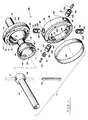
- Fig. 7 is an exploded view of the preferred embodiment of the universal joint of the present invention.
- Fig. 8 is a side view of the preferred embodiment of the present invention.
- Fig. 9 is a sectional view of the preferred embodiment of the present invention.
- Fig. 10 is a sectional view of the pivot ring of the preferred embodiment of the present invention.
- Fig. 11 is a sectional view taken along the lines 11-11 in Fig. 12.
- Fig. 12 is a partially cut-away view of a fifth embodiment of the universal joint of the present invention.
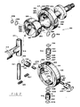
- universal joint 10 (Figs. 5 and 6), comprises a hemispherical split-cup yoke 11, a ball 12, a shaft 13, a shaft 14, and a ring 15.
- Yoke 11 has a substantially hemispherical outer surface and a concentric, substantially hemispherical inner surface.
- a relatively long pin 21 extends through a hole 41 (see Fig. 1) in ball 12 into ring 15.
- Relatively short pins 22 connect yoke 11 with ring 15.
- the first and second ends of pin 21 are pivotally received in ring 15 and are surrounded by needle bearings 31.
- a first end of each pin 21 is received in holes 42 in yoke 11 and a second end of each pin 22 is pivotally received in ring 15.
- the second end of each pin 22 is surrounded by needle bearings 31.
- Band 35 also acts as a seal to hold in lubricant.
- Needle bearings 31 are contained in races 32 which press-fit into holes 33 (see Fig. 1) in ring 15.
- the press fit of races 32 in holes 33 prevents needle bearings 31 from moving inward toward the center of universal joint 10.
- Races 32 have a channel 134 therein to allow lubricant to pass therearound and two holes 34 therein to allow lubricant to pass therethrough.
- Holes 34 in races 32 align with a channel 19 in ring 15.
- the bearing assembly comprising races 32 and needle bearings 31 can advantageously be made by modifying Torrington bearing assembly number BH-108-20H.
- band 35 may be omitted.
- Yoke 11 has notches 16 to allow pin 21 to move therein.
- Shaft 14 is fixedly attached to ball 12; shaft 14 and ball 12 may be integral.
- Shaft 13 and yoke 11 are fixedly attached to one another; they may be integral.
- Ring 15 comprises an inner ring member 17 and an outer ring member 18 (see Fig. 4).
- a portion of channel 19 is in each ring member in the form of an annular recess.
- Ring members 17 and 18 are sized such that inner ring member 17 may be press-fit into outer ring member 18 to form channel 19 as a lubricant-tight channel. Races 32 help to hold ring 15 together by preventing movement of inner ring member 17 with respect to outer ring member 18.
- Ring 15 has a number of lubricant ports 20 communicating with channel 19.
- Lubricant ports 20 may be sealed with, for example, removable screw plugs (not shown). Lubricant ports 20 allow one to add lubricant to channel 19, change the lubricant in channel 19, or purge lubricant from channel 19.
- the edge of yoke 11 has a bevel 23 to permit shaft 14 to misalign up to a full angle A (preferably 45° - see Figure 6) with respect to the longitudinal axis of shaft 14.
- bevel 23 may be omitted.
- Universal joint 100 (Figs. 1 and 2) is similar to universal joint 10.
- Universal joint 100 has two hemispherical split-cup yokes 11 joined by a shaft 113 which is fixedly attached to the yokes.
- the two yokes 11 and the shaft 113 may be integral.
- Shafts 14 of universal joint 100 may be flexed up to an angle B relative to one another. Angle B is preferably 90°.
- the diameter of shaft 113 limits the size of angle B when the universal joint is in the position shown in Fig. 2. If the desired application does not require that the shafts 14 be offset by an angle as great as angle B in Fig. 2, the diameter of the shaft connecting yokes 11 can be greater than that of shaft 113.
- Fig. 3 shows a universal joint 200 having such a shaft 213.
- Shaft 213 is advantageous over shaft 113 because its increased diameter gives it increased strength and greater dynamic stability.
- Universal joint 10 is assembled and made ready for use by: press-fitting inner ring member 17 into outer ring member 18; press-fitting races 32 having needle bearings 31 therein into holes 33 in ring 15; placing ring 15 such that two holes 33 align with holes 42 in yoke 11 and inserting pins 22 through races 32 and press-fitting pin 22 into holes 42; inserting ball 12 into yoke 11 and aligning it such that hole 41 aligns with two holes 33 in ring 15, and inserting pin 21 through holes 33 in ring 15 and press-fitting it into hole 41 in ball 12 so that an equal amount of pin 21 protrudes from each side of ball 12; press-fitting band 35 over ring 15; and pumping lubricant into channel 19 through one of lubricant ports 20 and out of another lubricant port 20.
- the lubricant passes through channels 134 and holes 34 in races 32 to lubricate needle bearings 31. As can be seen in Figure 5, all needle bearings 31 share the lubricant in channel 19.
- lubricant ports 20 are shown in the ring 15 in the upper part of Figure 1 as being on the surface facing the second ring 15, it is preferable for the ports 20 to be on the opposite surface of ring 15 (as shown in the lower ring 15 in Figure 1) so that access to ports 20 is easier when joint 100 is installed.
- Either shaft 13 or 14 can be connected to a drive shaft; the other is connected to the driven shaft. These connections can be made by any conventional means.
- universal joint 310 (Figs. 11 and 12), comprises a hemispherical split-cup yoke 311, a cross trunnion 312, a shaft 513, a shaft 340, and a ring 315.
- Yoke 311 has a substantially hemispherical outer surface and a concentric, substantially hemispherical inner surface.
- a relatively long pin 321 extends through a hole 341 (see Fig. 7) in cross trunnion 312 into ring 315.
- Relatively short pins 322 connect yoke 311 with ring 315.
- the first and second ends of pin 321 are pivotally received in closed-end needle bearing assemblies 330 in ring 315.
- a first end of each pin 322 is received by a shrink fit or press fit in holes 342 in yoke 311 and a second end of each pin 322 is pivotally received in ring 315.
- the second end of each pin 322 is received in closed-end needle bearing assemblies 330.
- Closed-end needle bearing assemblies 330 include needle bearings 31 which are contained in races 332 which press-fit into holes 333 (see Fig.
- Races 332 have two holes 334 therein, 180° apart, to allow lubricant to pass therethrough. Holes 334 in races 332 align with a channel 319 in ring 315. Closed-end needle bearing assemblies 330 are secured by internal snap-rings 336 which fit into snap-ring grooves 337 in holes 333.
- Yoke 311 has notches 316 to allow pin 321 to move therein.
- Shaft 340 is fixedly attached to trunnion 312; shaft 340 and trunnion 312 may be integral.
- Shaft 513 and yoke 311 are fixedly attached to one another; they may be integral.
- Ring 315 comprises an inner ring member 317 and an outer ring member 318 (see Fig. 11).
- Channel 319 is in ring member 317 and is in the form of a non-continuous annular recess whose cross section is semi-circular in shape (see Figure 10).
- Channel 319 is preferably formed by machining a groove in the outer diameter of ring member 317 before assembling ring 315.
- Ring members 317 and 318 are sized such that inner ring member 317 may be press-fit into outer ring member 318 to form channel 319 as a lubricant-tight channel. Races 332 help to hold ring 315 together by preventing movement of inner ring member 317 with respect to outer ring member 318.
- Ring 315 has two lubricant ports, 320, 326, communicating with non-continuous annular channel 319.
- Lubricant ports 320, 326 are located on top of ring 315 and are centered over channel 319. Ports 320 and 326 are adjacent one another and each port communicates with one end of channel 319. Channel 319 does not extend completely around ring 315; rather, channel 319 extend around in ring 315 almost 360° from port 320 to port 326.
- Lubricant ports 320 and 326 may be sealed with, for example, removable flush fitting NPT allen-head plugs 327, 328.
- Bearing assemblies 330 are lubricated by removing allen-head plugs 327, 328, and threading a lubricant gun (not shown) into either lubricant port 320, 326 and lubricating by conventional means.
- Lubricant ports 320, 326 allow one to add lubricant to channel 319, change the lubricant in channel 319, or purge lubricant from channel 319 by forcing the lubricant through all four bearing assemblies 330 (via holes 334 in races 332) before exiting ring 315.
- Lubricant can be pumped into channel 319 from either port 320 or 326, allowing purging of the system from either direction.
- channel 319 does not extend completely around in ring 315, lubricant pumped into port 320 can travel in only one direction before lubricant exits out of port 326, thus forcing lubricant to contact all bearing assemblies 330 before exiting channel 319.
- Having two holes 334 spaced 180° apart in each race 332 forces lubricant to travel through all bearing assemblies 330 (via holes 334) before exiting channel 319. This ensures that lubrication will reach all needle bearings 31.
- holes 334 are positioned adjacent the inner end of bearing assemblies 330. This positioning helps to ensure that centrifugal force will aid in causing the lubricant to fill assemblies 330.
- yoke 311 has a conical bevel 324 and a flat bevel 325 to permit shaft 340 to misalign up to a full angle A (preferably 45°) with respect to the longitudinal axis of shaft 513 while maintaining maximum strength of yoke 311.
- holes 333, 341, and 342 and notches 316, ring 315, and yoke 311 are each circularly symmetrical about their longitudinal axes.
- Yoke 311 preferably has a flat outer surface adjacent holes 342 (see Figure 7) for accommodating a spacer ring 338.
- Spacer rings 338 compress O-ring 339 to ensure that 0-ring 339 is compressed on three sides: the inner diameter by pins 321, 322; the front by races 332; and the back by spacer rings 338.
- O-rings 339 seal bearing assemblies 330 to prevent lubricant from escaping from between pins 321, 322 and races 332. Rings 338 and 339 and the flat exterior surface adjacent holes 342 may be omitted if closed-end bearings with built-in seals are used.
- Universal joint 300 (Figs. 7-9) is similar to universal joint 310.
- Universal joint 300 has two hemispherical split-cup yokes 311 joined by a shaft 313 which is fixedly attached to the yokes.
- Shaft 313 blends into yokes 311 with a smooth radius forming an hourglass-shaped component.
- the two yokes 311 and the shaft 313 may be (and preferably are) integral.
- Shafts 314 and 340 of universal joint 300 may be flexed up to an angle B relative to one another. Angle B is preferably 90°.
- Universal joint 300 can operate at 90° in less lateral distance than can other universal joint designs known to the inventor.
- angle B is limited by the contact of shafts 314 and 340 with yoke 311 when universal joint 300 is in the position shown in Fig. 8. If the desired application does not require that the shafts 314 and 340 be offset by an angle as great as angle B in Fig. 8, the diameter of the shaft connecting yokes 311 can be greater than that of shaft 313. Increasing the diameter of a shaft such as shaft 313 gives it increased strength and greater dynamic stability.
- Universal joint 310 is assembled and made ready for use by: inserting yoke 311 into ring 315, with lubricant ports 320 and 326 facing outward, such that two holes 333 align with holes 342 in yoke 311; inserting pins 322 into holes 333 and pressing pins 322 into holes 342 of yoke 311; inserting PTFE spacer rings 338 over pins 322 in holes 333; inserting O-rings 339 over pins 322 in holes 333 and then pressing closed-end bearing assemblies 330 into holes 333 and over pins 322 until the ends of bearing assemblies 330 are flush with snap-ring grooves 337; securing bearing assemblies 330 in holes 333 by inserting snap rings 336 into snap-ring grooves 337; inserting cross trunnion 312 into yoke 311 and aligning it such that hole 341 aligns with holes 333 in ring 315; inserting long pin 321 into holes 333 and pressing long pin 321 into hole 341 until equal amounts
- Either shaft 513 or 340 can be connected to a drive shaft; the other is connected to the driven shaft. These connections can be made by any conventional means.
- Closed-end bearing assemblies 330 and the bearing assemblies comprising races 32 can be interchanged, although assemblies 330 are preferred.
- Ring 35 is used to carry thrust load and to provide a seal when bearing assemblies comprising races 32 are used.
- Pins 21, 22, 321, and 322 preferably have the same surface hardness as needle bearings 31; this is preferably a surface hardness of 60-65 Rockwell C.
- Holes 33, 333, 41, 341, 42, and 342 are preferably made by line-boring. Line boring these holes enables very accurate pin alignment to be achieved; accurate pin alignment helps to increase the life of the joint by extending the life of the bearings.
- the smooth outer surface of yoke 311 is helpful in that stresses can be evenly distributed thereover, rather than being concentrated at sharp edges.
- Press fitting involves forcing together, for example, a pin into a hole of slightly smaller diameter than the pin, simply by mechanical force.
- Shrink fitting involves heating the part containing the hole and cooling the pin so that the diameter of the hole can be even smaller compared to the diameter of the pin than is possible with press fitting, resulting in a tighter fit of parts.
Landscapes
- Engineering & Computer Science (AREA)
- General Engineering & Computer Science (AREA)
- Mechanical Engineering (AREA)
- Rolling Contact Bearings (AREA)
- Pivots And Pivotal Connections (AREA)
- Lubricants (AREA)
- Friction Gearing (AREA)
- General Details Of Gearings (AREA)
- Joints Allowing Movement (AREA)
- Support Of The Bearing (AREA)
- Sliding-Contact Bearings (AREA)
Applications Claiming Priority (3)
| Application Number | Priority Date | Filing Date | Title |
|---|---|---|---|
| US37318389A | 1989-06-28 | 1989-06-28 | |
| US373183 | 1989-06-28 | ||
| EP90911107A EP0493388B1 (en) | 1989-06-28 | 1990-06-28 | Universal joint having hemispherical cup-shaped yoke and exterior, lubricating ring |
Related Parent Applications (2)
| Application Number | Title | Priority Date | Filing Date |
|---|---|---|---|
| EP90911107.2 Division | 1990-06-28 | ||
| EP90911107A Division EP0493388B1 (en) | 1989-06-28 | 1990-06-28 | Universal joint having hemispherical cup-shaped yoke and exterior, lubricating ring |
Publications (2)
| Publication Number | Publication Date |
|---|---|
| EP0670433A1 EP0670433A1 (en) | 1995-09-06 |
| EP0670433B1 true EP0670433B1 (en) | 1999-12-08 |
Family
ID=23471333
Family Applications (2)
| Application Number | Title | Priority Date | Filing Date |
|---|---|---|---|
| EP95101250A Expired - Lifetime EP0670433B1 (en) | 1989-06-28 | 1990-06-28 | Universal joint having exterior lubricating ring |
| EP90911107A Expired - Lifetime EP0493388B1 (en) | 1989-06-28 | 1990-06-28 | Universal joint having hemispherical cup-shaped yoke and exterior, lubricating ring |
Family Applications After (1)
| Application Number | Title | Priority Date | Filing Date |
|---|---|---|---|
| EP90911107A Expired - Lifetime EP0493388B1 (en) | 1989-06-28 | 1990-06-28 | Universal joint having hemispherical cup-shaped yoke and exterior, lubricating ring |
Country Status (9)
| Country | Link |
|---|---|
| EP (2) | EP0670433B1 (es) |
| JP (1) | JP3061638B2 (es) |
| AT (2) | ATE187529T1 (es) |
| AU (1) | AU5969690A (es) |
| CA (1) | CA2062800C (es) |
| DE (2) | DE69022241T2 (es) |
| DK (2) | DK0493388T3 (es) |
| ES (2) | ES2077683T3 (es) |
| WO (1) | WO1991000438A1 (es) |
Cited By (1)
| Publication number | Priority date | Publication date | Assignee | Title |
|---|---|---|---|---|
| WO2023235127A1 (en) * | 2022-06-01 | 2023-12-07 | Caterpillar Global Mining Equipment Llc | Electromechanical joint for conductor arm having multiple degrees of freedom |
Families Citing this family (6)
| Publication number | Priority date | Publication date | Assignee | Title |
|---|---|---|---|---|
| US5432084A (en) * | 1994-03-22 | 1995-07-11 | Espress Tech, Inc. | Device for in vitro bleeding time determination |
| ATE370343T1 (de) | 2001-02-07 | 2007-09-15 | Drive Technologies Llc | Nockenstabzentriermechanismus |
| DE102006001191B4 (de) * | 2006-01-10 | 2008-07-31 | Johann Kloster | Kreuzgelenk |
| CN101900168B (zh) * | 2009-07-14 | 2012-04-18 | 昆山威创精密机械有限公司 | 十字轴万向接头的连接轴结构 |
| CN101846073B (zh) * | 2010-06-21 | 2013-04-10 | 韩先锋 | 球头万向节及使用该万向节的单螺杆泵 |
| KR102221519B1 (ko) * | 2019-12-19 | 2021-03-02 | (주)동우정기 | 확장성을 가지는 협소한 설치공간용 광각 유니버설 조인트 장치 |
Family Cites Families (14)
| Publication number | Priority date | Publication date | Assignee | Title |
|---|---|---|---|---|
| DE664786C (es) * | ||||
| US899534A (en) * | 1907-06-19 | 1908-09-29 | Ernst Gustav Hoffmann | Universal joint. |
| US1191739A (en) * | 1914-07-09 | 1916-07-18 | Ernest F Schurman | Universal joint. |
| US1381599A (en) * | 1919-06-23 | 1921-06-14 | Peters Machine And Mfg Company | Universal joint |
| US1595075A (en) * | 1920-05-24 | 1926-08-10 | Culbertson E Estay | Universal joint |
| US1737535A (en) * | 1928-06-15 | 1929-11-26 | Funnell Harry Mawson | Universal joint |
| US1853171A (en) * | 1929-11-08 | 1932-04-12 | Harry C Wanner | Universal coupling |
| US1913783A (en) * | 1931-02-13 | 1933-06-13 | Estelle P Williams | Universal joint with lubricating shroud |
| US2198352A (en) * | 1936-06-15 | 1940-04-23 | Briggs Mfg Co | Motor vehicle |
| FR1044902A (fr) * | 1951-11-08 | 1953-11-23 | Joint de transmission articulé | |
| US3064453A (en) * | 1960-04-27 | 1962-11-20 | Glenwood Minnewaska Sales Inc | Universal joint |
| US4135372A (en) * | 1977-05-04 | 1979-01-23 | The Torrington Company | Universal joint |
| DE2805100C2 (de) * | 1978-02-07 | 1982-06-09 | Daimler-Benz Ag, 7000 Stuttgart | Doppel-Kardangelenk |
| DE2854232A1 (de) * | 1978-12-15 | 1980-06-26 | Willi Elbe Gelenkwellen Kg | Doppelgelenk |
-
1990
- 1990-06-28 EP EP95101250A patent/EP0670433B1/en not_active Expired - Lifetime
- 1990-06-28 AT AT95101250T patent/ATE187529T1/de not_active IP Right Cessation
- 1990-06-28 DE DE69022241T patent/DE69022241T2/de not_active Expired - Fee Related
- 1990-06-28 DK DK90911107.2T patent/DK0493388T3/da active
- 1990-06-28 ES ES90911107T patent/ES2077683T3/es not_active Expired - Lifetime
- 1990-06-28 AU AU59696/90A patent/AU5969690A/en not_active Abandoned
- 1990-06-28 WO PCT/US1990/003695 patent/WO1991000438A1/en active IP Right Grant
- 1990-06-28 CA CA002062800A patent/CA2062800C/en not_active Expired - Lifetime
- 1990-06-28 DE DE69033391T patent/DE69033391T2/de not_active Expired - Fee Related
- 1990-06-28 AT AT90911107T patent/ATE127575T1/de not_active IP Right Cessation
- 1990-06-28 DK DK95101250T patent/DK0670433T3/da active
- 1990-06-28 JP JP2510148A patent/JP3061638B2/ja not_active Expired - Fee Related
- 1990-06-28 ES ES95101250T patent/ES2142416T3/es not_active Expired - Lifetime
- 1990-06-28 EP EP90911107A patent/EP0493388B1/en not_active Expired - Lifetime
Cited By (1)
| Publication number | Priority date | Publication date | Assignee | Title |
|---|---|---|---|---|
| WO2023235127A1 (en) * | 2022-06-01 | 2023-12-07 | Caterpillar Global Mining Equipment Llc | Electromechanical joint for conductor arm having multiple degrees of freedom |
Also Published As
| Publication number | Publication date |
|---|---|
| DK0670433T3 (da) | 2000-06-13 |
| ATE127575T1 (de) | 1995-09-15 |
| ES2077683T3 (es) | 1995-12-01 |
| EP0493388A1 (en) | 1992-07-08 |
| DE69022241D1 (de) | 1995-10-12 |
| JPH04506396A (ja) | 1992-11-05 |
| JP3061638B2 (ja) | 2000-07-10 |
| WO1991000438A1 (en) | 1991-01-10 |
| EP0493388A4 (en) | 1993-03-24 |
| DE69033391D1 (de) | 2000-01-13 |
| CA2062800A1 (en) | 1990-12-29 |
| DE69033391T2 (de) | 2000-06-29 |
| CA2062800C (en) | 2001-01-30 |
| DK0493388T3 (da) | 1995-10-23 |
| AU5969690A (en) | 1991-01-17 |
| ATE187529T1 (de) | 1999-12-15 |
| DE69022241T2 (de) | 1996-02-01 |
| EP0493388B1 (en) | 1995-09-06 |
| ES2142416T3 (es) | 2000-04-16 |
| EP0670433A1 (en) | 1995-09-06 |
Similar Documents
| Publication | Publication Date | Title |
|---|---|---|
| US5094651A (en) | Universal joint having hemispherical cup-shaped yoke and exterior, lubricating ring | |
| US7846030B2 (en) | Cam bar centering mechanism | |
| US5425676A (en) | Universal joint having centering device | |
| AU2002253914A1 (en) | Cam bar centering mechanism | |
| US6264566B1 (en) | Thrust washer for universal joint | |
| EP0670433B1 (en) | Universal joint having exterior lubricating ring | |
| US4650439A (en) | Centering apparatus for constant velocity universal joint | |
| US6129634A (en) | Thrust washer for universal joint | |
| US6139435A (en) | Universal joint having centering device | |
| EP1141566B1 (en) | Ball cam centering mechanism | |
| US20190093710A1 (en) | Coupling | |
| GB2129524A (en) | Universal joint | |
| CA2319975C (en) | Universal joint having hemispherical cup-shaped yoke and exterior, lubricating ring | |
| US20040077411A1 (en) | Constant velocity joint assembly | |
| CN100366937C (zh) | 等速万向接头 | |
| EP0801713B1 (en) | Universal joint having centering device | |
| CN117098926A (zh) | 设置有润滑脂保持器的等速万向节 | |
| GB1053443A (es) | ||
| JPS62147124A (ja) | カルダン軸用自在継手 |
Legal Events
| Date | Code | Title | Description |
|---|---|---|---|
| PUAI | Public reference made under article 153(3) epc to a published international application that has entered the european phase |
Free format text: ORIGINAL CODE: 0009012 |
|
| 17P | Request for examination filed |
Effective date: 19950209 |
|
| AC | Divisional application: reference to earlier application |
Ref document number: 493388 Country of ref document: EP |
|
| AK | Designated contracting states |
Kind code of ref document: A1 Designated state(s): AT BE CH DE DK ES FR GB IT LI LU NL SE |
|
| RAP1 | Party data changed (applicant data changed or rights of an application transferred) |
Owner name: CORNAY, PAUL JOSEPH |
|
| 17Q | First examination report despatched |
Effective date: 19971020 |
|
| GRAG | Despatch of communication of intention to grant |
Free format text: ORIGINAL CODE: EPIDOS AGRA |
|
| GRAG | Despatch of communication of intention to grant |
Free format text: ORIGINAL CODE: EPIDOS AGRA |
|
| GRAH | Despatch of communication of intention to grant a patent |
Free format text: ORIGINAL CODE: EPIDOS IGRA |
|
| GRAH | Despatch of communication of intention to grant a patent |
Free format text: ORIGINAL CODE: EPIDOS IGRA |
|
| GRAA | (expected) grant |
Free format text: ORIGINAL CODE: 0009210 |
|
| AC | Divisional application: reference to earlier application |
Ref document number: 493388 Country of ref document: EP |
|
| AK | Designated contracting states |
Kind code of ref document: B1 Designated state(s): AT BE CH DE DK ES FR GB IT LI LU NL SE |
|
| REF | Corresponds to: |
Ref document number: 187529 Country of ref document: AT Date of ref document: 19991215 Kind code of ref document: T |
|
| REG | Reference to a national code |
Ref country code: CH Ref legal event code: EP |
|
| REF | Corresponds to: |
Ref document number: 69033391 Country of ref document: DE Date of ref document: 20000113 |
|
| ITF | It: translation for a ep patent filed |
Owner name: BARZANO' E ZANARDO MILANO S.P.A. |
|
| REG | Reference to a national code |
Ref country code: CH Ref legal event code: NV Representative=s name: R. A. EGLI & CO. PATENTANWAELTE |
|
| ET | Fr: translation filed | ||
| REG | Reference to a national code |
Ref country code: ES Ref legal event code: FG2A Ref document number: 2142416 Country of ref document: ES Kind code of ref document: T3 |
|
| REG | Reference to a national code |
Ref country code: DK Ref legal event code: T3 |
|
| PLBE | No opposition filed within time limit |
Free format text: ORIGINAL CODE: 0009261 |
|
| STAA | Information on the status of an ep patent application or granted ep patent |
Free format text: STATUS: NO OPPOSITION FILED WITHIN TIME LIMIT |
|
| 26N | No opposition filed | ||
| REG | Reference to a national code |
Ref country code: GB Ref legal event code: IF02 |
|
| PGFP | Annual fee paid to national office [announced via postgrant information from national office to epo] |
Ref country code: AT Payment date: 20030611 Year of fee payment: 14 |
|
| PGFP | Annual fee paid to national office [announced via postgrant information from national office to epo] |
Ref country code: DK Payment date: 20030613 Year of fee payment: 14 |
|
| PGFP | Annual fee paid to national office [announced via postgrant information from national office to epo] |
Ref country code: ES Payment date: 20030624 Year of fee payment: 14 |
|
| PGFP | Annual fee paid to national office [announced via postgrant information from national office to epo] |
Ref country code: LU Payment date: 20030630 Year of fee payment: 14 |
|
| PGFP | Annual fee paid to national office [announced via postgrant information from national office to epo] |
Ref country code: CH Payment date: 20030702 Year of fee payment: 14 |
|
| PGFP | Annual fee paid to national office [announced via postgrant information from national office to epo] |
Ref country code: BE Payment date: 20030902 Year of fee payment: 14 |
|
| PG25 | Lapsed in a contracting state [announced via postgrant information from national office to epo] |
Ref country code: LU Free format text: LAPSE BECAUSE OF NON-PAYMENT OF DUE FEES Effective date: 20040628 Ref country code: AT Free format text: LAPSE BECAUSE OF NON-PAYMENT OF DUE FEES Effective date: 20040628 |
|
| PG25 | Lapsed in a contracting state [announced via postgrant information from national office to epo] |
Ref country code: ES Free format text: LAPSE BECAUSE OF NON-PAYMENT OF DUE FEES Effective date: 20040629 |
|
| PG25 | Lapsed in a contracting state [announced via postgrant information from national office to epo] |
Ref country code: LI Free format text: LAPSE BECAUSE OF NON-PAYMENT OF DUE FEES Effective date: 20040630 Ref country code: DK Free format text: LAPSE BECAUSE OF NON-PAYMENT OF DUE FEES Effective date: 20040630 Ref country code: CH Free format text: LAPSE BECAUSE OF NON-PAYMENT OF DUE FEES Effective date: 20040630 Ref country code: BE Free format text: LAPSE BECAUSE OF NON-PAYMENT OF DUE FEES Effective date: 20040630 |
|
| PGFP | Annual fee paid to national office [announced via postgrant information from national office to epo] |
Ref country code: SE Payment date: 20041229 Year of fee payment: 15 Ref country code: GB Payment date: 20041229 Year of fee payment: 15 |
|
| BERE | Be: lapsed |
Owner name: *CORNAY PAUL JOSEPH Effective date: 20040630 |
|
| PGFP | Annual fee paid to national office [announced via postgrant information from national office to epo] |
Ref country code: NL Payment date: 20041231 Year of fee payment: 15 Ref country code: FR Payment date: 20041231 Year of fee payment: 15 Ref country code: DE Payment date: 20041231 Year of fee payment: 15 |
|
| REG | Reference to a national code |
Ref country code: DK Ref legal event code: EBP |
|
| REG | Reference to a national code |
Ref country code: CH Ref legal event code: PL |
|
| PG25 | Lapsed in a contracting state [announced via postgrant information from national office to epo] |
Ref country code: IT Free format text: LAPSE BECAUSE OF NON-PAYMENT OF DUE FEES Effective date: 20050628 Ref country code: GB Free format text: LAPSE BECAUSE OF NON-PAYMENT OF DUE FEES Effective date: 20050628 |
|
| PG25 | Lapsed in a contracting state [announced via postgrant information from national office to epo] |
Ref country code: SE Free format text: LAPSE BECAUSE OF NON-PAYMENT OF DUE FEES Effective date: 20050629 |
|
| REG | Reference to a national code |
Ref country code: ES Ref legal event code: FD2A Effective date: 20040629 |
|
| PG25 | Lapsed in a contracting state [announced via postgrant information from national office to epo] |
Ref country code: NL Free format text: LAPSE BECAUSE OF NON-PAYMENT OF DUE FEES Effective date: 20060101 |
|
| PG25 | Lapsed in a contracting state [announced via postgrant information from national office to epo] |
Ref country code: DE Free format text: LAPSE BECAUSE OF NON-PAYMENT OF DUE FEES Effective date: 20060103 |
|
| EUG | Se: european patent has lapsed | ||
| PG25 | Lapsed in a contracting state [announced via postgrant information from national office to epo] |
Ref country code: FR Free format text: LAPSE BECAUSE OF NON-PAYMENT OF DUE FEES Effective date: 20060228 |
|
| GBPC | Gb: european patent ceased through non-payment of renewal fee |
Effective date: 20050628 |
|
| NLV4 | Nl: lapsed or anulled due to non-payment of the annual fee |
Effective date: 20060101 |
|
| REG | Reference to a national code |
Ref country code: FR Ref legal event code: ST Effective date: 20060228 |