EP0669591B1 - Système de transmission de données sans contact - Google Patents
Système de transmission de données sans contact Download PDFInfo
- Publication number
- EP0669591B1 EP0669591B1 EP19950890025 EP95890025A EP0669591B1 EP 0669591 B1 EP0669591 B1 EP 0669591B1 EP 19950890025 EP19950890025 EP 19950890025 EP 95890025 A EP95890025 A EP 95890025A EP 0669591 B1 EP0669591 B1 EP 0669591B1
- Authority
- EP
- European Patent Office
- Prior art keywords
- signal
- transponders
- transmitter
- data transmission
- transponder
- Prior art date
- Legal status (The legal status is an assumption and is not a legal conclusion. Google has not performed a legal analysis and makes no representation as to the accuracy of the status listed.)
- Expired - Lifetime
Links
Images

Classifications
-
- G—PHYSICS
- G06—COMPUTING OR CALCULATING; COUNTING
- G06K—GRAPHICAL DATA READING; PRESENTATION OF DATA; RECORD CARRIERS; HANDLING RECORD CARRIERS
- G06K7/00—Methods or arrangements for sensing record carriers, e.g. for reading patterns
- G06K7/10—Methods or arrangements for sensing record carriers, e.g. for reading patterns by electromagnetic radiation, e.g. optical sensing; by corpuscular radiation
- G06K7/10009—Methods or arrangements for sensing record carriers, e.g. for reading patterns by electromagnetic radiation, e.g. optical sensing; by corpuscular radiation sensing by radiation using wavelengths larger than 0.1 mm, e.g. radio-waves or microwaves
- G06K7/10019—Methods or arrangements for sensing record carriers, e.g. for reading patterns by electromagnetic radiation, e.g. optical sensing; by corpuscular radiation sensing by radiation using wavelengths larger than 0.1 mm, e.g. radio-waves or microwaves resolving collision on the communication channels between simultaneously or concurrently interrogated record carriers.
- G06K7/10029—Methods or arrangements for sensing record carriers, e.g. for reading patterns by electromagnetic radiation, e.g. optical sensing; by corpuscular radiation sensing by radiation using wavelengths larger than 0.1 mm, e.g. radio-waves or microwaves resolving collision on the communication channels between simultaneously or concurrently interrogated record carriers. the collision being resolved in the time domain, e.g. using binary tree search or RFID responses allocated to a random time slot
- G06K7/10039—Methods or arrangements for sensing record carriers, e.g. for reading patterns by electromagnetic radiation, e.g. optical sensing; by corpuscular radiation sensing by radiation using wavelengths larger than 0.1 mm, e.g. radio-waves or microwaves resolving collision on the communication channels between simultaneously or concurrently interrogated record carriers. the collision being resolved in the time domain, e.g. using binary tree search or RFID responses allocated to a random time slot interrogator driven, i.e. synchronous
-
- G—PHYSICS
- G06—COMPUTING OR CALCULATING; COUNTING
- G06K—GRAPHICAL DATA READING; PRESENTATION OF DATA; RECORD CARRIERS; HANDLING RECORD CARRIERS
- G06K7/00—Methods or arrangements for sensing record carriers, e.g. for reading patterns
- G06K7/0008—General problems related to the reading of electronic memory record carriers, independent of its reading method, e.g. power transfer
Definitions
- the present invention relates to a contactless data transmission system between at least one transmitting and receiving station and a plurality of transponders, the transmitting and receiving station having an HF oscillator for generating an HF signal for transmitting information to the transponders, and the transponder devices for transmitting information to the transmitter - Have and receiving station, in particular a transmission stage for modulating the load of the RF signal transmitted by the transmitting and receiving station, and furthermore the transmitting and receiving station has a demodulator for demodulating the signal transmitted by the transponders.
- Such a data transmission system is from Austria Patent No. 395,224 known.
- Examples of use for this are the automatic road toll collection by automatic Contact debiting as soon as a transponder on the vehicle a sending and receiving station of a toll station passes.
- Identities can be controlled in read only mode and access control systems enable the determination the scope of a blocking authorization and log it the individual access.
- the control can individual tools provided transponders can be made where the transponder data parameters about tool type and service life including error correction information convey.
- active transponders are not through the electromagnetic field of a transmitting and receiving station supplied with energy, but from a self-sufficient energy source, such as. a battery or a photocell.
- a self-sufficient energy source such as. a battery or a photocell.
- data transmission system known from Austrian Patent No. 395 224 only passive transponders are provided. These work in broadcast mode with load modulation, what enables a reduction in the required components, so that the transponder on a single semiconductor device can be integrated and can be produced very inexpensively is. Due to progress in development of energy-saving circuit technology lately succeeded in producing passive transponders with a long range. Such transponders are preferably used in so-called "Hands-free" access control systems used (e.g. ski lift access control).
- transponders Is one or more transponders from the interviewed Group in the vicinity of the sending and receiving station, so they answer by transferring their individual Codes and some check bits to the sending and receiving station. If only one transponder answers, it is already there identified. If several transponders respond, the result is a synchronous overlay of responses to what's related recognized with the check bits from the sending and receiving station becomes. Now the sending and receiving station starts one further query, the group of transponders surveyed is reduced by half again. This happens so long until only one transponder answers. Answer one Query no transponder, so with the subdivision the complementary transponder group continued.
- This object is achieved in that the inner product (scalar product) of the signal f 0 for the transmission of a logical ZERO and the signal f 1 for the transmission of a logical ONE from the transponder to the transmitting and receiving station is equal to 0, ie applies, where h (t) is an arbitrary weight function and T is the period for the transmission of one bit, and that two correlators are provided in the transmitting and receiving station, the inputs of which are on the one hand with the demodulator and on the other hand with generators for signals f 0 .h or f 1 .h are connected.
- the inner product of the two signals is 0, it is possible to determine in the transmitting and receiving station with one correlator each by scalar multiplication of the received signal by f 0 .h or f 1 .h whether a transponder ( or from several transponders) a 0 or a 1 was sent. If there is only one transponder in the detection range, only one or the other correlator can generate a signal not equal to 0, because one and the same transponder only ever sends either a bit 0 or a bit 1 at the same time.
- h (t) 1 (for all t).
- the incoming signal in the correlator can be multiplied by f 0 or f 1 in the transmitting and receiving station, ie by the same signals that are generated by the transponders.
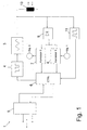
- a control unit 6 serves as higher-level control for the sending and receiving station 1. Furthermore, this preferably leads to 100% amplitude modulation RF signal to the passive transponder 2 energy.
- the information which via an interface 5 from a memory Data processing system flows through a modulator 4 the RF signal of the oscillator 3 by pulse width modulation modulated.
- This type of modulation causes blanking gaps, which have a greater or lesser number of RF vibrations or, in other words, a longer or shorter RF signal follows.
- the signal length after each blanking interval or the number The vibrations are a criterion for a zero or ONE information of the data to be transmitted in the digital system.
- This pulse width modulated, clock-carrying and energy transporting RF signal is shown in Fig. 3. It is according to Fig. 1 decoupled from the oscillator 3 via an antenna coil 10.
- Demodulator 9 which is for the bidirectional, optionally in Full duplex information flow is information about receives the antenna coil 10 and via the correlators 7 and 8 the control unit 6 and the interface 5 to an external Data processing system forwards.
- the modulated according to FIG. 3 Data reaches everyone in the coverage area Transponder at the same time; therefore start after demodulation and decoding of the data, all of them Transponders in sync with their transmissions.
- the different signals of the transponders are in the Transmitting and receiving system to a common resulting Signal composed.
- This overall signal is after demodulation fed to the two correlators 7 and 8.
- This Correlators 7, 8 examine the input signal via a determined period of time predetermined by the control unit 6 after the "0" or "1" waveform and deliver this at the end Period of time, if necessary, an output signal other than ZERO.
- control unit 6 starts transmitting of a command, preferably by specifying bit position and date (0 or 1) initiated a selective process becomes.
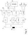
- a passive transponder 2 (Fig. 2) comprises an antenna coil 12 with downstream rectifier 13 (preferably in bridge circuit), voltage regulator 17 and a reset generator 18, the latter blocks the entire transponder circuit if it falls below one, the operation is still reliable ensuring minimum voltage.
- the resulting in the rectifier 13 and in the voltage regulator 17 to a certain value regulated DC voltage serves as supply voltage of the passive transponder 2.
- the energy supply takes place So when the passive transponder 2 approaches the transmitting and receiving station 1 based on the transmitted RF signal.
- the transponder 2 detects the system clock in a clock arrester 14 and demodulates the incoming via the antenna coil 12 Pulse-width modulated RF signal in a demodulator 15. This includes a pause detector to determine the blanking gaps between the signal blocks and a counter that determines the length of the signal block by frequency pulse counting and compares it to a threshold. Short signal blocks, their number of vibrations below a threshold are a ZERO signal, and long signal blocks whose Number of oscillations is above the threshold, a ONE signal in the digital data system. Via a control unit 19 the data arrive in the memory 21.
- control unit 19 In the control unit 19 are all logical functions and Processes of the passive transponder 2 summarized. Depending on Different transmission protocols, Data validation, cryptography, access controls and others logical transitions are implemented. In particular by the control unit 19 the data stream from the memory 21 via the encoder 20 and the modulator 16 and the antenna coil 12 transmitted to the transmitting and receiving station 1. Dependent on the data to be transmitted is a "0" or "1" waveform fed to modulator 16.
- the modulator 16 is a circuit (preferably a transistor) that the voltage at the antenna coil 12 of the transponder in Rhythm of the waveforms supplied by the encoder is loaded.
- the Control unit 19 also contains devices for decoding the commands coming from the transmitting and receiving station 1.
- a selection process namely by transferring a selection command and any long data stream, e.g. Address and data of one Correspond to the memory area in the EEPROM.
- All transponders 2 now compare the incoming one Data stream with the corresponding content of the EEPROM using of a digital comparator. Those transponders where the comparison was positive (i.e. agreement of Data streams) continue to respond to selection commands from the transmitting and receiving station 1, while a negative result a withdrawal of the corresponding transponder from the Selection process.
- memory 21 and comparator 22 and one corresponding instruction set, which is implemented in the control unit 19 is all the necessary tasks for selection of a specific transponder in the work area of a Sending and receiving station 1 are done.
- t 0 is selected in each case. If t 0 is different from 0, the signal shape would be unchanged, it would only be shifted a little on the time axis.
- FIGS. 5a and 5b Other possible functions h0 and h 1 are shown in FIGS. 5a and 5b; these functions can be defined mathematically as follows:
- the functions h 0 and h 1 are constant for one half of the bit time and represent any function g 1 or g 2 in the other half of the bit time, for which: and This can be represented mathematically as follows:
Landscapes
- Engineering & Computer Science (AREA)
- Physics & Mathematics (AREA)
- General Physics & Mathematics (AREA)
- Toxicology (AREA)
- Health & Medical Sciences (AREA)
- Artificial Intelligence (AREA)
- Computer Vision & Pattern Recognition (AREA)
- Theoretical Computer Science (AREA)
- Electromagnetism (AREA)
- General Health & Medical Sciences (AREA)
- Computer Networks & Wireless Communication (AREA)
- Radar Systems Or Details Thereof (AREA)
- Near-Field Transmission Systems (AREA)
- Mobile Radio Communication Systems (AREA)
Claims (7)
- Système de transmission de données sans contact en vue de la transmission de données entre au moins une station émettrice/réceptrice (1) et plusieurs transpondeurs (2), la station d'émission/réception (1) présentant un oscillateur HF (3) en vue de la production d'un signal HF (Fig. 3) pour la transmission d'informations vers les transpondeurs (2) et les transpondeurs (2) présentant des dispositifs de transmission d'informations vers les stations émettrices/réceptrices (1) et la station émettrice/réceptrice (1) présentant par ailleurs un démodulateur (9) en vue de la démodulation du signal transmis par les transpondeurs (2), caractérisé en ce que le produit interne (produit scalaire) du signal (f0) en vue de la transmission d'un ZERO logique et du signal (f1) en vue de la transmission d'un UN logique par le transpondeur (2) vers l'unité d'émission/réception (1) est égal à 0, c'est-à-dire queh (t) étant une fonction de pondération quelconque et T la durée périodique pour la transmission d'un bit et que, dans la station d'émission/réception (1) sont prévus deux corrélateurs (7,8) dont les entrées sont reliées d'une part au démodulateur (9) et, d'autre part, aux générateurs pour les signaux (f0.h ou f1.h).

- Système de transmission de données selon la revendication 1, caractérisé en ce que la station émettrice/réceptrice (1) comporte des dispositifs en vue de la transmission d'énergie et de rythme inductive et sans fil à l'aide d'un seul signal HF produit dans un oscillateur HF (3), des dispositifs de transmission de données par modulation de la largeur d'impulsion de ce signal, au moins un transpondeur passif (2) présentant un redresseur (13) pour le signal HF reçu, un démodulateur de largeur d'impulsion (15), un étage de transmission pour la démodulation de charge du signal HF et une mémoire de données (21) et l'étage de transmission transmettant les données par le fait qu'il module la charge du signal HF à certains moments.
- Système de transmission de données selon l'une des revendications 1 ou 2, caractérisé en ce que h(t) = 1 pour tout t dans la zone de 0 à T.
- Système de transmission de données selon la revendication 3, caractérisé en ce que les deux fonctions ho et h1 suivantes sont sélectionnées pour f0 et f1:les deux fonctions périodiquement avec T (Fig. 4).

- Système de transmission de données selon la revendication 3, caractérisé en ce que les deux fonctions ho et h1 suivantes sont sélectionnées pour f0 et f1: les deux fonctions périodiquement avec T (Fig. 5).

- Système de transmission de données selon la revendication 3, caractérisé en ce que les deux fonctions h0, h1 suivantes sont sélectionnées pour f0 et f1:et
 et, de préférence, g1 = g2 et c1 = c2.
- Système de transmission de données selon la revendication 6, caractérisé en ce que:
Applications Claiming Priority (3)
| Application Number | Priority Date | Filing Date | Title |
|---|---|---|---|
| AT37994 | 1994-02-23 | ||
| AT379/94 | 1994-02-23 | ||
| AT37994A AT401127B (de) | 1994-02-23 | 1994-02-23 | Kontaktloses datenübertragungssystem |
Publications (3)
| Publication Number | Publication Date |
|---|---|
| EP0669591A2 EP0669591A2 (fr) | 1995-08-30 |
| EP0669591A3 EP0669591A3 (fr) | 1997-05-28 |
| EP0669591B1 true EP0669591B1 (fr) | 1999-12-08 |
Family
ID=3489032
Family Applications (1)
| Application Number | Title | Priority Date | Filing Date |
|---|---|---|---|
| EP19950890025 Expired - Lifetime EP0669591B1 (fr) | 1994-02-23 | 1995-02-03 | Système de transmission de données sans contact |
Country Status (5)
| Country | Link |
|---|---|
| EP (1) | EP0669591B1 (fr) |
| AT (1) | AT401127B (fr) |
| DE (1) | DE59507354D1 (fr) |
| DK (1) | DK0669591T3 (fr) |
| ES (1) | ES2143029T3 (fr) |
Cited By (1)
| Publication number | Priority date | Publication date | Assignee | Title |
|---|---|---|---|---|
| WO2004114205A1 (fr) * | 2003-06-25 | 2004-12-29 | Koninklijke Philips Electronics N.V. | Support de donnees et moyen de modification pour la modification de la periode de charge |
Families Citing this family (5)
| Publication number | Priority date | Publication date | Assignee | Title |
|---|---|---|---|---|
| DE19528599C2 (de) * | 1995-08-03 | 1999-05-27 | Siemens Ag | Verfahren zur Zugriffssteuerung von einer Datenstation auf mobile Datenträger |
| FR2741979B1 (fr) | 1995-12-01 | 1998-01-23 | Raimbault Pierre | Procede d'interrogation a distance d'etiquettes station et etiquette pour sa mise en oeuvre |
| ZA981382B (en) * | 1997-03-07 | 1998-08-24 | Kaba Schliesssysteme Ag | High frequency identification medium with passive electronic data carrier |
| DE19736692C2 (de) * | 1997-08-22 | 1999-06-17 | Siemens Ag | Auswählverfahren und Anordnung zum Durchführen dieses Auswählverfahrens |
| EP1064616B1 (fr) | 1999-01-26 | 2003-07-30 | Koninklijke Philips Electronics N.V. | Porteuse de donnees pourvue d'au moins deux etages de decodage |
Family Cites Families (5)
| Publication number | Priority date | Publication date | Assignee | Title |
|---|---|---|---|---|
| NL288711A (fr) * | 1963-02-08 | 1900-01-01 | ||
| NL7511707A (nl) * | 1975-10-06 | 1977-04-12 | Philips Nv | Kruiscorrelatie-inrichting. |
| FR2609813B1 (fr) * | 1987-01-19 | 1989-03-03 | Midi Robois | Procede et systeme d'identification et/ou de localisation, et balise pour la mise en oeuvre dudit procede |
| FR2665038B1 (fr) * | 1990-07-23 | 1994-04-01 | Alcatel Business Systems | Systeme de radio-identification a badges repondeurs, unites constitutives d'un tel systeme et agencement exploitant correspondant. |
| US5354975A (en) * | 1992-07-01 | 1994-10-11 | Tokimec Inc. | Contactless data processing apparatus |
-
1994
- 1994-02-23 AT AT37994A patent/AT401127B/de not_active IP Right Cessation
-
1995
- 1995-02-03 DE DE59507354T patent/DE59507354D1/de not_active Expired - Lifetime
- 1995-02-03 DK DK95890025T patent/DK0669591T3/da active
- 1995-02-03 ES ES95890025T patent/ES2143029T3/es not_active Expired - Lifetime
- 1995-02-03 EP EP19950890025 patent/EP0669591B1/fr not_active Expired - Lifetime
Cited By (1)
| Publication number | Priority date | Publication date | Assignee | Title |
|---|---|---|---|---|
| WO2004114205A1 (fr) * | 2003-06-25 | 2004-12-29 | Koninklijke Philips Electronics N.V. | Support de donnees et moyen de modification pour la modification de la periode de charge |
Also Published As
| Publication number | Publication date |
|---|---|
| EP0669591A2 (fr) | 1995-08-30 |
| ES2143029T3 (es) | 2000-05-01 |
| DE59507354D1 (de) | 2000-01-13 |
| ATA37994A (de) | 1995-10-15 |
| DK0669591T3 (da) | 2000-06-13 |
| EP0669591A3 (fr) | 1997-05-28 |
| AT401127B (de) | 1996-06-25 |
Similar Documents
| Publication | Publication Date | Title |
|---|---|---|
| EP0473569B2 (fr) | Système de transmission de données par voie inductive sans contact | |
| DE3874389T2 (de) | System zum kontaktlosen austausch von daten. | |
| DD269478A5 (de) | Elektronisches datenverarbeitungssystem | |
| EP2284773B2 (fr) | Carte à puce | |
| DE69831057T2 (de) | Multiples etikettenlesesystem | |
| DE69532837T2 (de) | Lese-/Schreibvorrichtung für berührungslose IC-Karte | |
| DE60209386T2 (de) | Kontaktloser integrierter schaltungsleser mit einem aktiv-bereitschafts-modus mit niedriger stromaufnahme | |
| EP0590122B1 (fr) | Procede et systeme de transmission de structures serielles de donnees pour systemes d'identification de supports d'information, ainsi que support d'information | |
| DE69534303T2 (de) | Modulationsschaltung für Vorrichtung zum Lesen und Schreiben einer IC-Karte | |
| EP2256662B1 (fr) | Procédé de détection de supports d'identification | |
| EP1153362B1 (fr) | Systeme de transfert de donnees sans contact et procede pour le transfert de donnees sans contact | |
| EP0960486B1 (fr) | Dispositif de transmission sans contact d'informations et d'energie | |
| EP0441237A1 (fr) | Plaquette détectrice portative programmable par champs | |
| DE60101867T2 (de) | Überprüfung der Anwesenheit eines elektromagnetischen Transponders im Feld eines Lese-Terminals mit Amplitudendemodulation | |
| DE19602316C1 (de) | Vorrichtung zum Übertragen von Daten oder Energie | |
| DE60308529T2 (de) | Antikollisionsverfahren mit zeitschlitzen mit verarbeitung von informationen, die die zeitschlitze markieren | |
| EP0949576B1 (fr) | Support de données et méthode pour une réception sans fil de données et d'énergie | |
| EP0669591B1 (fr) | Système de transmission de données sans contact | |
| DE69230088T2 (de) | Lese/Schreibsystem für Aufzeichnungsmedium und kontaktfreies IC-Karten-System | |
| DE69630830T2 (de) | Datenträger mit hoher Datenübertragungsgeschwindigkeit | |
| DE69619937T2 (de) | Schaltung zur Stromversorgung und Modulation für eine fernabfragbare Karte | |
| EP1470520A1 (fr) | Procede pour transmettre des donnees entre une station de base et un transpondeur | |
| DE102008040453B4 (de) | Vorrichtung zur berührungslosen Kommunikation und Verfahren zur berührungslosen Kommunikation | |
| EP1586917A2 (fr) | Méthode pour faire un choix entre un ou plusieurs répondeurs | |
| EP0496024B1 (fr) | Méthode pour réduire les pertes de puissance dans les appareils pour transmettre des données et l'énergie sans contact et dispositif pour réaliser cette méthode |
Legal Events
| Date | Code | Title | Description |
|---|---|---|---|
| PUAI | Public reference made under article 153(3) epc to a published international application that has entered the european phase |
Free format text: ORIGINAL CODE: 0009012 |
|
| AK | Designated contracting states |
Kind code of ref document: A2 Designated state(s): BE CH DE DK ES FR GB IT LI NL SE |
|
| RAP1 | Party data changed (applicant data changed or rights of an application transferred) |
Owner name: MIKRON AKTIENGESELLSCHAFT FUER INTEGRIERTE MIKROEL |
|
| ITCL | It: translation for ep claims filed |
Representative=s name: STUDIO BIANCHETTI |
|
| EL | Fr: translation of claims filed | ||
| GBC | Gb: translation of claims filed (gb section 78(7)/1977) | ||
| PUAL | Search report despatched |
Free format text: ORIGINAL CODE: 0009013 |
|
| AK | Designated contracting states |
Kind code of ref document: A3 Designated state(s): BE CH DE DK ES FR GB IT LI NL SE |
|
| 17P | Request for examination filed |
Effective date: 19971128 |
|
| GRAG | Despatch of communication of intention to grant |
Free format text: ORIGINAL CODE: EPIDOS AGRA |
|
| 17Q | First examination report despatched |
Effective date: 19990128 |
|
| GRAG | Despatch of communication of intention to grant |
Free format text: ORIGINAL CODE: EPIDOS AGRA |
|
| GRAH | Despatch of communication of intention to grant a patent |
Free format text: ORIGINAL CODE: EPIDOS IGRA |
|
| GRAH | Despatch of communication of intention to grant a patent |
Free format text: ORIGINAL CODE: EPIDOS IGRA |
|
| GRAA | (expected) grant |
Free format text: ORIGINAL CODE: 0009210 |
|
| AK | Designated contracting states |
Kind code of ref document: B1 Designated state(s): BE CH DE DK ES FR GB IT LI NL SE |
|
| REG | Reference to a national code |
Ref country code: CH Ref legal event code: EP |
|
| REF | Corresponds to: |
Ref document number: 59507354 Country of ref document: DE Date of ref document: 20000113 |
|
| RAP2 | Party data changed (patent owner data changed or rights of a patent transferred) |
Owner name: PHILIPS SEMICONDUCTORS GRATKORN GMBH |
|
| GBT | Gb: translation of ep patent filed (gb section 77(6)(a)/1977) |
Effective date: 20000127 |
|
| ITF | It: translation for a ep patent filed | ||
| ET | Fr: translation filed | ||
| NLT2 | Nl: modifications (of names), taken from the european patent patent bulletin |
Owner name: PHILIPS SEMICONDUCTORS GRATKORN GMBH |
|
| RAP2 | Party data changed (patent owner data changed or rights of a patent transferred) |
Owner name: KONINKLIJKE PHILIPS ELECTRONICS N.V. |
|
| REG | Reference to a national code |
Ref country code: ES Ref legal event code: FG2A Ref document number: 2143029 Country of ref document: ES Kind code of ref document: T3 |
|
| NLT2 | Nl: modifications (of names), taken from the european patent patent bulletin |
Owner name: KONINKLIJKE PHILIPS ELECTRONICS N.V. |
|
| REG | Reference to a national code |
Ref country code: DK Ref legal event code: T3 |
|
| NLXE | Nl: other communications concerning ep-patents (part 3 heading xe) |
Free format text: PAT. BUL. 05/2000 PAGE 657 CORR.: KONINKLIJKE PHILIPS ELECTRONICS N.V. |
|
| PLBE | No opposition filed within time limit |
Free format text: ORIGINAL CODE: 0009261 |
|
| STAA | Information on the status of an ep patent application or granted ep patent |
Free format text: STATUS: NO OPPOSITION FILED WITHIN TIME LIMIT |
|
| 26N | No opposition filed | ||
| REG | Reference to a national code |
Ref country code: GB Ref legal event code: IF02 |
|
| REG | Reference to a national code |
Ref country code: GB Ref legal event code: 732E |
|
| REG | Reference to a national code |
Ref country code: GB Ref legal event code: 732E |
|
| REG | Reference to a national code |
Ref country code: FR Ref legal event code: TP |
|
| REG | Reference to a national code |
Ref country code: FR Ref legal event code: GC |
|
| REG | Reference to a national code |
Ref country code: CH Ref legal event code: PUE Owner name: NXP B.V. Free format text: KONINKLIJKE PHILIPS ELECTRONICS N.V.#GROENEWOUDSEWEG 1#5621 BA EINDHOVEN (NL) -TRANSFER TO- NXP B.V.#HIGH TECH CAMPUS 60#5656 AG EINDHOVEN (NL) |
|
| REG | Reference to a national code |
Ref country code: GB Ref legal event code: 732E Free format text: REGISTERED BETWEEN 20090618 AND 20090624 |
|
| REG | Reference to a national code |
Ref country code: FR Ref legal event code: GC |
|
| PG25 | Lapsed in a contracting state [announced via postgrant information from national office to epo] |
Ref country code: IT Free format text: LAPSE BECAUSE OF NON-PAYMENT OF DUE FEES Effective date: 20080203 |
|
| REG | Reference to a national code |
Ref country code: CH Ref legal event code: NV Representative=s name: BRAUNPAT BRAUN EDER AG |
|
| REG | Reference to a national code |
Ref country code: GB Ref legal event code: 732E Free format text: REGISTERED BETWEEN 20101007 AND 20101013 |
|
| REG | Reference to a national code |
Ref country code: FR Ref legal event code: GC |
|
| REG | Reference to a national code |
Ref country code: GB Ref legal event code: 732E Free format text: REGISTERED BETWEEN 20111013 AND 20111019 |
|
| REG | Reference to a national code |
Ref country code: FR Ref legal event code: AU Effective date: 20120126 |
|
| REG | Reference to a national code |
Ref country code: GB Ref legal event code: 732E Free format text: REGISTERED BETWEEN 20120315 AND 20120321 |
|
| REG | Reference to a national code |
Ref country code: GB Ref legal event code: 732E Free format text: REGISTERED BETWEEN 20120705 AND 20120711 |
|
| REG | Reference to a national code |
Ref country code: GB Ref legal event code: 732E Free format text: REGISTERED BETWEEN 20120927 AND 20121003 |
|
| PGFP | Annual fee paid to national office [announced via postgrant information from national office to epo] |
Ref country code: FR Payment date: 20130408 Year of fee payment: 19 |
|
| REG | Reference to a national code |
Ref country code: GB Ref legal event code: 732E Free format text: REGISTERED BETWEEN 20130606 AND 20130612 |
|
| PGFP | Annual fee paid to national office [announced via postgrant information from national office to epo] |
Ref country code: SE Payment date: 20140123 Year of fee payment: 20 Ref country code: BE Payment date: 20140122 Year of fee payment: 20 Ref country code: CH Payment date: 20140123 Year of fee payment: 20 Ref country code: NL Payment date: 20140121 Year of fee payment: 20 Ref country code: DK Payment date: 20140121 Year of fee payment: 20 Ref country code: DE Payment date: 20140122 Year of fee payment: 20 |
|
| PGFP | Annual fee paid to national office [announced via postgrant information from national office to epo] |
Ref country code: ES Payment date: 20140205 Year of fee payment: 20 Ref country code: IT Payment date: 20140130 Year of fee payment: 20 |
|
| PGFP | Annual fee paid to national office [announced via postgrant information from national office to epo] |
Ref country code: GB Payment date: 20140127 Year of fee payment: 20 |
|
| REG | Reference to a national code |
Ref country code: FR Ref legal event code: ST Effective date: 20141031 |
|
| PG25 | Lapsed in a contracting state [announced via postgrant information from national office to epo] |
Ref country code: FR Free format text: LAPSE BECAUSE OF NON-PAYMENT OF DUE FEES Effective date: 20140228 |
|
| REG | Reference to a national code |
Ref country code: DE Ref legal event code: R071 Ref document number: 59507354 Country of ref document: DE |
|
| REG | Reference to a national code |
Ref country code: DK Ref legal event code: EUP Effective date: 20150203 |
|
| REG | Reference to a national code |
Ref country code: NL Ref legal event code: V4 Effective date: 20150203 |
|
| REG | Reference to a national code |
Ref country code: CH Ref legal event code: PL |
|
| REG | Reference to a national code |
Ref country code: GB Ref legal event code: PE20 Expiry date: 20150202 |
|
| REG | Reference to a national code |
Ref country code: SE Ref legal event code: EUG |
|
| REG | Reference to a national code |
Ref country code: ES Ref legal event code: FD2A Effective date: 20150424 |
|
| PG25 | Lapsed in a contracting state [announced via postgrant information from national office to epo] |
Ref country code: GB Free format text: LAPSE BECAUSE OF EXPIRATION OF PROTECTION Effective date: 20150202 |
|
| PG25 | Lapsed in a contracting state [announced via postgrant information from national office to epo] |
Ref country code: ES Free format text: LAPSE BECAUSE OF EXPIRATION OF PROTECTION Effective date: 20150204 |