EP0669591B1 - System for contactless data transmission - Google Patents
System for contactless data transmission Download PDFInfo
- Publication number
- EP0669591B1 EP0669591B1 EP19950890025 EP95890025A EP0669591B1 EP 0669591 B1 EP0669591 B1 EP 0669591B1 EP 19950890025 EP19950890025 EP 19950890025 EP 95890025 A EP95890025 A EP 95890025A EP 0669591 B1 EP0669591 B1 EP 0669591B1
- Authority
- EP
- European Patent Office
- Prior art keywords
- signal
- transponders
- transmitter
- data transmission
- transponder
- Prior art date
- Legal status (The legal status is an assumption and is not a legal conclusion. Google has not performed a legal analysis and makes no representation as to the accuracy of the status listed.)
- Expired - Lifetime
Links
Images

Classifications
-
- G—PHYSICS
- G06—COMPUTING; CALCULATING OR COUNTING
- G06K—GRAPHICAL DATA READING; PRESENTATION OF DATA; RECORD CARRIERS; HANDLING RECORD CARRIERS
- G06K7/00—Methods or arrangements for sensing record carriers, e.g. for reading patterns
- G06K7/10—Methods or arrangements for sensing record carriers, e.g. for reading patterns by electromagnetic radiation, e.g. optical sensing; by corpuscular radiation
- G06K7/10009—Methods or arrangements for sensing record carriers, e.g. for reading patterns by electromagnetic radiation, e.g. optical sensing; by corpuscular radiation sensing by radiation using wavelengths larger than 0.1 mm, e.g. radio-waves or microwaves
- G06K7/10019—Methods or arrangements for sensing record carriers, e.g. for reading patterns by electromagnetic radiation, e.g. optical sensing; by corpuscular radiation sensing by radiation using wavelengths larger than 0.1 mm, e.g. radio-waves or microwaves resolving collision on the communication channels between simultaneously or concurrently interrogated record carriers.
- G06K7/10029—Methods or arrangements for sensing record carriers, e.g. for reading patterns by electromagnetic radiation, e.g. optical sensing; by corpuscular radiation sensing by radiation using wavelengths larger than 0.1 mm, e.g. radio-waves or microwaves resolving collision on the communication channels between simultaneously or concurrently interrogated record carriers. the collision being resolved in the time domain, e.g. using binary tree search or RFID responses allocated to a random time slot
- G06K7/10039—Methods or arrangements for sensing record carriers, e.g. for reading patterns by electromagnetic radiation, e.g. optical sensing; by corpuscular radiation sensing by radiation using wavelengths larger than 0.1 mm, e.g. radio-waves or microwaves resolving collision on the communication channels between simultaneously or concurrently interrogated record carriers. the collision being resolved in the time domain, e.g. using binary tree search or RFID responses allocated to a random time slot interrogator driven, i.e. synchronous
-
- G—PHYSICS
- G06—COMPUTING; CALCULATING OR COUNTING
- G06K—GRAPHICAL DATA READING; PRESENTATION OF DATA; RECORD CARRIERS; HANDLING RECORD CARRIERS
- G06K7/00—Methods or arrangements for sensing record carriers, e.g. for reading patterns
- G06K7/0008—General problems related to the reading of electronic memory record carriers, independent of its reading method, e.g. power transfer
Definitions
- the present invention relates to a contactless data transmission system between at least one transmitting and receiving station and a plurality of transponders, the transmitting and receiving station having an HF oscillator for generating an HF signal for transmitting information to the transponders, and the transponder devices for transmitting information to the transmitter - Have and receiving station, in particular a transmission stage for modulating the load of the RF signal transmitted by the transmitting and receiving station, and furthermore the transmitting and receiving station has a demodulator for demodulating the signal transmitted by the transponders.
- Such a data transmission system is from Austria Patent No. 395,224 known.
- Examples of use for this are the automatic road toll collection by automatic Contact debiting as soon as a transponder on the vehicle a sending and receiving station of a toll station passes.
- Identities can be controlled in read only mode and access control systems enable the determination the scope of a blocking authorization and log it the individual access.
- the control can individual tools provided transponders can be made where the transponder data parameters about tool type and service life including error correction information convey.
- active transponders are not through the electromagnetic field of a transmitting and receiving station supplied with energy, but from a self-sufficient energy source, such as. a battery or a photocell.
- a self-sufficient energy source such as. a battery or a photocell.
- data transmission system known from Austrian Patent No. 395 224 only passive transponders are provided. These work in broadcast mode with load modulation, what enables a reduction in the required components, so that the transponder on a single semiconductor device can be integrated and can be produced very inexpensively is. Due to progress in development of energy-saving circuit technology lately succeeded in producing passive transponders with a long range. Such transponders are preferably used in so-called "Hands-free" access control systems used (e.g. ski lift access control).
- transponders Is one or more transponders from the interviewed Group in the vicinity of the sending and receiving station, so they answer by transferring their individual Codes and some check bits to the sending and receiving station. If only one transponder answers, it is already there identified. If several transponders respond, the result is a synchronous overlay of responses to what's related recognized with the check bits from the sending and receiving station becomes. Now the sending and receiving station starts one further query, the group of transponders surveyed is reduced by half again. This happens so long until only one transponder answers. Answer one Query no transponder, so with the subdivision the complementary transponder group continued.
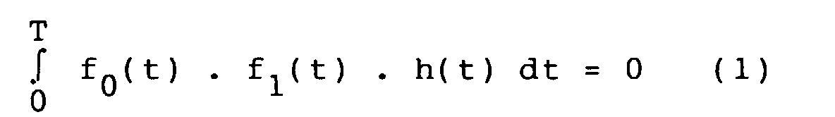
- This object is achieved in that the inner product (scalar product) of the signal f 0 for the transmission of a logical ZERO and the signal f 1 for the transmission of a logical ONE from the transponder to the transmitting and receiving station is equal to 0, ie applies, where h (t) is an arbitrary weight function and T is the period for the transmission of one bit, and that two correlators are provided in the transmitting and receiving station, the inputs of which are on the one hand with the demodulator and on the other hand with generators for signals f 0 .h or f 1 .h are connected.
- the inner product of the two signals is 0, it is possible to determine in the transmitting and receiving station with one correlator each by scalar multiplication of the received signal by f 0 .h or f 1 .h whether a transponder ( or from several transponders) a 0 or a 1 was sent. If there is only one transponder in the detection range, only one or the other correlator can generate a signal not equal to 0, because one and the same transponder only ever sends either a bit 0 or a bit 1 at the same time.
- h (t) 1 (for all t).
- the incoming signal in the correlator can be multiplied by f 0 or f 1 in the transmitting and receiving station, ie by the same signals that are generated by the transponders.
- a control unit 6 serves as higher-level control for the sending and receiving station 1. Furthermore, this preferably leads to 100% amplitude modulation RF signal to the passive transponder 2 energy.
- the information which via an interface 5 from a memory Data processing system flows through a modulator 4 the RF signal of the oscillator 3 by pulse width modulation modulated.
- This type of modulation causes blanking gaps, which have a greater or lesser number of RF vibrations or, in other words, a longer or shorter RF signal follows.
- the signal length after each blanking interval or the number The vibrations are a criterion for a zero or ONE information of the data to be transmitted in the digital system.
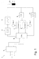
- This pulse width modulated, clock-carrying and energy transporting RF signal is shown in Fig. 3. It is according to Fig. 1 decoupled from the oscillator 3 via an antenna coil 10.
- Demodulator 9 which is for the bidirectional, optionally in Full duplex information flow is information about receives the antenna coil 10 and via the correlators 7 and 8 the control unit 6 and the interface 5 to an external Data processing system forwards.
- the modulated according to FIG. 3 Data reaches everyone in the coverage area Transponder at the same time; therefore start after demodulation and decoding of the data, all of them Transponders in sync with their transmissions.
- the different signals of the transponders are in the Transmitting and receiving system to a common resulting Signal composed.
- This overall signal is after demodulation fed to the two correlators 7 and 8.
- This Correlators 7, 8 examine the input signal via a determined period of time predetermined by the control unit 6 after the "0" or "1" waveform and deliver this at the end Period of time, if necessary, an output signal other than ZERO.
- control unit 6 starts transmitting of a command, preferably by specifying bit position and date (0 or 1) initiated a selective process becomes.
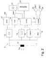
- a passive transponder 2 (Fig. 2) comprises an antenna coil 12 with downstream rectifier 13 (preferably in bridge circuit), voltage regulator 17 and a reset generator 18, the latter blocks the entire transponder circuit if it falls below one, the operation is still reliable ensuring minimum voltage.
- the resulting in the rectifier 13 and in the voltage regulator 17 to a certain value regulated DC voltage serves as supply voltage of the passive transponder 2.
- the energy supply takes place So when the passive transponder 2 approaches the transmitting and receiving station 1 based on the transmitted RF signal.
- the transponder 2 detects the system clock in a clock arrester 14 and demodulates the incoming via the antenna coil 12 Pulse-width modulated RF signal in a demodulator 15. This includes a pause detector to determine the blanking gaps between the signal blocks and a counter that determines the length of the signal block by frequency pulse counting and compares it to a threshold. Short signal blocks, their number of vibrations below a threshold are a ZERO signal, and long signal blocks whose Number of oscillations is above the threshold, a ONE signal in the digital data system. Via a control unit 19 the data arrive in the memory 21.
- control unit 19 In the control unit 19 are all logical functions and Processes of the passive transponder 2 summarized. Depending on Different transmission protocols, Data validation, cryptography, access controls and others logical transitions are implemented. In particular by the control unit 19 the data stream from the memory 21 via the encoder 20 and the modulator 16 and the antenna coil 12 transmitted to the transmitting and receiving station 1. Dependent on the data to be transmitted is a "0" or "1" waveform fed to modulator 16.
- the modulator 16 is a circuit (preferably a transistor) that the voltage at the antenna coil 12 of the transponder in Rhythm of the waveforms supplied by the encoder is loaded.
- the Control unit 19 also contains devices for decoding the commands coming from the transmitting and receiving station 1.
- a selection process namely by transferring a selection command and any long data stream, e.g. Address and data of one Correspond to the memory area in the EEPROM.
- All transponders 2 now compare the incoming one Data stream with the corresponding content of the EEPROM using of a digital comparator. Those transponders where the comparison was positive (i.e. agreement of Data streams) continue to respond to selection commands from the transmitting and receiving station 1, while a negative result a withdrawal of the corresponding transponder from the Selection process.
- memory 21 and comparator 22 and one corresponding instruction set, which is implemented in the control unit 19 is all the necessary tasks for selection of a specific transponder in the work area of a Sending and receiving station 1 are done.
- t 0 is selected in each case. If t 0 is different from 0, the signal shape would be unchanged, it would only be shifted a little on the time axis.
- FIGS. 5a and 5b Other possible functions h0 and h 1 are shown in FIGS. 5a and 5b; these functions can be defined mathematically as follows:
- the functions h 0 and h 1 are constant for one half of the bit time and represent any function g 1 or g 2 in the other half of the bit time, for which: and This can be represented mathematically as follows:
Description
Die vorliegende Erfindung betrifft ein kontaktloses Datenübertragungssystem zwischen mindestens einer Sende- und Empfangsstation und mehreren Transpondern, wobei die Sende- und Empfangsstation einen HF-Oszillator zur Erzeugung eines HF-Signals zur Informationsübertragung zu den Transpondern aufweist und wobei die Transponder Einrichtungen zur Informationsübertragung zu der Sende- und Empfangsstation aufweisen, insbesondere eine Sendestufe zur Belastungsmodulation des von der Sende- und Empfangsstation ausgesandten HF-Signals, und wobei weiters die Sende- und Empfangsstation einen Demodulator zum Demodulieren des von den Transpondern ausgesandten Signals aufweist.The present invention relates to a contactless data transmission system between at least one transmitting and receiving station and a plurality of transponders, the transmitting and receiving station having an HF oscillator for generating an HF signal for transmitting information to the transponders, and the transponder devices for transmitting information to the transmitter - Have and receiving station, in particular a transmission stage for modulating the load of the RF signal transmitted by the transmitting and receiving station, and furthermore the transmitting and receiving station has a demodulator for demodulating the signal transmitted by the transponders.
Ein derartiges Datenübertragungssystem ist aus dem österreichischen Patent Nr. 395 224 bekannt. Anwendungsbeispiele dafür sind die automatische Straßenmauteinhebung durch selbsttätige Kontaktabbuchung, sobald ein fahrzeugseitiger Transponder eine Sende- und Empfangsstation einer Mautstelle passiert. Identitätsweise können in Read Only-Betriebsweise kontrolliert werden und Zutrittskontrollsysteme ermöglichen die Ermittlung des Umfanges einer Sperrberechtigung und protokollieren die individuellen Zutritte. Bei Werkzeugwechselsystemen auf Werkzeugmaschinen kann die Steuerung aufgrund der an den einzelnen Werkzeugen vorgesehen Transponder vorgenommen werden, wobei die Transponderdaten Kenngrößen über Werkzeugtype und Standzeit einschließlich einer Fehlerkorrekturinformation vermitteln.Such a data transmission system is from Austria Patent No. 395,224 known. Examples of use for this are the automatic road toll collection by automatic Contact debiting as soon as a transponder on the vehicle a sending and receiving station of a toll station passes. Identities can be controlled in read only mode and access control systems enable the determination the scope of a blocking authorization and log it the individual access. For tool changing systems on machine tools, the control can individual tools provided transponders can be made where the transponder data parameters about tool type and service life including error correction information convey.
Allgemein können bei solchen Datenübertragungssystemen passive Transponder (ohne eigene Energieversorgung) oder aktive Transponder (mit eigener Energieversorgung) eingesetzt werden. Passive Transponder können kleiner und kostengünstiger hergestellt werden, sie haben aber im Vergleich zu aktiven Transpondern nur eine verhältnismäßig geringe Reichweite, weil sie ihren Energiebedarf aus dem von der Sende- und Empfangsstation ausgesendeten HF-Signal decken müssen.In general, with such data transmission systems passive transponders (without their own energy supply) or active ones Transponder (with its own energy supply) used become. Passive transponders can be smaller and less expensive are produced, but they have compared to active Transponders only a relatively short range, because it gets its energy from that of the sending and receiving station emitted RF signal must cover.
Im Gegensatz dazu werden aktive Transponder nicht durch das elektromagnetische Feld einer Sende- und Empfangsstation mit Energie versorgt, sondern aus einer autarken Energiequelle, wie z.B. einer Batterie oder einer Fotozelle. Bei dem aus dem österreichischen Patent Nr. 395 224 bekannten Datenübertragungssystem sind nur passive Transponder vorgesehen. Diese arbeiten im Sendebetrieb mit Belastungsmodulation, was eine Reduktion der erforderlichen Komponenten ermöglicht, sodaß der Transponder auf einem einzelnen Halbleiterbaustein integriert werden kann und solcherart sehr kostengünstig herstellbar ist. Aufgrund von Fortschritten bei der Entwicklung von energiesparender Schaltungstechnik ist es in letzter Zeit gelungen, passive Transponder mit großer Reichtweite herzustellen. Solche Transponder werden vorzugsweise bei sogenanten "Handsfree"-Zutrittkontrollsystemen eingesetzt (z.B. Skilift-Zutrittskontrolle).In contrast, active transponders are not through the electromagnetic field of a transmitting and receiving station supplied with energy, but from a self-sufficient energy source, such as. a battery or a photocell. In which data transmission system known from Austrian Patent No. 395 224 only passive transponders are provided. These work in broadcast mode with load modulation, what enables a reduction in the required components, so that the transponder on a single semiconductor device can be integrated and can be produced very inexpensively is. Due to progress in development of energy-saving circuit technology lately succeeded in producing passive transponders with a long range. Such transponders are preferably used in so-called "Hands-free" access control systems used (e.g. ski lift access control).
Befinden sich mehrere passive Transponder im Feld einer Sende- und Empfangsstation, so kommt es durch Überlagerung von Aussendungen von verschiedenen Transpondern zu Informationsverfälschungen. Es können zwar diese Informationsverfälschungen in der Kontrolleinheit einer Sende- und Empfangsstation erkannt werden und zudem ist durch ein geeignetes Abfrage-/Antwort-Verfahren (wie in dem Patent Nr. 395 224 beschrieben) eine Identifizierung aller im Erfassungsbereich einer Sende- und Empfangsstation befindlichen Transponder möglich: Sobald die Sende- und Empfangsstation durch das Anwesenheitsprotokoll die Anwesenheit von mehreren Transpondern festgestellt hat, beginnt die Abfrage, ob sich ein Transponder aus einer Hälfte der Gesamtanzahl von Transpondern im Erfassungsbereich der Sende- und Empfangsstation befindet. Dies geschieht, indem die Sende- und Empfangsstation ein Abfrageprotokoll sendet. Befindet sich ein Transponder oder mehrere aus der befragten Gruppe im Nahbereich der Sende- und Empfangsstation, so antworten diese durch Übertragung ihres individuellen Codes und einiger Prüfbits an die Sende- und Empfangsstation. Antwortet nur ein Transponder, so ist dieser damit bereits identifiziert. Antworten mehrere Transponder, so ergibt sich eine synchrone Überlagerung der Antworten, was im Zusammenhang mit den Prüfbits von der Sende- und Empfangsstation erkannt wird. Nun startet die Sende- und Empfangsstation eine weitere Abfrage, wobei die befragte Gruppe von Transpondern wieder um die Hälfte reduziert wird. Dies geschieht so lange, bis nur mehr ein Transponder antwortet. Antwortet auf eine Abfrage hin kein Transponder, so wird mit der Unterteilung der komplementären Transpondergruppe fortgesetzt.If there are several passive transponders in the field of a transmission and receiving station, so it comes from superimposing Transmissions from various transponders to falsify information. It can be this falsification of information in the control unit of a sending and receiving station be recognized and also by a suitable query / response procedure (as described in Patent No. 395 224) an identification of all in the coverage area of a transmission transponder and receiving station possible: As soon as the sending and receiving station through the presence protocol the presence of several transponders is determined has, the query begins whether a transponder is from a Half of the total number of transponders in the detection area the sending and receiving station. This is done by the sending and receiving station sends a query protocol. Is one or more transponders from the interviewed Group in the vicinity of the sending and receiving station, so they answer by transferring their individual Codes and some check bits to the sending and receiving station. If only one transponder answers, it is already there identified. If several transponders respond, the result is a synchronous overlay of responses to what's related recognized with the check bits from the sending and receiving station becomes. Now the sending and receiving station starts one further query, the group of transponders surveyed is reduced by half again. This happens so long until only one transponder answers. Answer one Query no transponder, so with the subdivision the complementary transponder group continued.
Dieses bekannte Verfahren stellt allerdings nur einen prinzipiellen Lösungsansatz dar. In der Praxis eingesetzt würde die Unterteilung in Gruppen sehr zeitintensiv sein, weil zur Identifizierung eines Transponders bis zu 2logN Abfragen (N Gesamtzahl aller Transponder, nicht nur der Transponder, die sich im Erfassungsbereich der Sende- und Empfangsstation befinden) notwendig sind.However, this known method only represents a basic approach. In practice, subdivision into groups would be very time-consuming because up to 2 logN queries (N total number of all transponders, not just the transponders that are within the detection range of the transponder) were used to identify a transponder Sender and receiver station) are necessary.
Es ist Aufgabe der vorliegenden Erfindung, ein Datenübertragungssystem der eingangs genannten Art derart zu verbessern, daß die Auswahl eines aus mehreren, im Erfassungsbereich eines Sende- und Empfangsgerätes befindlichen Transponders sehr zeiteffizient und damit praktikabel ist.It is an object of the present invention to provide a data transmission system to improve the type mentioned at the beginning, that the selection of one from several, in the detection area a transponder located in a transmitting and receiving device is very time efficient and therefore practical.
Diese Aufgabe wird erfindungsgemäß dadurch gelöst, daß
das innere Produkt (Skalarprodukt) des Signales f0 zur Übertragung
einer logischen NULL und des Signales f1 zur Übertragung
einer logischen EINS vom Transponder zur Sende- und Empfangsstation
gleich 0 ist, d.h. daß

Dadurch, daß das innere Produkt der beiden Signale 0 ist,
ist es möglich, in der Sende- und Empfangsstation mit jeweils
einem Korrelator durch skalare Multiplikation des empfangenen
Signales mit f0.h bzw. f1.h festzustellen, ob von einem Transponder
(oder von mehreren Transpondern) eine 0 oder eine 1
gesendet wurde. Wenn nur ein Transponder im Erfassungsbereich
vorhanden ist, kann jeweils nur der eine oder der andere Korrelator
ein Signal ungleich 0 erzeugen, weil ein und derselbe
Transponder zur selben Zeit immer nur entweder ein Bit 0 oder
ein Bit 1 sendet. Wenn jedoch zumindest zwei Transponder anwesend
sind, so muß sich ihr Identifikationssignal in mindestens
einem Bit unterscheiden, d.h. an dieser Stelle werden
gleichzeitig ein Bit 0 und ein Bit 1 übertragen, sodaß beide
Korrelatoren ein Signal ungleich liefern. Damit kann erkannt
werden, an welchen Bitpositionen Kollisionen auftreten. Damit
sind zur Identifizierung eines Transponders maximal so viele
Zyklen notwendig, wie Transponder im Erfassungsbereich vorhanden
sind (im allgemeinen höchstens 3 oder 5);im Gegensatz dazu
sind bei dem oben beschriebenen bekannten System bis zu 2logN
Zyklen notwendig, wobei N die Gesamtzahl aller Transponder ist
(bei größeren Systemen 10.000 oder 100.000 oder noch mehr),
sodaß hier 14, 17 oder noch mehr Zyklen erforderlich sein können,
selbst wenn nur zwei Transponder im Erfassungsbereich vorhanden
sind.Because the inner product of the two signals is 0, it is possible to determine in the transmitting and receiving station with one correlator each by scalar multiplication of the received signal by f 0 .h or f 1 .h whether a transponder ( or from several transponders) a 0 or a 1 was sent. If there is only one transponder in the detection range, only one or the other correlator can generate a signal not equal to 0, because one and the same transponder only ever sends either a
Es ist normalerweise am einfachsten, wenn man h(t) = 1 wählt (für alle t). In diesem Fall kann in der Sende- und Empfangsstation das einfallende Signal in den Korrelator mit f0 bzw. f1 multipliziert werden, d.h. mit denselben Signalen, die von den Transpondern erzeugt werden. It is usually easiest to choose h (t) = 1 (for all t). In this case, the incoming signal in the correlator can be multiplied by f 0 or f 1 in the transmitting and receiving station, ie by the same signals that are generated by the transponders.
Spezielle, für das erfindungsgemäße Datenübertragungssystem
geeignete orthogonale Signalformen sind in den Unteransprüchen
beschrieben und werden anhand der Figuren näher
erläutert.
Gemäß Fig. 1 wird in einer Sende- und Empfangsstation 1
in einem Oszillator 3 ein HF-Signal zur Übertragung von Energie,
Takt und Information an einen Transponder 2 (Fig. 2) generiert.
Die Frequenz des HF-Signales führt den Systemtakt
(Zeitbasis) sowohl in der Sende- und Empfangsstation 1 als
auch im passiven Transponder 2. Dieser Systemtakt wird in
der Sende- und Empfangsstation 1 aus dem HF-Signal des Oszillators
3 in einem Taktableiter 11 gewonnen. Der Taktableiter
11 ist als Aufbereitungsschaltung zu verstehen, in der das
empfangene Energiesignal in den digitalen Systemtakt derselben
Frequenz umgewandelt wird. Eine Steuereinheit 6 dient als
übergeordnete Steuerung für die Sende- und Empfangsstation 1.
Ferner führt das vorzugsweise zu 100% amplitudenmodulierte
HF-Signal dem passiven Transponder 2 Energie zu. Die Information,
die über eine Schnittstelle 5 aus einem Speicher einer
Datenverarbeitungsanlage fließt, wird über einen Modulator
4 dem HF-Signal des Oszillators 3 durch Pulsweitenmodulation
aufmoduliert. Diese Modulationsart bewirkt Austastlücken,
welchen eine größere oder kleinere Anzahl von HF-Schwingungen
bzw., anders ausgedrückt, ein längeres oder kürzeres HF-Signal
folgt. Die Signallänge nach jeder Austastlücke bzw. die Anzahl
der Schwingungen sind ein Kriterium für eine NULL- oder
EINS-Information der im Digitalsystem zu übertragenden Daten.
Dieses pulsweitenmodulierte, taktführende und energietransportierende
HF-Signal ist in Fig. 3 dargestellt. Es wird gemäß
Fig. 1 über eine Antennenspule 10 vom Oszillator 3 ausgekoppelt.
Die Schaltung nach Fig. 1 zeigt ferner noch einen
Demodulator 9, der für den bidirektionalen, gegebenenfalls in
Vollduplex erfolgenden Informationsfluß eine Information über
die Antennenspule 10 erhält und über die Korrelatoren 7 und 8
der Steuereinheit 6 und der Schnittstelle 5 zu einer externen
Datenverarbeitungsanlage weiterleitet. Die gemäß Fig. 3 modulierten
Daten erreichen sämliche im Erfassungsbereich befindlichen
Transponder zum gleichen Zeitpunkt; demzufolge beginnen
nach Demodulation und Dekodierung der Daten auch alle
Transponder synchron mit ihren Aussendungen.1 is in a transmitting and receiving station 1st
in an
Die verschiedenen Signale der Transponder werden in der
Sende- und Empfangsanlage zu einem gemeinsamen resultierenden
Signal zusammengesetzt. Dieses Gesamtsignal wird nach Demodulation
den beiden Korrelatoren 7 und 8 zugeführt. Diese
Korrelatoren 7, 8 untersuchen das Eingangssignal über einen
bestimmten, von der Steuereinheit 6 vorgegebenen Zeitraum
nach der "0" oder "1" Signalform und liefern am Ende dieses
Zeitraumes gegebenenfalls ein von NULL verschiedenes Ausgangssignal.
Es ist wichtig, daß die Signalformen für "0" und "1"
so gewählt werden, daß das Skalarprodukt bzw. das
innere Produkt gleich 0 ist, denn nur in diesem Fall liefert
der Korrelator 7 nur dann ein Ausgangssignal, falls ein "0"
Signal am Eingang liegt; falls ein "1" Signal am Eingang dieses
Korrelators liegt, liefert dieses unabhängig von seiner
Amplitude kein Ausgangssignal. Das gleiche gilt sinngemäß
für den Korrelator 8. Beispiele für mögliche Signalformen
sind in Fig. 4 bis 6 gegeben. Die Steuereinheit 6 überprüft
nun den von den Korrelatoren 7 und 8 gelieferten Datenstrom.
Wenn die Korrelatoren 7 und 8 abwechselnd Ausgangssignale
liefern, ist der Datenstrom von allen im Erfassungsbereich
befindlichen Transpondern gleich. Sobald zu einem bestimmten
Zeitpunkt beide Korrelatoren 7 und 8 ein Ausgangssignal liefern,
ist an dieser Bitposition eine Kollision entstanden.The different signals of the transponders are in the
Transmitting and receiving system to a common resulting
Signal composed. This overall signal is after demodulation
fed to the two
In der Folge beginnt die Steuereinheit 6 mit der Aussendung eines Kommandos, wobei vorzugsweise durch Angabe von Bitposition und Datum (0 oder 1) ein Selektivvorgang eingeleitet wird.As a result, the control unit 6 starts transmitting of a command, preferably by specifying bit position and date (0 or 1) initiated a selective process becomes.
Ein passiver Transponder 2 (Fig. 2) umfaßt eine Antennenspule
12 mit nachgeschaltetem Gleichrichter 13 (vorzugsweise
in Brückenschaltung), Spannungsregler 17 sowie einem Resetgenerator
18, letzterer sperrt die gesamte Transponderschaltung
bei Unterschreiten einer den Betrieb noch zuverlässig
gewährleistenden Minimalspannung. Die im Gleichrichter 13 entstehende
und im Spannungsregler 17 auf einen bestimmten Wert
heruntergeregelte Gleichspannung dient als Versorgungsspannung
des passiven Transponders 2. Die Energieversorgung erfolgt
also bei Annäherung des passiven Transponders 2 an die Sende-
und Empfangsstation 1 aufgrund des übertragenen HF-Signales.A passive transponder 2 (Fig. 2) comprises an
Der Transponder 2 erfaßt den Systemtakt in einem Taktableiter
14 und demoduliert das über die Antennenspule 12 einlangende
pulsweitenmodulierte HF-Signal in einem Demodulator 15.
Dieser umfaßt einen Pausendetektor zur Feststellung der Austastlücken
zwischen den Signalblöcken und einen Zähler, der
die Länge des Signalblockes durch Frequenzimpulszählung feststellt
und mit einem Schwellenwert vergleicht. Kurze Signalblöcke,
deren Schwingungsanzahl unter einem Schwellenwert
liegt, stellen ein NULL-Signal, und lange Signalblöcke, deren
Schwingungsanzahl über dem Schwellenwert liegt, ein EINS-Signal
im digitalen Datensystem dar. Über eine Steuerheit 19
gelangen die Daten in den Speicher 21.The
In der Steuereinheit 19 sind alle logischen Funktionen und
Abläufe des passiven Transponders 2 zusammengefaßt. Je nach
Anwendung können unterschiedliche Übertragungsprotokolle,
Datenprüfung, Kryptographie, Zugriffskontrollen und andere
logische Vergänge implementiert werden. Im besonderen wird
durch die Steuereinheit 19 der Datenstrom vom Speicher 21
über den Koder 20 und den Modulator 16 und die Antennenspule
12 zur Sende- und Empfangsstation 1 übertragen. In Abhängigkeit
der zu übertragenden Daten wird über den Koder eine "0"-oder
"1"-Signalform an den Modulator 16 gespeist. Der Modulator
16 ist eine Schaltung (vorzugsweise ein Transistor), die
die Spannung an der Antennenspule 12 des Transponders im
Rhythmus der vom Koder gelieferten Signalformen belastet. Die
Steuereinheit 19 enthält auch Einrichtungen zur Dekodierung
der von der Sende- und Empfangsstation 1 kommendenBefehle.
Insbesondere wird im Falle von Kollisionen von Aussendungen
bei mehreren Transpondern 2 im Bereich einer Sende- und Empfangsstation
1 ein Selektiervorgang eingeleitet, und zwar
durch Übertragung eines Selektierkommandos sowie eines beliebig
langen Datenstromes, dem z.B. Adresse und Daten eines
Speicherbereiches im EEPROM entsprechen.In the
Sämtliche Transponder 2 vergleichen nun den einlaufenden
Datenstrom mit dem entsprechenden Inhalt des EEPROMs mit Hilfe
eines digitalen Komparators. Jene Transponder, bei denen
der Vergleich positiv abgelaufen ist (d.h. Übereinstimmung der
Datenströme), antworten weiterhin auf Selektierkommandos von
der Sende- und Empfangsstation 1, während ein negatives Resultat
ein Ausscheiden der entsprechenden Transponder aus dem
Selektiervorgang zur Folge hat. Somit können mit den Elementen
Steuereinheit 19, Speicher 21 und Komparator 22 und einem
entsprechenden Befehlsatz, der in der Steuereinheit 19 implementiert
ist, sämtliche notwendigen Aufgaben zur Selektierung
eines bestimmten Transponders im Arbeitsbereich einer
Sende- und Empfangsstation 1 erledigt werden.All
Wie bereits erwähnt, ist es gemäß der vorliegenden Erfindung
wesentlich, daß das Skalarprodukt von der Signalform f0
für die "0" mit der Signalform f1 für die "1" gleich 0 ist:

In Fig. 4 ist unter a) folgende Funktion h0 und unter b)
folgende Funktion h1 dargestellt:


Andere mögliche Funktionen h0 und h1 sind in Fig. 5a bzw.
5b dargestellt; diese Funktionen lassen sich mathematisch wie
folgt definieren:


Besonders bevorzugt ist jedoch, wenn die Funktionen h0 und
h1 jeweils für eine Hälfte der Bitzeit konstant sind und in
der jeweils anderen Hälfte der Bitzeit eine beliebige Funktion
g1 bzw. g2 darstellen, für die gilt:

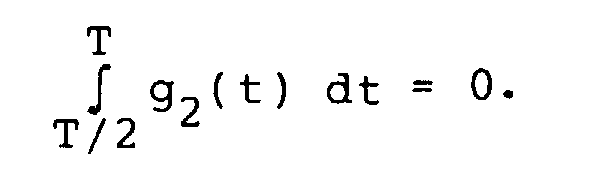


Zur Vereinfachung der Schaltung ist es natürlich zweckmäßig, wenn gilt: g1 = g2 und c1 = c2.To simplify the circuit, it is of course expedient if: g 1 = g 2 and c 1 = c 2 .
In einfacher Weise wird man für g1 und g2 jeweils eine
Rechteckfunktion nehmen, deren Priodendauer ein Teil der
Bitperiode ist; mathematisch ausgedrückt heißt dies:

Claims (7)
- A contactless data transmission system for the transmission of data between at least one transmitter and receiver station (1) and a plurality of transponders (2), the transmitter and receiver station (1) including an RF oscillator (3) for generating an RF signal (Fig. 3) for the transmission of information to the transponders (2), the transponders (2) including devices for the transmission of information to the transmitter and receiver station (1), the transmitter and receiver station (1) also including a demodulator (9) for demodulating the signal transmitted by the transponders (2), characterized in that the inner product (scalar product) of the signal (f0) for transmitting a logic ZERO and the signal (f1) for transmitting a logic ONE from the transponder (2) to the transmitter and receiver station (1) equals zero, i.e. thatwhere h(t) is an arbitrary weighting function and T is the period time for the transmission of one bit, and that the transmitter and receiver station (1) includes two correlators (7, 8) whose inputs are connected to the demodulator (9) on the one side and to generators for signals f0.h and f1.h on the other side

- A data transmission system as claimed in claim 1, characterized in that the transmitter and receiver station (1) includes devices for the inductive, contactless transmission of power and clock signals by means of a single RF signal which is generated in an RF oscillator (3), devices for data transmission by pulse width modulation of this signal, at least one passive transponder (2) being provided with a rectifier (13) for the received RF signal, a pulse width demodulator (15) a transmitter stage for load modulation of the RF signal and a data memory (21), the transmitter stage transmitting the data in that it load modulates the RF signal at given instants.
- A data transmission system as claimed in Claim 1 or 2, characterized in that h(t) = 1 for all t in the range of from 0 to T.
- A data transmission system as claimed in Claim 3, characterized in that the following two functions h0, h1 are selected for f0 and f1:
- A data transmission system as claimed in claim 3, characterized in that the following two functions h0, h1 are selected for f0 and f1:
- A data transmission system as claimed in Claim 3, characterized in that the following two functions h0, h1 are selected for f0 and f1:and
 and where preferably g1 = g2 and c1 = c2.
- A data transmission system as claimed in Claim 6, characterized in that the following holds:
Applications Claiming Priority (3)
| Application Number | Priority Date | Filing Date | Title |
|---|---|---|---|
| AT37994A AT401127B (en) | 1994-02-23 | 1994-02-23 | CONTACTLESS DATA TRANSFER SYSTEM |
| AT379/94 | 1994-02-23 | ||
| AT37994 | 1994-02-23 |
Publications (3)
| Publication Number | Publication Date |
|---|---|
| EP0669591A2 EP0669591A2 (en) | 1995-08-30 |
| EP0669591A3 EP0669591A3 (en) | 1997-05-28 |
| EP0669591B1 true EP0669591B1 (en) | 1999-12-08 |
Family
ID=3489032
Family Applications (1)
| Application Number | Title | Priority Date | Filing Date |
|---|---|---|---|
| EP19950890025 Expired - Lifetime EP0669591B1 (en) | 1994-02-23 | 1995-02-03 | System for contactless data transmission |
Country Status (5)
| Country | Link |
|---|---|
| EP (1) | EP0669591B1 (en) |
| AT (1) | AT401127B (en) |
| DE (1) | DE59507354D1 (en) |
| DK (1) | DK0669591T3 (en) |
| ES (1) | ES2143029T3 (en) |
Cited By (1)
| Publication number | Priority date | Publication date | Assignee | Title |
|---|---|---|---|---|
| WO2004114205A1 (en) * | 2003-06-25 | 2004-12-29 | Koninklijke Philips Electronics N.V. | Data carrier with modification means for modifying the load period |
Families Citing this family (5)
| Publication number | Priority date | Publication date | Assignee | Title |
|---|---|---|---|---|
| DE19528599C2 (en) * | 1995-08-03 | 1999-05-27 | Siemens Ag | Method for controlling access from a terminal to mobile data carriers |
| FR2741979B1 (en) | 1995-12-01 | 1998-01-23 | Raimbault Pierre | METHOD FOR REMOTE QUERYING STATION LABELS AND LABEL FOR IMPLEMENTING SAME |
| ZA981382B (en) * | 1997-03-07 | 1998-08-24 | Kaba Schliesssysteme Ag | High frequency identification medium with passive electronic data carrier |
| DE19736692C2 (en) * | 1997-08-22 | 1999-06-17 | Siemens Ag | Selection method and arrangement for carrying out this selection method |
| EP1064616B1 (en) | 1999-01-26 | 2003-07-30 | Koninklijke Philips Electronics N.V. | Data carrier provided with at least two decoding stages |
Family Cites Families (5)
| Publication number | Priority date | Publication date | Assignee | Title |
|---|---|---|---|---|
| NL288711A (en) * | 1963-02-08 | 1900-01-01 | ||
| NL7511707A (en) * | 1975-10-06 | 1977-04-12 | Philips Nv | CROSS-CORRELATION DEVICE. |
| FR2609813B1 (en) * | 1987-01-19 | 1989-03-03 | Midi Robois | IDENTIFICATION AND / OR LOCATION METHOD AND SYSTEM, AND BEACON FOR IMPLEMENTING SAID METHOD |
| FR2665038B1 (en) * | 1990-07-23 | 1994-04-01 | Alcatel Business Systems | RADIO-IDENTIFICATION SYSTEM WITH ANSWERING BADGES, UNITS CONSTITUTING SUCH A SYSTEM AND CORRESPONDING OPERATING ARRANGEMENT. |
| US5354975A (en) * | 1992-07-01 | 1994-10-11 | Tokimec Inc. | Contactless data processing apparatus |
-
1994
- 1994-02-23 AT AT37994A patent/AT401127B/en not_active IP Right Cessation
-
1995
- 1995-02-03 EP EP19950890025 patent/EP0669591B1/en not_active Expired - Lifetime
- 1995-02-03 ES ES95890025T patent/ES2143029T3/en not_active Expired - Lifetime
- 1995-02-03 DE DE59507354T patent/DE59507354D1/en not_active Expired - Lifetime
- 1995-02-03 DK DK95890025T patent/DK0669591T3/en active
Cited By (1)
| Publication number | Priority date | Publication date | Assignee | Title |
|---|---|---|---|---|
| WO2004114205A1 (en) * | 2003-06-25 | 2004-12-29 | Koninklijke Philips Electronics N.V. | Data carrier with modification means for modifying the load period |
Also Published As
| Publication number | Publication date |
|---|---|
| EP0669591A2 (en) | 1995-08-30 |
| DK0669591T3 (en) | 2000-06-13 |
| AT401127B (en) | 1996-06-25 |
| ATA37994A (en) | 1995-10-15 |
| DE59507354D1 (en) | 2000-01-13 |
| EP0669591A3 (en) | 1997-05-28 |
| ES2143029T3 (en) | 2000-05-01 |
Similar Documents
| Publication | Publication Date | Title |
|---|---|---|
| EP0473569B2 (en) | Contactless, inductive data transmission system | |
| DD269478A5 (en) | ELECTRONIC DATA PROCESSING SYSTEM | |
| EP2256662B1 (en) | Method for detecting identification media | |
| EP2284773B2 (en) | Chip card | |
| DE69831057T2 (en) | MULTIPLE LABEL READING SYSTEM | |
| DE69532837T2 (en) | Non-contact IC card reader / writer | |
| DE60209386T2 (en) | CONTACTLESS INTEGRATED CIRCUIT READER WITH ACTIVE STANDBY MODE WITH LOW POWER CONSUMPTION | |
| EP0590122B1 (en) | Process and system for transmitting serial data structures for information carrier identification systems, and information carriers | |
| DE69534303T2 (en) | Modulation circuit for device for reading and writing an IC card | |
| EP1153362B1 (en) | Contactless data transmission system and method for contactlessly transmitting data | |
| EP0960486B1 (en) | Method for contactless information and power transmission | |
| EP0441237A1 (en) | Portable detecting plate which is programmable by fields | |
| DE60303824T2 (en) | INVENTORY PROCEDURE FOR TRANSPONDER BY MEANS OF A COMMUNICATION STATION | |
| DE60101867T2 (en) | Checking the presence of an electromagnetic transponder in the field of a reading terminal with amplitude demodulation | |
| DE3802061A1 (en) | MEMORY WRITE / READ SYSTEM WITH INDUCTIVE COUPLING | |
| DE60308529T2 (en) | ANTI-COLLISION PROCESS WITH TIMELETS PROCESSING INFORMATION WHICH MARKS THE TIMER | |
| EP1586917A2 (en) | Method for choosing one or more transponders | |
| EP0949576B1 (en) | Data carrier and method for wireless reception of data and energy | |
| DE19602316C1 (en) | Device for transmitting data or energy | |
| EP0669591B1 (en) | System for contactless data transmission | |
| DE69630830T2 (en) | Data carrier with high data transfer speed | |
| WO2003065286A1 (en) | Method for transmitting data between a base station and a transponder | |
| EP0496024B1 (en) | Method to reduce power loss in contactless data and power transmission devices and means to carry out this method | |
| EP1002292B1 (en) | Circuit for manipulation-protected reception of an ook-modulated signal | |
| DE3412588A1 (en) | Method for data transmission and data transmission system |
Legal Events
| Date | Code | Title | Description |
|---|---|---|---|
| PUAI | Public reference made under article 153(3) epc to a published international application that has entered the european phase |
Free format text: ORIGINAL CODE: 0009012 |
|
| AK | Designated contracting states |
Kind code of ref document: A2 Designated state(s): BE CH DE DK ES FR GB IT LI NL SE |
|
| RAP1 | Party data changed (applicant data changed or rights of an application transferred) |
Owner name: MIKRON AKTIENGESELLSCHAFT FUER INTEGRIERTE MIKROEL |
|
| ITCL | It: translation for ep claims filed |
Representative=s name: STUDIO BIANCHETTI |
|
| EL | Fr: translation of claims filed | ||
| GBC | Gb: translation of claims filed (gb section 78(7)/1977) | ||
| PUAL | Search report despatched |
Free format text: ORIGINAL CODE: 0009013 |
|
| AK | Designated contracting states |
Kind code of ref document: A3 Designated state(s): BE CH DE DK ES FR GB IT LI NL SE |
|
| 17P | Request for examination filed |
Effective date: 19971128 |
|
| GRAG | Despatch of communication of intention to grant |
Free format text: ORIGINAL CODE: EPIDOS AGRA |
|
| 17Q | First examination report despatched |
Effective date: 19990128 |
|
| GRAG | Despatch of communication of intention to grant |
Free format text: ORIGINAL CODE: EPIDOS AGRA |
|
| GRAH | Despatch of communication of intention to grant a patent |
Free format text: ORIGINAL CODE: EPIDOS IGRA |
|
| GRAH | Despatch of communication of intention to grant a patent |
Free format text: ORIGINAL CODE: EPIDOS IGRA |
|
| GRAA | (expected) grant |
Free format text: ORIGINAL CODE: 0009210 |
|
| AK | Designated contracting states |
Kind code of ref document: B1 Designated state(s): BE CH DE DK ES FR GB IT LI NL SE |
|
| REG | Reference to a national code |
Ref country code: CH Ref legal event code: EP |
|
| REF | Corresponds to: |
Ref document number: 59507354 Country of ref document: DE Date of ref document: 20000113 |
|
| RAP2 | Party data changed (patent owner data changed or rights of a patent transferred) |
Owner name: PHILIPS SEMICONDUCTORS GRATKORN GMBH |
|
| GBT | Gb: translation of ep patent filed (gb section 77(6)(a)/1977) |
Effective date: 20000127 |
|
| ITF | It: translation for a ep patent filed |
Owner name: ING. C. GREGORJ S.P.A. |
|
| ET | Fr: translation filed | ||
| NLT2 | Nl: modifications (of names), taken from the european patent patent bulletin |
Owner name: PHILIPS SEMICONDUCTORS GRATKORN GMBH |
|
| RAP2 | Party data changed (patent owner data changed or rights of a patent transferred) |
Owner name: KONINKLIJKE PHILIPS ELECTRONICS N.V. |
|
| REG | Reference to a national code |
Ref country code: ES Ref legal event code: FG2A Ref document number: 2143029 Country of ref document: ES Kind code of ref document: T3 |
|
| NLT2 | Nl: modifications (of names), taken from the european patent patent bulletin |
Owner name: KONINKLIJKE PHILIPS ELECTRONICS N.V. |
|
| REG | Reference to a national code |
Ref country code: DK Ref legal event code: T3 |
|
| NLXE | Nl: other communications concerning ep-patents (part 3 heading xe) |
Free format text: PAT. BUL. 05/2000 PAGE 657 CORR.: KONINKLIJKE PHILIPS ELECTRONICS N.V. |
|
| PLBE | No opposition filed within time limit |
Free format text: ORIGINAL CODE: 0009261 |
|
| STAA | Information on the status of an ep patent application or granted ep patent |
Free format text: STATUS: NO OPPOSITION FILED WITHIN TIME LIMIT |
|
| 26N | No opposition filed | ||
| REG | Reference to a national code |
Ref country code: GB Ref legal event code: IF02 |
|
| REG | Reference to a national code |
Ref country code: GB Ref legal event code: 732E |
|
| REG | Reference to a national code |
Ref country code: GB Ref legal event code: 732E |
|
| REG | Reference to a national code |
Ref country code: FR Ref legal event code: TP |
|
| REG | Reference to a national code |
Ref country code: FR Ref legal event code: GC |
|
| REG | Reference to a national code |
Ref country code: CH Ref legal event code: PUE Owner name: NXP B.V. Free format text: KONINKLIJKE PHILIPS ELECTRONICS N.V.#GROENEWOUDSEWEG 1#5621 BA EINDHOVEN (NL) -TRANSFER TO- NXP B.V.#HIGH TECH CAMPUS 60#5656 AG EINDHOVEN (NL) |
|
| REG | Reference to a national code |
Ref country code: GB Ref legal event code: 732E Free format text: REGISTERED BETWEEN 20090618 AND 20090624 |
|
| REG | Reference to a national code |
Ref country code: FR Ref legal event code: GC |
|
| PG25 | Lapsed in a contracting state [announced via postgrant information from national office to epo] |
Ref country code: IT Free format text: LAPSE BECAUSE OF NON-PAYMENT OF DUE FEES Effective date: 20080203 |
|
| REG | Reference to a national code |
Ref country code: CH Ref legal event code: NV Representative=s name: BRAUNPAT BRAUN EDER AG |
|
| REG | Reference to a national code |
Ref country code: GB Ref legal event code: 732E Free format text: REGISTERED BETWEEN 20101007 AND 20101013 |
|
| REG | Reference to a national code |
Ref country code: FR Ref legal event code: GC |
|
| REG | Reference to a national code |
Ref country code: GB Ref legal event code: 732E Free format text: REGISTERED BETWEEN 20111013 AND 20111019 |
|
| REG | Reference to a national code |
Ref country code: FR Ref legal event code: AU Effective date: 20120126 |
|
| REG | Reference to a national code |
Ref country code: GB Ref legal event code: 732E Free format text: REGISTERED BETWEEN 20120315 AND 20120321 |
|
| REG | Reference to a national code |
Ref country code: GB Ref legal event code: 732E Free format text: REGISTERED BETWEEN 20120705 AND 20120711 |
|
| REG | Reference to a national code |
Ref country code: GB Ref legal event code: 732E Free format text: REGISTERED BETWEEN 20120927 AND 20121003 |
|
| PGFP | Annual fee paid to national office [announced via postgrant information from national office to epo] |
Ref country code: FR Payment date: 20130408 Year of fee payment: 19 |
|
| REG | Reference to a national code |
Ref country code: GB Ref legal event code: 732E Free format text: REGISTERED BETWEEN 20130606 AND 20130612 |
|
| PGFP | Annual fee paid to national office [announced via postgrant information from national office to epo] |
Ref country code: SE Payment date: 20140123 Year of fee payment: 20 Ref country code: BE Payment date: 20140122 Year of fee payment: 20 Ref country code: CH Payment date: 20140123 Year of fee payment: 20 Ref country code: NL Payment date: 20140121 Year of fee payment: 20 Ref country code: DK Payment date: 20140121 Year of fee payment: 20 Ref country code: DE Payment date: 20140122 Year of fee payment: 20 |
|
| PGFP | Annual fee paid to national office [announced via postgrant information from national office to epo] |
Ref country code: ES Payment date: 20140205 Year of fee payment: 20 Ref country code: IT Payment date: 20140130 Year of fee payment: 20 |
|
| PGFP | Annual fee paid to national office [announced via postgrant information from national office to epo] |
Ref country code: GB Payment date: 20140127 Year of fee payment: 20 |
|
| REG | Reference to a national code |
Ref country code: FR Ref legal event code: ST Effective date: 20141031 |
|
| PG25 | Lapsed in a contracting state [announced via postgrant information from national office to epo] |
Ref country code: FR Free format text: LAPSE BECAUSE OF NON-PAYMENT OF DUE FEES Effective date: 20140228 |
|
| REG | Reference to a national code |
Ref country code: DE Ref legal event code: R071 Ref document number: 59507354 Country of ref document: DE |
|
| REG | Reference to a national code |
Ref country code: DK Ref legal event code: EUP Effective date: 20150203 |
|
| REG | Reference to a national code |
Ref country code: NL Ref legal event code: V4 Effective date: 20150203 |
|
| REG | Reference to a national code |
Ref country code: CH Ref legal event code: PL |
|
| REG | Reference to a national code |
Ref country code: GB Ref legal event code: PE20 Expiry date: 20150202 |
|
| REG | Reference to a national code |
Ref country code: SE Ref legal event code: EUG |
|
| REG | Reference to a national code |
Ref country code: ES Ref legal event code: FD2A Effective date: 20150424 |
|
| PG25 | Lapsed in a contracting state [announced via postgrant information from national office to epo] |
Ref country code: GB Free format text: LAPSE BECAUSE OF EXPIRATION OF PROTECTION Effective date: 20150202 |
|
| PG25 | Lapsed in a contracting state [announced via postgrant information from national office to epo] |
Ref country code: ES Free format text: LAPSE BECAUSE OF EXPIRATION OF PROTECTION Effective date: 20150204 |