EP0668251B1 - Verfahren und Vorrichtung zum Polieren oder Mattieren von Glasflächen in einem Polierbad - Google Patents
Verfahren und Vorrichtung zum Polieren oder Mattieren von Glasflächen in einem Polierbad Download PDFInfo
- Publication number
- EP0668251B1 EP0668251B1 EP95101442A EP95101442A EP0668251B1 EP 0668251 B1 EP0668251 B1 EP 0668251B1 EP 95101442 A EP95101442 A EP 95101442A EP 95101442 A EP95101442 A EP 95101442A EP 0668251 B1 EP0668251 B1 EP 0668251B1
- Authority
- EP
- European Patent Office
- Prior art keywords
- polishing
- acid
- hydrofluoric acid
- glass plate
- container
- Prior art date
- Legal status (The legal status is an assumption and is not a legal conclusion. Google has not performed a legal analysis and makes no representation as to the accuracy of the status listed.)
- Expired - Lifetime
Links
- 239000011521 glass Substances 0.000 title claims abstract description 43
- 238000005498 polishing Methods 0.000 title claims description 68
- 238000000034 method Methods 0.000 title claims description 13
- KRHYYFGTRYWZRS-UHFFFAOYSA-N Fluorane Chemical compound F KRHYYFGTRYWZRS-UHFFFAOYSA-N 0.000 claims abstract description 71
- 239000002253 acid Substances 0.000 claims abstract description 48
- 230000005855 radiation Effects 0.000 claims description 23
- 238000005259 measurement Methods 0.000 claims description 17
- 239000000203 mixture Substances 0.000 claims description 8
- 230000000694 effects Effects 0.000 claims description 6
- 230000000052 comparative effect Effects 0.000 claims description 5
- 238000007517 polishing process Methods 0.000 claims description 3
- 238000002360 preparation method Methods 0.000 claims description 3
- 230000001105 regulatory effect Effects 0.000 claims 3
- 230000001276 controlling effect Effects 0.000 claims 1
- 229960002050 hydrofluoric acid Drugs 0.000 abstract 1
- QAOWNCQODCNURD-UHFFFAOYSA-N Sulfuric acid Chemical compound OS(O)(=O)=O QAOWNCQODCNURD-UHFFFAOYSA-N 0.000 description 18
- 239000000523 sample Substances 0.000 description 15
- 239000000463 material Substances 0.000 description 6
- XLYOFNOQVPJJNP-UHFFFAOYSA-N water Substances O XLYOFNOQVPJJNP-UHFFFAOYSA-N 0.000 description 5
- 238000010521 absorption reaction Methods 0.000 description 3
- 238000011088 calibration curve Methods 0.000 description 3
- 238000001739 density measurement Methods 0.000 description 3
- 230000002285 radioactive effect Effects 0.000 description 3
- 238000010586 diagram Methods 0.000 description 2
- 238000010790 dilution Methods 0.000 description 2
- 239000012895 dilution Substances 0.000 description 2
- QPJSUIGXIBEQAC-UHFFFAOYSA-N n-(2,4-dichloro-5-propan-2-yloxyphenyl)acetamide Chemical compound CC(C)OC1=CC(NC(C)=O)=C(Cl)C=C1Cl QPJSUIGXIBEQAC-UHFFFAOYSA-N 0.000 description 2
- 239000007787 solid Substances 0.000 description 2
- 238000011144 upstream manufacturing Methods 0.000 description 2
- 239000002699 waste material Substances 0.000 description 2
- 201000004569 Blindness Diseases 0.000 description 1
- 239000004743 Polypropylene Substances 0.000 description 1
- 238000009825 accumulation Methods 0.000 description 1
- 239000003795 chemical substances by application Substances 0.000 description 1
- 238000005352 clarification Methods 0.000 description 1
- 238000012937 correction Methods 0.000 description 1
- 238000001514 detection method Methods 0.000 description 1
- 238000011156 evaluation Methods 0.000 description 1
- 238000010438 heat treatment Methods 0.000 description 1
- 239000007788 liquid Substances 0.000 description 1
- 238000006386 neutralization reaction Methods 0.000 description 1
- 239000002245 particle Substances 0.000 description 1
- 230000000149 penetrating effect Effects 0.000 description 1
- -1 polypropylene Polymers 0.000 description 1
- 229920001155 polypropylene Polymers 0.000 description 1
- 238000012545 processing Methods 0.000 description 1
- QQONPFPTGQHPMA-UHFFFAOYSA-N propylene Natural products CC=C QQONPFPTGQHPMA-UHFFFAOYSA-N 0.000 description 1
- 125000004805 propylene group Chemical group [H]C([H])([H])C([H])([*:1])C([H])([H])[*:2] 0.000 description 1
- 239000002901 radioactive waste Substances 0.000 description 1
- 239000013074 reference sample Substances 0.000 description 1
- 238000007789 sealing Methods 0.000 description 1
- 150000003467 sulfuric acid derivatives Chemical class 0.000 description 1
- 230000036962 time dependent Effects 0.000 description 1
- 238000005406 washing Methods 0.000 description 1
- 239000002351 wastewater Substances 0.000 description 1
Images



Classifications
-
- G—PHYSICS
- G05—CONTROLLING; REGULATING
- G05D—SYSTEMS FOR CONTROLLING OR REGULATING NON-ELECTRIC VARIABLES
- G05D21/00—Control of chemical or physico-chemical variables, e.g. pH value
- G05D21/02—Control of chemical or physico-chemical variables, e.g. pH value characterised by the use of electric means
-
- C—CHEMISTRY; METALLURGY
- C03—GLASS; MINERAL OR SLAG WOOL
- C03C—CHEMICAL COMPOSITION OF GLASSES, GLAZES OR VITREOUS ENAMELS; SURFACE TREATMENT OF GLASS; SURFACE TREATMENT OF FIBRES OR FILAMENTS MADE FROM GLASS, MINERALS OR SLAGS; JOINING GLASS TO GLASS OR OTHER MATERIALS
- C03C15/00—Surface treatment of glass, not in the form of fibres or filaments, by etching
-
- C—CHEMISTRY; METALLURGY
- C03—GLASS; MINERAL OR SLAG WOOL
- C03C—CHEMICAL COMPOSITION OF GLASSES, GLAZES OR VITREOUS ENAMELS; SURFACE TREATMENT OF GLASS; SURFACE TREATMENT OF FIBRES OR FILAMENTS MADE FROM GLASS, MINERALS OR SLAGS; JOINING GLASS TO GLASS OR OTHER MATERIALS
- C03C15/00—Surface treatment of glass, not in the form of fibres or filaments, by etching
- C03C15/02—Surface treatment of glass, not in the form of fibres or filaments, by etching for making a smooth surface
Definitions
- the polishing liquid consists essentially of approx. 1 to 10% by weight of hydrofluoric acid (HF), 60 to 70% by weight of sulfuric acid (H 2 SO 4 ) and water.
- HF hydrofluoric acid
- H 2 SO 4 sulfuric acid
- the material to be polished is placed in a polishing bath container.
- the polishing acid is pumped into the polishing bath from the buffer tank with pump P1 (see Fig. 1).
- the material to be polished is moved in the bath in order to achieve a uniform polishing effect on all sides.
- the polishing acid is drained off at certain intervals and the bath is filled with rinsing acid. Several polishing and rinsing cycles are usually necessary for one batch. When the desired level of polishing is achieved, the material is removed and the bath is reloaded.
- Sulfuric acid with a concentration of approx. 60 to 70% by weight is used for rinsing in order to avoid dilution of the polishing bath by entrainment of water from upstream water baths.
- the sulfuric acid component in the polishing acid serves to convert the glass components dissolved by the hydrofluoric acid into sulfates and supports the polishing effect.
- a further function is the binding of the water carried in by the upstream washing baths with the polishing material, which would otherwise cause a dilution of the hydrofluoric acid.
- the amount of hydrofluoric acid is important for glass removal to smooth the surface. The length of the polishing time and the result of the polishing is determined in particular by this share.
- hydrofluoric acid concentration is then increased again by manually adding highly concentrated hydrofluoric acid.
- the polishing acid has a temperature of approx. 60 to 70 ° C.
- very aggressive acid vapors escape, which have to be extracted and neutralized.
- the polishing acid itself is extremely aggressive and causes slight burns to the skin. Contact with the eyes can lead to blindness. The dangers and burdens for the operating personnel are therefore considerable. With manual handling, this means that hydrofluoric acid is usually added too generously to avoid polishing, as would be necessary if the polishing result was insufficient.
- the consequences are increased hydrofluoric acid consumption, fluctuating polishing times, no constant polishing quality, and an increased accumulation of waste acid and thus an increased burden on the wastewater and exhaust air neutralization.
- the proportion of sulfuric acid can be determined with sufficient accuracy using a radiometric density measurement.
- concentration of sulfuric acid is relatively high at 60 to 70% by weight and the change in density /% by weight H 2 SO 4 is also high.
- the continuously increasing proportion of insoluble suspended solids, which also contribute to the density display, has a disruptive effect. Operating experience has shown, however, that this increase takes place very evenly, so that the resultant contribution to increasing the density can easily be subtracted from the measured density value.
- the resultant measurement result is used in many cases to control the sulfuric acid concentration.
- the contribution of hydrofluoric acid to the overall density is much lower.
- the density change / wt .-% concentration is only about 1/4 of that of sulfuric acid.
- approximately 97.5% of the increase in density compared to H 2 O is caused by the sulfuric acid component and only approximately 2.5% by the hydrofluoric acid component.
- the density measurement with "time-dependent suspended matter correction" is therefore too imprecise to determine the hydrofluoric acid concentration and therefore cannot be used.
- a control value is obtained by comparative measurements, which basically enables a limited automation of the determination of hydrofluoric acid and regulation of the hydrofluoric acid.
- the measurements of a radioactively labeled reference sample with an "optimal acid mixture" and the subsequent measurements of the comparison samples under current acid concentrations lead to radioactively contaminated, aggressive, detached acid residues, which are difficult to dispose of in two ways.
- this object is achieved by the method according to the characterizing part of patent claim 1 or a device according to the characterizing part of patent claim 3.
- the basic idea of the invention is not to measure the removal from the radiolabelled comparison sample, which leads to the radioactively contaminated waste, but to determine the change in thickness of an unlabelled glass plate directly with an external radiation source.
- the components used for this purpose are mechanically robust, for example centrifugal pumps can be used to pump the polishing acid through the circuits according to an advantageous embodiment, in which the gyroscope is driven by a magnetic field generated outside the pump housing, thereby avoiding sealing problems.
- Radiometric measurements have long been used in glassworks and polishing companies as level and density measurements and have proven their worth under the prevailing operating conditions, which are comparable with the prevailing operating conditions.
- the components used, in particular the measuring device can be set up directly next to the buffer container, which ensures that the temperature of the acid to which the comparison sample is exposed is identical to the temperature of the acid or the acid mixture in the polishing bath container. Even if the acid temperature would drop in the event of a fault in the heating system for the buffer tank, proper functioning would still be guaranteed, since the removal of glass from the polishing material and the comparison sample would be reduced equally. In such a situation, however, the control would automatically cause the acid concentration to be raised again until the actual value of the glass removal reaches the predetermined target value again.
- the device shown schematically in FIG. 1 on the basis of a block diagram contains a polishing bath container 10, a buffer container 20 and a hydrofluoric acid container 30.
- a first pump P1 a first circuit K1 of the polishing acid which is below the working temperature is established between the polishing bath container 10 and the buffer container 20, ie the acid mixture used in the polishing bath container, with hydrofluoric acid in particular being used as a polishing agent in a concentration of 1% by weight to 10% by weight, in addition to 60% by weight to 70% by weight of sulfuric acid and water.
- the glass piece to be polished is moved in a known manner in the polishing bath container, so that after a certain period of time a certain surface removal is achieved by the action of the acid mixture.
- the proportion of hydrofluoric acid in the acid mixture is generally reduced, so that from time to time concentrated hydrofluoric acid from the hydrofluoric acid container 30 has to be replenished by means of a metering pump DP. It is important that the temperature and the concentration of the polishing acid in the polishing bath container 10 and the buffer container 20 match at all times through the circuit K1, so that the polishing acid in the buffer container 20 is representative of the polishing acid acting in the polishing bath container 10.
- a second circuit K2 starts from the buffer tank 20, in which, with the aid of a second pump P2, polishing acid flows through a measuring cell 50 from the buffer tank into the measuring cell 50, in which a Comparative sample of a glass plate is located, which corresponds in its material properties to the glass sample to be treated in the polishing bath container 10.
- the polishing processes taking place in the measuring cell 50 on the comparison sample there due to the action of the polishing acid consequently dynamically simulate the conditions prevailing in the polishing bath container 10, i.e. the state of both the polishing acid and the comparison sample in the measuring cell 50 correspond to those in the polishing bath container 10, if during the exposure time the polishing acid in the polishing bath container 10, the two circuits K1 and K2 are activated.
- the comparison sample is arranged in the measuring cell 50 so that it is accessible to a thickness measurement; in the exemplary embodiment there is a radioactive radiation source on one side, which radiates perpendicularly onto the surface of the comparison sample and on the opposite side a suitable detector, e.g. a scintillation counter that registers the radiation passing through and displays the corresponding pulse rates I.
- a radioactive radiation source on one side, which radiates perpendicularly onto the surface of the comparison sample and on the opposite side a suitable detector, e.g. a scintillation counter that registers the radiation passing through and displays the corresponding pulse rates I.
- the measuring cell 50 is assigned a control unit 40 to which these pulse rates I are supplied.
- the control unit calculates a control signal for the dosing pump DP from the comparison of the current counting rates I with predetermined target values or predetermined calibration curves and thus controls the addition of concentrated hydrofluoric acid from the hydrofluoric acid container 30 into the circuit K1 and thus into the polishing bath container 10.
- the polishing acid is pumped through the measuring cell 50, glass is removed from the comparison sample.
- the thickness of the comparison sample and thus also the thickness of the glass plate in the polishing bath container is determined in the comparison sample by determining the absorption in the exemplary embodiment described (determination by reflection is also possible) of the radiation emitted by the radiation source.
- the radiation intensity is determined before and after the acid is pumped through the measuring cell 50 for a predeterminable time period T.
- the change in the counting rate measured here is too small compared to a predetermined target value, this means that the change in thickness of the comparison sample is too small and consequently (with the same other operating parameters) the concentration of hydrofluoric acid in the polishing bath is too low.
- the information obtained from the count rate difference can then be used to obtain the control signal which is then transmitted to the dosing pump DP, which, taking into account its operating parameters, pumps a defined amount of concentrated hydrofluoric acid from the hydrofluoric acid tank 30 into the buffer tank 20 and thus the hydrofluoric acid concentration in the circuit K1 increases a value which, based on the existing calibration values and target values, can be assumed to increase the glass removal accordingly.
- FIG. 5 For clarification, some measurement tables and calibration curves are shown in FIG. 5, which were measured by the action of polishing acid with an initial concentration of 2% by weight of hydrofluoric acid on a 1.6 mm thick glass plate during a contact time of 5 minutes each. After these 5 minutes (FIG. 5A), this glass plate was removed with the aid of a "LB 379" type measuring device from EG & G Laboratory Prof. Dr. Rudolf Berthold GmbH & Co. KG measured in Bad Wildbad, which was equipped with a 3700 MBq 241 Am radiation source. The pulses registered by the associated scintillation counter on the other side of the glass plate were counted, the results of such a measurement are summarized in a table in FIG. 5A and the calibration curve obtained therefrom is shown in FIG. 5B.
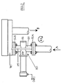
- FIG. 2 shows a side view of the measuring cell 50 in the circuit K2.
- a pipe section 60 is inserted into the pipeline forming the circuit K2 by means of flanges 56A, 56B, so that the polishing acid can flow into the measuring cell 50 in direction A, flow around the glass plate 55 and via an overflow box 70 back to the buffer tank 20 (arrow B) flows back.
- the measuring device of the measuring cell 50 is designed in the form of a tube, such that a radiation source 56 is arranged on one side of the tube piece 60, and a detector (scintillation counter) 57 on the opposite side for registering the ⁇ radiation penetrating the glass plate 55.
- the electrical signal of the scintillation counter is then fed to the control unit 40 for evaluation.
- FIG. 3 shows the pipe section 60 in longitudinal section.
- the pipe section 60 consists of at least one outer jacket and an inner pipe 61 (for example made of propylene), into which two diametrically opposite grooves 62, 63 are made.
- the appropriately dimensioned glass plate 55 can be inserted vertically like a drawer or slide, guided by the two grooves 62, 63, into the pipe section 60 until it sits on the lower end face of these grooves and is thus held.
- the outer wall of the tube section 60 also has windows F1, F2, which are diametrically opposite but offset by 90 ° with respect to the grooves 62, 63, which allow the passage of radioactive radiation, for example ⁇ radiation.
- a ⁇ radiation source 56 In front of the window F1 there is a ⁇ radiation source 56, with the actual radiator 56A (for example a 241 Am preparation), surrounded by a shield 56B and a collimator 56C.
- the dimensioning of the collimator 56C consequently defines a specific solid angle at which the ⁇ radiation of the radiation source 56A is emitted.
- the correspondingly larger window F2 on the opposite side of the pipe section 60 lies in front of the detection surface of the detector 57, for example a scintillation counter.
- the ⁇ radiation of the radiation source 56A therefore passes through the glass plate 55 and is registered by the detector 57.
- the registered count rate is consequently a measure of the absorption of the ⁇ radiation by the glass plate 55; accordingly, the change in count rate is a direct measure of the change in thickness of the glass plate 55, caused by the action of the polishing acid flowing past.
- Figure 4 shows a cross section through the pipe section 60 in the plane IV-IV of Figure 3, it can be seen that in the illustrated embodiment, the pipe section 60 is made of three layers, the inside forms the inner tube 61, in which the glass plate 55 is held, surrounded by the two-layer outer tube, which is made of polypropylene, for example.
Landscapes
- Chemical & Material Sciences (AREA)
- Engineering & Computer Science (AREA)
- Materials Engineering (AREA)
- Life Sciences & Earth Sciences (AREA)
- Chemical Kinetics & Catalysis (AREA)
- General Chemical & Material Sciences (AREA)
- Geochemistry & Mineralogy (AREA)
- Organic Chemistry (AREA)
- Automation & Control Theory (AREA)
- General Physics & Mathematics (AREA)
- Physics & Mathematics (AREA)
- Surface Treatment Of Glass (AREA)
- Finish Polishing, Edge Sharpening, And Grinding By Specific Grinding Devices (AREA)
Description
- Glas, insbesondere Hohlglas, wird nach der Bearbeitung zur Polierung oder Mattierung der Oberfläche in einem Säurebad bewegt. Die Polierflüssigkeit besteht im wesentlichen aus ca. 1 bis 10 Gew.-% Flußsäure (HF), 60 bis 70 Gew.-% Schwefelsäure (H2 SO4) und Wasser. Zum Polieren wird das zu polierende Gut in einen Polierbadbehälter gegeben. In das Polierbad wird aus dem Pufferbehälter mit der Pumpe P1 (s. Abb. 1) die Poliersäure gepumpt. Das zu polierende Material wird in dem Bad bewegt, um eine allseitig gleichmäßige Polierwirkung zu erzielen. Um Schmutzpartikel abzuspülen wird die Poliersäure in gewissen Zeitabständen abgelassen und das Bad mit Spülsäure gefüllt. Für eine Charge sind meist mehrere Polier- und Spülzyklen notwendig. Wenn der gewünschte Poliergrad erreicht ist, wird das Material entnommen und das Bad neu beschickt.
- Zum Spülen wird Schwefelsäure mit einer Konzentration von ca. 60 bis 70 Gew.-% verwendet, um eine Verdünnung des Polierbades durch Wasserverschleppung aus vorgeschalteten Wasserbädern zu vermeiden. Der Schwefelsäureanteil in der Poliersäure dient zur Überführung der durch die Flußsäure gelösten Glasbestandteile in Sulfate und unterstützt die Polierwirkung. Eine weitere Funktion ist die Bindung des durch vorgeschaltete Waschbäder mit dem Poliergut eingeschleppten Wassers, das sonst eine Verdünnung der Flußsäure bewirken würde. Für den Glasabtrag zur Glättung der Oberfläche ist der Flußsäureanteil wichtig. Die Länge der Polierzeit und das Ergebnis des Polierens wird insbesondere von diesem Anteil bestimmt. Zur Kontrolle der Flußsäurekonzentration werden aus dem Polierbadbehälter (meist einer rotierenden Trommel), während eines kurzen Stillstandes ein oder mehrere Teile entnommen. Ist das Ergebnis zufriedenstellend, wird der Poliervorgang beendet, andernfalls wird er fortgesetzt. Eine unzureichende Polierwirkung ist ein Zeichen für eine zu geringe Flußsäurekonzentration. Die Flußsäurekonzentration wird dann durch manuelle Zugabe von hochkonzentrierter Flußsäure wieder erhöht.
- Die Poliersäure weist eine Temperatur von ca. 60 bis 70 °C auf. Beim Öffnen der Trommel strömen sehr aggressive Säuredämpfe aus, die abgesaugt und neutralisiert werden müssen. Die Poliersäure selbst ist höchst aggressiv und verursacht schon in geringen Spuren Verätzungen der Haut. Ein Kontakt mit den Augen kann zur Erblindung führen. Die Gefahren und Belastungen für das Bedienungspersonal sind somit erheblich. Das führt bei manueller Handhabung dazu, daß meist zu großzügig Flußsäure zugegeben wird um ein Nachpolieren, wie es bei einem ungenügenden Polierergebnis notwendig wäre, zu vermeiden. Die Folgen sind erhöhter Flußsäureverbrauch, schwankende Polierzeiten, keine gleichbleibende Polierqualität, und ein erhöhter Anfall von Altsäure und dadurch eine Mehrbelastung der Abwasser- und Abluftneutralisation.
- Aus den genannten Gründen ist eine automatische Bestimmung und Regelung der Säurekonzentration äußerst wünschenswert.
- Der Schwefelsäureanteil läßt sich mit ausreichender Genauigkeit mit einer radiometrischen Dichtemessung bestimmen. Die Konzentration der Schwefelsäure ist mit 60 bis 70 Gew.- % relativ hoch und die Dichteänderung / Gew.-% H2SO4 ebenfalls. Störend wirkt sich der kontinuierlich ansteigende Anteil von unlöslichen Schwebstoffen, die ebenfalls einen Beitrag zur Dichteanzeige liefern, aus. Die Betriebserfahrung hat jedoch gezeigt, daß dieser Anstieg sehr gleichmäßig erfolgt, so daß sich der dadurch ergebende Beitrag zur Dichteerhöhung leicht von dem Dichtemeßwert subtrahieren läßt. Das sich dadurch ergebende Meßergebnis wird in vielen Fällen zur Kontrolle der Schwefelsäurekonzentration herangezogen.
- Der Beitrag der Flußsäure zur Gesamtdichte ist wesentlich geringer. Die Dichteänderung / Gew.-% Konzentration ist nur ca. 1/4 von dem der Schwefelsäure. Bei einem Gemisch aus 65 Gew.-% H2SO4 und 5 Gew.-% HF werden ca. 97,5% der Dichteerhöhung gegenüber H2O durch den Schwefelsäureanteil und nur ca. 2,5% durch den Flußsäureanteil verursacht. Zur Bestimmung der Flußsäurekonzentration ist deshalb die Dichtemessung mit "zeitabhängiger Schwebstoffkorrektur" zu ungenau und deshalb nicht einsetzbar.
- Beim gattungsbildenden Verfahren nach der DE-29 32 608 C2 wird durch Vergleichsmessungen ein Regelwert gewonnen, der eine begrenzte Automatisierung der Flußsäurebestimmung und Regelung der Flußsäureangabe grundsätzlich ermöglicht. Die Messungen einer radioaktiv markierten Referenzprobe bei "optimalem Säuregemisch" und die späteren Messungen der Vergleichsmuster unter aktuellen Säurekonzentrationen führen zu radioaktiv verunreinigten, aggressiven, abgelösten Säureresten, die in doppelter Hinsicht nur aufwendig zu entsorgen sind.
- Es ist daher Aufgabe der Erfindung, das vorbekannte Verfahren insbesondere dahingehend zu verbessern, daß radioaktiver Abfall und die damit verbundenen Entsorgungsprobleme vermieden werden.
- Erfindungsgemäß wird diese Aufgabe durch das Verfahren nach dem kennzeichnenden Teil des Patentanspruchs 1 bzw. eine Vorrichtung nach dem Kennzeichen des Patentanspruchs 3 gelöst.
- Der Grundgedanke der Erfindung besteht darin, den Abtrag nicht vom radioaktiv markierten Vergleichsmuster zu messen, was zum radioaktiv verseuchten Abfall führt, sondern die Dickenänderung einer nicht markierten Glasplatte direkt mit einer externen Strahlenquelle zu bestimmen.
- Die hierzu verwendeten Komponenten sind mechanisch robust, zum Beispiel können zum Durchpumpen der Poliersäure durch die Kreisläufe nach einer vorteilhaften Ausgestaltung Kreiselpumpen verwendet werden, bei denen der Kreisel durch ein außerhalb des Pumpengehäuses erzeugtes Magnetfeld angetrieben wird, hierdurch werden Dichtungsprobleme vermieden.
- Radiometrische Messungen werden in Glashütten und Polierbetrieben auch seit langem als Füllstands- und Dichtemessungen eingesetzt und haben sich unter den dort herrschenden Einsatzbedingungen, die vergleichbar mit den hier herrschenden Einsatzbedingungen sind, bestens bewährt.
- Die eingesetzten Komponenten, insbesondere die Meßeinrichtung kann unmittelbar neben dem Pufferbehälter aufgebaut werden, dadurch ist gewährleistet, daß die Temperatur der Säure, der das Vergleichsmuster ausgesetzt ist, identisch ist mit der Temperatur der Säure bzw. des Säuregemisches im Polierbadbehälter. Selbst wenn bei einer eventuellen Störung der Heizungsanlage für den Pufferbehälter die Säuretemperatur absinken würde, wäre eine einwandfreie Funktion noch gewährleistet, da der Glasabtrag sowohl am Poliergut, als auch am Vergleichsmuster gleichermaßen verringert würde. Bei einer solchen Situation würde jedoch automatisch die Regelung veranlassen, daß die Säurekonzentration wieder so weit angehoben wird, bis der Istwert des Glasabtrages wieder den vorgegebenen Sollwert erreicht.
- Weitere Ausgestaltungen des erfindungsgemäßen Verfahrens und der erfindungsgemäßen Vorrichtung sind weiteren Unteransprüchen zu entnehmen.
- Ein Ausführungsbeispiel der erfindungsgemäßen Vorrichtung zur Durchführung des Verfahrens wird nun anhand von Zeichnungen näher erläutert, es zeigen:
- Figur 1:
- Ein Blockschaltbild der erfindungsgemäßen Vorrichtung,
- Figur 2:
- eine Seitenansicht einer bevorzugten Ausführungsform der Meßzelle, eingebaut im Kreislauf K2,
- Figur 3:
- einen Längsschnitt durch die Meßzelle der Fig. 2,
- Figur 4:
- einen Querschnitt durch das Rohrstück der Meßzelle in der Ebene IV-IV der Figur 3,
- Figur 5:
- Tabellen und Funktionen zur Erläuterung des erfindungsgemäßen Verfahrens.
- Die in Figur 1 schematisch anhand eines Blockschaltbildes dargestellte Vorrichtung beinhaltet einen Polierbadbehälter 10, einen Pufferbehälter 20 und einen Flußsäurebehälter 30. Mit Hilfe einer ersten Pumpe P1 wird zwischen dem Polierbadbehälter 10 und dem Pufferbehälter 20 ein erster Kreislauf K1 der unter der Arbeitstemperatur befindlichen Poliersäure etabliert, d.h. dem im Polierbadbehälter eingesetzten Säuregemisch, wobei als Poliermittel insbesondere Flußsäure in einer Konzentration von 1 Gew.-% bis 10 Gew.-% Verwendung findet, neben 60 Gew.-% bis 70 Gew.-% Schwefelsäure und Wasser.
- Im Polierbadbehälter wird in bekannter Art und Weise das zu polierende Glasstück bewegt, so daß nach Ablauf einer bestimmten Zeitspanne ein bestimmter Oberflächenabtrag durch die Einwirkung des Säuregemisches erzielt wird. Während dieses Vorganges reduziert sich in der Regel der Anteil der Flußsäure im Säuregemisch, so daß von Zeit zu Zeit konzentrierte Flußsäure aus dem Flußsäurebehälter 30 mittels einer Dosierpumpe DP nachgeführt werden muß. Von Bedeutung ist, daß die Temperatur und die Konzentration der Poliersäure im Polierbadbehälter 10 und dem Pufferbehälter 20 durch den Kreislauf K1 jederzeit übereinstimmen, so daß die im Pufferbehälter 20 befindliche Poliersäure repräsentativ ist für die im Polierbadbehälter 10 wirkende Poliersäure.
- Vom Pufferbehälter 20 geht ein zweiter Kreislauf K2 aus, bei dem mit Hilfe einer zweiten Pumpe P2 über eine Meßzelle 50 Poliersäure aus dem Pufferbehälter die Meßzelle 50 durchströmt, in der ein Vergleichsmuster einer Glasplatte sich befindet, das in seinen Materialeigenschaften dem aktuell zu behandelnden Glasmuster im Polierbadbehälter 10 entspricht. Die in der Meßzelle 50 ablaufenden Poliervorgänge am dortigen Vergleichsmuster infolge der Einwirkung der Poliersäure simulieren folglich die im Polierbadbehälter 10 herrschenden Verhältnisse dynamisch, d.h., der Zustand sowohl der Poliersäure als auch des Vergleichsmusters in der Meßzelle 50 entsprechen denen im Polierbadbehälter 10, wenn während der Einwirkungszeit der Poliersäure im Polierbadbehälter 10 die beiden Kreisläufe K1 und K2 aktiviert sind.
- Das Vergleichsmuster ist in der Meßzelle 50 so angeordnet, daß es einer Dickenmessung zugänglich ist; beim Ausführungsbeispiel befindet sich auf der einen Seite eine radioaktive Strahlenquelle, die senkrecht auf die Oberfläche des Vergleichsmusters einstrahlt und auf der gegenüberliegenden Seite ein geeigneter Detektor, z.B. ein Szintillationszähler, der die durchtretende Strahlung registiert und die entsprechenden Impulsraten I anzeigt.
- Der Meßzelle 50 ist eine Regeleinheit 40 zugeordnet, der diese Impulsraten I zugeführt werden. Aus dem Vergleich der aktuellen Zählraten I mit vorgegebenen Sollwerten oder vorgegebenen Eichkurven errechnet die Regeleinheit ein Stellsignal für die Dosierpumpe DP und steuert somit die Zugabe von konzentrierter Flußsäure aus dem Flußsäurebehälter 30 in den Kreislauf K1 und damit in den Polierbadbehälter 10.
- Die beschriebene Anordnung beruht auf folgenden Überlegungen, die ihren Niederschlag in dem erfindungsgemäßen Verfahren gefunden haben:
- Beim Durchpumpen der Poliersäure durch die Meßzelle 50 wird Glas vom Vergleichsmuster abgetragen. Dadurch vermindert sich die Dicke der Vergleichsmuster-Platte, wobei der Glasabtrag umso größer ist, je länger das Vergleichsmuster der Säure ausgesetzt ist und je höher die Säurekonzentration ist (diese Änderungen verlaufen sozusagen "synchron" mit den entsprechenden Änderungen im Polierbadbehälter 10, wie oben erläutert). Die Dicke des Vergleichsmusters und damit auch die Dicke der Glasplatte im Polierbadbehälter wird durch die Bestimmung der Absorption im beschriebenen Ausführungsbeispiel (auch eine Bestimmung durch Reflexion ist möglich) der von der Strahlenquelle emittierten Strahlung im Vergleichsmuster ermittelt. Die Strahlungsintensität wird dabei vor und nach dem Durchpumpen der Säure durch die Meßzelle 50 während einer vorgebbaren Zeitspanne T ermittelt. Ist die hierbei gemessene Zählratenänderung zu klein gegenüber einem vorgegebenen Sollwert, so bedeutet dies, daß die Dickenänderung des Vergleichsmusters zu gering und folglich (bei gleichen anderen Betriebsparametern) die Konzentration der Flußsäure im Polierbad zu gering ist. Die aus der Zählratendifferenz gewonnene Information kann dann zur Gewinnung des Stellsignals herangezogen werden, das der Dosierpumpe DP dann übermittelt wird, die unter Berücksichtigung von deren Betriebsparametern eine definierte Menge konzentrierter Flußsäure vom Flußsäurebehälter 30 in den Pufferbehälter 20 pumpt und somit die Flußsäurekonzentration im Kreislauf K1 auf einen Wert erhöht, von dem nach den vorliegenden Eichwerten und Sollwerten anzunehmen ist, daß er den Glasabtrag entsprechend erhöht.
- Zur Verdeutlichung sind in Figur 5 einige Meßtabellen und Eichkurven dargestellt, die durch Einwirkung von Poliersäure mit einer Anfangskonzentration von 2 Gew.-% Flußsäure auf eine 1,6 mm dicke Glasplatte während einer Einwirkdauer von jeweils 5 Minuten gemessen wurden. Nach diesen 5 Minuten (Figur 5A) wurde diese Glasplatte mit Hilfe eines Meßgerätes vom Typ "LB 379" der Firma EG & G Laboratorium Prof. Dr. Rudolf Berthold GmbH & Co. KG in Bad Wildbad gemessen, das mit einer 3700 MBq 241Am Strahlungsquelle bestückt war. Die vom zugehörigen Szintillationszähler auf der anderen Seite der Glasplatte registrierten Impulse wurden gezählt, die Ergebnisse einer solchen Messung sind tabellarisch in Figur 5A zusammengefaßt und in Figur 5B die daraus gewonnene Eichkurve dargestellt.
- Man erkennt aus Figur 5A, daß bei einer Polierbadtemperatur TA im Bereich zwischen 59 und 64°C während einer Gesamteinwirkungsdauer von 45 Minuten des Polierbades auf die Glasplatte die in Abständen von 5 Minuten gewonnenen Meßpunkte zu dem in Figur 5B dargestellten, innerhalb statistischer Schwankungen linearen Zusammenhang zwischen dem ln IO/I und der Einwirkungszeit T in Minuten führen. Da der Glasabtrag als solcher ebenfalls proportional zur Einwirkungszeit der Poliersäure ist, ergibt sich hieraus, daß die Messung der Absorption radioaktiver Strahlung (ln IO/I) ein geeignetes Mittel ist, den Glasabtrag durch die Poliersäure durch Messung der verbleibenden Glasdicke zu bestimmen. Legt man folgende Werte zugrunde:


- Figur 2 zeigt eine Seitenansicht der Meßzelle 50 im Kreislauf K2. In die den Kreislauf K2 bildende Rohrleitung ist ein Rohrstück 60 mittels Flansche 56A,56B eingesetzt, so daß die Poliersäure in Richtung A in die Meßzelle 50 einströmen kann, dabei die Glasplatte 55 umströmt und über einen Überlaufkasten 70 wieder zum Pufferbehälter 20 (Pfeil B) zurückströmt.
- Die Meßeinrichtung der Meßzelle 50 ist in Form eines Rohres ausgeführt, derart, daß auf der einen Seite des Rohrstückes 60 eine Strahlungsquelle 56 angeordnet ist, auf der gegenüberliegenden Seite ein Detektor (Szintillationszähler) 57 zur Registrierung der die Glasplatte 55 durchsetzenden γ-Strahlung.
- Das elektrische Signal des Szintillationszählers wird dann zur Auswertung der Regeleinheit 40 zugeleitet.
- Figur 3 zeigt das Rohrstück 60 im Längsschnitt. Das Rohrstück 60 besteht aus mindestens einem Außenmantel und einem Innenrohr 61 (beispielsweise aus Propylen), in das zwei diametral gegenüberliegende Nuten 62,63 eingebracht sind. Nach Abnahme des Deckels des Überlaufkastens 70 kann die entsprechend dimensionierte Glasplatte 55 vertikal schubladen- oder schlittenähnlich, geführt von den beiden Nuten 62,63, in das Rohrstück 60 eingelassen werden, bis sie auf der unteren Stirnfläche dieser Nuten aufsitzt und somit gehalten ist.
- Die Außenwandung des Rohr-stücks 60 weist ebenfalls diametral gegenüberliegend, jedoch um 90° gegenüber den Nuten 62,63 versetzt, Fenster F1,F2 auf, die den Durchgang radioaktiver Strahlung, beispielsweise γ-Strahlung, gestatten.
- Vor dem Fenster F1 befindet sich eine γ-Strahlenquelle 56, mit dem eigentlichen Strahler 56A (beispielsweise ein 241Am-Präparat), umgeben von einer Abschirmung 56B und einem Kollimator 56C. Die Dimensionierung des Kollimators 56C definiert folglich einen bestimmten Raumwinkel, unter dem die γ-Strahlung der Strahlenquelle 56A abgegeben wird. Das entsprechend größer ausgebildete Fenster F2 auf der gegenüberliegenden Seite des Rohrstückes 60 liegt vor der Nachweisfläche des Detektors 57, beispielsweise eines Szintillationszählers. Die γ-Strahlung der Strahlenquelle 56A tritt demnach durch die Glasplatte 55 und wird vom Detektor 57 registriert. Die registrierte Zählrate ist folglich ein Maß für die Absorption der γ-Strahlung durch die Glasplatte 55; dementsprechend ist die Zählratenänderung ein direktes Maß für die Dickenänderung der Glasplatte 55, hervorgerufen durch die Wirkung der vorbeiströmenden Poliersäure.
- Figur 4 zeigt einen Querschnitt durch das Rohrstück 60 in der Ebene IV-IV der Figur 3, man erkennt, daß beim dargestellten Ausführungsbeispiel das Rohrstück 60 dreilagig ausgeführt ist, die Innenseite bildet das Innenrohr 61, in dem die Glasplatte 55 gehalten ist, umgeben von dem zweischichtigen Außenrohr, das beispielsweise aus Polypropylen besteht.
Claims (12)
- Verfahren zum Polieren oder Mattieren von Glasflächen in einem Säurebad (Polierbad) mit Flußsäure als aktiver Komponente, mit Hilfe eines Vergleichsmusters, dessen Eigenschaften dem im Polierbad befindlichen Glas entspricht, und auf das die im Polierbad aktuell wirkende Flußsäure einwirkt, wobei die Abtragswirkung der Flußsäure auf das Vergleichsglasmuster gemessen (Referenzmessung) und mit Hilfe dieses Meßwertes und vorgegebenen Sollwerten die Säurekonzentration im Polierbad geregelt wird, dadurch gekennzeichnet, daß als Vergleichsmuster eine Glasplatte (55) verwendet wird, und daß zur Bestimmung der Abtragswirkung innerhalb einer vorgebbaren Zeitspanne (T) eine Dickenmessung am Anfang und Ende dieser Zeitspanne (T) durchgeführt wird.
- Verfahren nach Anspruch 1, gekennzeichnet durch folgende Verfahrungsschritte:a) Zur Referenzmessung wird das aktuell wirkende Säuregemisch in eine Meßzelle (50) mit der darin gehaltenen Glasplatte (55) gepumpt,b) nach der Einwirkung werden die Meßzelle (50) und die Glasplatte (55) gespült,c) die Meßzelle (50) wird entleert,d) die Dickenmessung wird durchgeführt.
- Verfahren nach Anspruch 1 oder 2, dadurch gekennzeichnet, daß die Dickenmessung radiometrisch erfolgt.
- Vorrichtung zur Durchführung des Verfahrens nach Anspruch 1, mit einem Polierbadbehälter (10), einer Pumpe (P1) zur Zuführung von konzentrierter Flußsäure aus einem Flußsäurebehälter (30), einer Regeleinheit (40) zur Steuerung der Zufuhr konzentrierter Flußsäure aus dem Flußsäurebehälter (30) und einem Detektor (57) zur Gewinnung eines Meßwertes zur Eingabe in die Regeleinheit (40), dadurch gekennzeichnet, daß dem Polierbadbehälter (10) über einen ersten Kreislauf (K1) ein Pufferbehälter (20) zugeordnet ist, derart, daß das im Polierbadbehälter (10) aktuell wirkende Säuregemisch (Poliersäure) auch im Pufferbehälter (20) vorhanden ist, daß die Meßzelle (50) über einen zweiten Kreislauf (K2) vom Pufferbehälter (20) beschickbar ist, und daß an der Meßzelle (50) eine Meßeinrichtung mit dem Detektor (57) zur Dickenmessung angeordnet ist.
- Vorrichtung nach Anspruch 3, dadurch gekennzeichnet, daß die in den Kreisläufen (K1,K2) verwendeten Pumpen (P1,P2) magnetfeldbetriebene Kreiselpumpen sind.
- Vorrichtung nach Anspruch 4, dadurch gekennzeichnet, daß die Meßeinrichtung eine γ-Strahlenquelle (56) beinhaltet, deren Intensität nach Passieren der Glasplatte (55) der Detektor (57) mißt.
- Vorrichtung nach Anspruch 6, dadurch gekennzeichnet, daß die γ-Strahlenquelle (56) ein 241 Am-Präparat ist.
- Vorrichtung nach Anspruch 6, dadurch gekennzeichnet, daß die γ-Strahlenquelle (56) ein 244 Cm-Präparat ist.
- Vorrichtung nach Anspruch 4, dadurch gekennzeichnet, daß die Meßeinrichtung eine Röntgenröhre beinhaltet.
- Vorrichtung nach Anspruch 6, dadurch gekennzeichnet, daß die Meßeinrichtung ein Rohrstück (60) beinhaltet, in das die Glasplatte (55) axial einschiebbar ist, derart, daß sie im Strahlengang zwischen γ-Strahlenquelle (56) und Detektor (57) gehalten ist.
- Vorrichtung nach Anspruch 10, dadurch gekennzeichnet, daß die γ-Strahlenquelle (56) und Detektor (57) beidseitig des Rohrstückes (60) derart angeordnet sind, daß der Strahlengang im wesentlichen senkrecht zur Glasplatte (55) verläuft.
- Vorrichtung nach Anspruch 10, dadurch gekennzeichnet, daß das Rohrstück (60) ein Innenrohr (61) mit zwei gegenüberliegenden, axial verlaufenden Nuten (62,63) aufweist, in das die Glasplatte (55) schlittenartig einschiebbar ist.
Applications Claiming Priority (2)
| Application Number | Priority Date | Filing Date | Title |
|---|---|---|---|
| DE4405278 | 1994-02-19 | ||
| DE4405278A DE4405278C1 (de) | 1994-02-19 | 1994-02-19 | Verfahren und Vorrichtung zum Polieren oder Mattieren von Glasflächen in einem Säurebad |
Publications (2)
| Publication Number | Publication Date |
|---|---|
| EP0668251A1 EP0668251A1 (de) | 1995-08-23 |
| EP0668251B1 true EP0668251B1 (de) | 1997-01-15 |
Family
ID=6510615
Family Applications (1)
| Application Number | Title | Priority Date | Filing Date |
|---|---|---|---|
| EP95101442A Expired - Lifetime EP0668251B1 (de) | 1994-02-19 | 1995-02-03 | Verfahren und Vorrichtung zum Polieren oder Mattieren von Glasflächen in einem Polierbad |
Country Status (3)
| Country | Link |
|---|---|
| EP (1) | EP0668251B1 (de) |
| AT (1) | ATE147713T1 (de) |
| DE (1) | DE4405278C1 (de) |
Families Citing this family (1)
| Publication number | Priority date | Publication date | Assignee | Title |
|---|---|---|---|---|
| KR101233687B1 (ko) * | 2010-10-28 | 2013-02-15 | 삼성디스플레이 주식회사 | 유리 기판 식각 장치 |
Family Cites Families (1)
| Publication number | Priority date | Publication date | Assignee | Title |
|---|---|---|---|---|
| DE2932608C2 (de) * | 1979-08-10 | 1984-04-19 | Üvegipari Müvek, Budapest | Verfahren zum Polieren von geschliffenen Glasflächen |
-
1994
- 1994-02-19 DE DE4405278A patent/DE4405278C1/de not_active Expired - Fee Related
-
1995
- 1995-02-03 EP EP95101442A patent/EP0668251B1/de not_active Expired - Lifetime
- 1995-02-03 AT AT95101442T patent/ATE147713T1/de not_active IP Right Cessation
Also Published As
| Publication number | Publication date |
|---|---|
| EP0668251A1 (de) | 1995-08-23 |
| ATE147713T1 (de) | 1997-02-15 |
| DE4405278C1 (de) | 1995-05-04 |
Similar Documents
| Publication | Publication Date | Title |
|---|---|---|
| DE3787397T2 (de) | Verfahren zur Messung der Konzentrationen von Unreinheiten in einer Flüssigkeit und Vorrichtung dazu. | |
| DE19806559B4 (de) | Verfahren und Vorrichtung zur Behandlung von Geschirr in Spülmaschinen | |
| DE69414429T2 (de) | Szintillationszähler | |
| DE19936693A1 (de) | Verfahren zur ampereometrischen Bestimmung der Konzentration einer Substanz in einer Flüssigkeit | |
| DE2421649A1 (de) | Vorrichtung zur pruefung einer probe oder eines materials durch messung der absorption der gamma- oder roentgenstrahlung | |
| DE3110803A1 (de) | Automatisches analysiergeraet | |
| EP0361310A2 (de) | Messvorrichtung zur Bestimmung der Aktivität oder der Konzentration von Ionen in Lösungen | |
| DE2557872A1 (de) | Einrichtung zum messen des reflexionsvermoegens von reaktionsproben und mehrteilige probe dafuer | |
| DE60213940T2 (de) | Proben-Einführungssystem | |
| DE2718330B2 (de) | Blutanalysegerät | |
| DE10156809B4 (de) | Verfahren und Vorrichtung zur Blutzuckermessung | |
| DE10322143A1 (de) | Durchleuchtungsanlage und Verfahren zum Ermitteln der effektiven Hauteingangsdosis bei Durchleuchtungsuntersuchungen | |
| DE2220204B1 (de) | Photometer zur digitalen anzeige der konzentration einer messprobe in einer kuevette | |
| EP3578956B1 (de) | Verfahren und messvorrichtung zum bestimmen einer peressigsäure-konzentration in einem peressigsäure- und wasserstoffperoxidhaltigen sterilisierungsmedium | |
| DE2050672A1 (de) | Durchströmungskammer zur optischen Messung von Teilcheneigenschaften | |
| DE4405278C1 (de) | Verfahren und Vorrichtung zum Polieren oder Mattieren von Glasflächen in einem Säurebad | |
| EP0425809B1 (de) | Verfahren zum Bestimmen des Permeationsverhaltens | |
| DE1598528B1 (de) | Vorrichtung zur radiometrischen Analyse von Suspensionen | |
| DE1598120B2 (de) | Vorrichtung zur bestimmung des flaechenanteils verschiedener phasen auf oberflaechen heterogen aufgebauter metallischer oder nichtmetallischer stoffe | |
| EP0634645A1 (de) | Verfahren und Vorrichtung zum optischen Bestimmen von Feststoff-Konzentrationen in Wasser | |
| DE2946003A1 (de) | Verfahren zum kompensieren der an radioaktiven proben erhaltenen strahlungsmesswerte | |
| AT526372B1 (de) | Verfahren zur Bestimmung einer Verschmutzung | |
| DE2812995A1 (de) | Rueckstreuungsmessvorrichtung zur dickenmessung an einer schicht | |
| DE102007052520B4 (de) | Messsystem und Messverfahren zur Kontrolle und/oder Steuerung einer Wasseraufbereitung, insbesondere in einem Schwimmbad | |
| DE2914290C2 (de) | Verfahren zur kontrollierten chemischen Ausfällung von Fremdstoffen aus einem Strom wässriger Flüssigkeit und Vorrichtung zur Durchführung des Verfahrens |
Legal Events
| Date | Code | Title | Description |
|---|---|---|---|
| PUAI | Public reference made under article 153(3) epc to a published international application that has entered the european phase |
Free format text: ORIGINAL CODE: 0009012 |
|
| AK | Designated contracting states |
Kind code of ref document: A1 Designated state(s): AT FR GB IE |
|
| 17P | Request for examination filed |
Effective date: 19960223 |
|
| GRAG | Despatch of communication of intention to grant |
Free format text: ORIGINAL CODE: EPIDOS AGRA |
|
| 17Q | First examination report despatched |
Effective date: 19960515 |
|
| GRAH | Despatch of communication of intention to grant a patent |
Free format text: ORIGINAL CODE: EPIDOS IGRA |
|
| GRAH | Despatch of communication of intention to grant a patent |
Free format text: ORIGINAL CODE: EPIDOS IGRA |
|
| GRAA | (expected) grant |
Free format text: ORIGINAL CODE: 0009210 |
|
| AK | Designated contracting states |
Kind code of ref document: B1 Designated state(s): AT FR GB IE |
|
| REF | Corresponds to: |
Ref document number: 147713 Country of ref document: AT Date of ref document: 19970215 Kind code of ref document: T |
|
| REG | Reference to a national code |
Ref country code: IE Ref legal event code: FG4D Free format text: 71611 |
|
| GBT | Gb: translation of ep patent filed (gb section 77(6)(a)/1977) |
Effective date: 19970306 |
|
| ET | Fr: translation filed | ||
| PLBE | No opposition filed within time limit |
Free format text: ORIGINAL CODE: 0009261 |
|
| STAA | Information on the status of an ep patent application or granted ep patent |
Free format text: STATUS: NO OPPOSITION FILED WITHIN TIME LIMIT |
|
| 26N | No opposition filed | ||
| PGFP | Annual fee paid to national office [announced via postgrant information from national office to epo] |
Ref country code: FR Payment date: 20010215 Year of fee payment: 7 |
|
| PGFP | Annual fee paid to national office [announced via postgrant information from national office to epo] |
Ref country code: AT Payment date: 20010221 Year of fee payment: 7 |
|
| PGFP | Annual fee paid to national office [announced via postgrant information from national office to epo] |
Ref country code: IE Payment date: 20010222 Year of fee payment: 7 |
|
| REG | Reference to a national code |
Ref country code: GB Ref legal event code: IF02 |
|
| PGFP | Annual fee paid to national office [announced via postgrant information from national office to epo] |
Ref country code: GB Payment date: 20020110 Year of fee payment: 8 |
|
| PG25 | Lapsed in a contracting state [announced via postgrant information from national office to epo] |
Ref country code: AT Free format text: LAPSE BECAUSE OF NON-PAYMENT OF DUE FEES Effective date: 20020203 |
|
| PG25 | Lapsed in a contracting state [announced via postgrant information from national office to epo] |
Ref country code: IE Free format text: LAPSE BECAUSE OF NON-PAYMENT OF DUE FEES Effective date: 20020204 |
|
| PG25 | Lapsed in a contracting state [announced via postgrant information from national office to epo] |
Ref country code: FR Free format text: LAPSE BECAUSE OF NON-PAYMENT OF DUE FEES Effective date: 20021031 |
|
| REG | Reference to a national code |
Ref country code: FR Ref legal event code: ST |
|
| REG | Reference to a national code |
Ref country code: IE Ref legal event code: MM4A |
|
| PG25 | Lapsed in a contracting state [announced via postgrant information from national office to epo] |
Ref country code: GB Free format text: LAPSE BECAUSE OF NON-PAYMENT OF DUE FEES Effective date: 20030203 |
|
| GBPC | Gb: european patent ceased through non-payment of renewal fee |