EP0668132A1 - Verfahren und Vorrichtung zur Entfernung von Abfällen in einer Säge - Google Patents
Verfahren und Vorrichtung zur Entfernung von Abfällen in einer Säge Download PDFInfo
- Publication number
- EP0668132A1 EP0668132A1 EP95101794A EP95101794A EP0668132A1 EP 0668132 A1 EP0668132 A1 EP 0668132A1 EP 95101794 A EP95101794 A EP 95101794A EP 95101794 A EP95101794 A EP 95101794A EP 0668132 A1 EP0668132 A1 EP 0668132A1
- Authority
- EP
- European Patent Office
- Prior art keywords
- trim
- product
- products
- elongated
- adjacent
- Prior art date
- Legal status (The legal status is an assumption and is not a legal conclusion. Google has not performed a legal analysis and makes no representation as to the accuracy of the status listed.)
- Granted
Links
Images


Classifications
-
- B—PERFORMING OPERATIONS; TRANSPORTING
- B26—HAND CUTTING TOOLS; CUTTING; SEVERING
- B26D—CUTTING; DETAILS COMMON TO MACHINES FOR PERFORATING, PUNCHING, CUTTING-OUT, STAMPING-OUT OR SEVERING
- B26D7/00—Details of apparatus for cutting, cutting-out, stamping-out, punching, perforating, or severing by means other than cutting
- B26D7/18—Means for removing cut-out material or waste
- B26D7/1845—Means for removing cut-out material or waste by non mechanical means
- B26D7/1854—Means for removing cut-out material or waste by non mechanical means by air under pressure
-
- B—PERFORMING OPERATIONS; TRANSPORTING
- B26—HAND CUTTING TOOLS; CUTTING; SEVERING
- B26D—CUTTING; DETAILS COMMON TO MACHINES FOR PERFORATING, PUNCHING, CUTTING-OUT, STAMPING-OUT OR SEVERING
- B26D7/00—Details of apparatus for cutting, cutting-out, stamping-out, punching, perforating, or severing by means other than cutting
- B26D7/18—Means for removing cut-out material or waste
- B26D7/1845—Means for removing cut-out material or waste by non mechanical means
- B26D7/1863—Means for removing cut-out material or waste by non mechanical means by suction
-
- B—PERFORMING OPERATIONS; TRANSPORTING
- B26—HAND CUTTING TOOLS; CUTTING; SEVERING
- B26D—CUTTING; DETAILS COMMON TO MACHINES FOR PERFORATING, PUNCHING, CUTTING-OUT, STAMPING-OUT OR SEVERING
- B26D2210/00—Machines or methods used for cutting special materials
- B26D2210/11—Machines or methods used for cutting special materials for cutting web rolls
Definitions
- This invention relates to a trim eliminator for a saw and method and, more particularly, to a trim eliminator for a saw which transversely severs multi-ply material such as logs of bathroom tissue and kitchen toweling and bolts of folded facial tissue and toweling.
- a trim eliminator is intended to transport cut product from a saw conveyor, through the saw enclosure, and onto a conveyor system which eventually feeds some sort of packaging equipment.
- the saw conveyor is that which conveys the product through the cutting process.
- the log (rolled product) or bolt (folded product) has excess product (referred to as trim) at each end which is waste and must be discarded or recycled.
- jumbo sized parent rolls from a paper machine are transferred to a converting area where they are "rewound".
- the rewinding involves unwinding the parent rolls, usually transversely perforating the web therefrom, and then rewinding the web into a log having the diameter of a retail sized roll.
- Illustrative rewinders are co-owned U.S. Patents RE. 28,353 and 4,828,195 dealing respectively with the center winding type and the surface winding type of rewinder.
- the output of these machines normally is a log having a length equal to the width of the web being unwound from the parent roll.
- this log is subjected to transverse cutting by a log saw so as to develop a plurality of retail sized rolls and two end trim annuli.
- a log saw is co-owned U.S. Patent RE. 30,598.
- the annuli at the log ends are necessarily present because the width of the sheet or web from the parent roll cannot be exactly an even multiple of the number of rolls to be derived therefrom.
- a certain amount of "trim" is always provided so as to make sure that the end rolls, i.e., the rolls from each side of the web, have clean, flat ends.
- bolts as contrasted to logs are made up of multi-ply web material.
- Exemplary of machines for interfolding are those shown and described in co-owned U.S. patents 3,195,882 and 3,572,681.
- the trim pieces have been disposed of in a number of ways -- usually by supporting the roll or bolt piece and allowing the trim pieces to fall by gravity.
- the trim As the trim enters the area of the trim eliminator, it is not transported to the downstream conveying system. It is allowed to drop, thus eliminated. Once dropped, the trim must be removed from the saw enclosure by a separate means, such as a flat belt conveyor or a vacuum system.
- a separate means such as a flat belt conveyor or a vacuum system.
- Some examples of present trim eliminator conveying systems are: mechanical gripper fingers -- positioned above the product as in co-owned U.S. patent 4,977,803; round belt conveyor -- below product; single or dual vacuum belt -- above product; and side compression pad, mounted on chain conveyor, and slide bar -- positioned on side of product.
- the invention provides a method and apparatus for handling elongated lengths of multi-ply material and trim pieces resulting from transversely severing the elongated lengths to form shorter length products wherein each elongated length as well as the products therefrom has an upstream and a downstream end. And there are trim pieces at each end of each elongated length. Both the elongated lengths and then the shorter products are supportably advanced along a generally horizontally extending path with the invention including the steps of gripping and advancing the most upstream product of each elongated length while removing by generally upward movement the trim piece adjacent said most upstream product, and also removing by movement generally upwardly the trim piece adjacent the most downstream product.
- the removal steps are accomplished by applying an upwardly directed air blast below the trim pieces to move the trim pieces upwardly into a removal tube.
- the removal tube may be equipped with vacuum to develop or assist the upward movement of the trim pieces.
- a carriage For gripping, i.e., blocking upward movement, of the product adjacent a trim piece, a carriage is provided for each end of the elongated length, i.e., over the most upstream product and most downstream product.
- This carriage is positioned between the removal tube and the product to move with the product to ensure that it is not removed by the upward air flow.
- one carriage is equipped with gripper means and accelerates to the speed of the product, grabs the last cut product and moves it away from the trailing trim and product pusher. As the carriage moves, it allows the air flow to remove the trailing trim from the product area.
- Control of each carriage can be servo (motor, air, or hydraulic cylinder), mechanical means (cam and lever), air cylinder with proportional valve, stepper motor, etc.
- This invention is unique in that it combines the duties of the trim eliminator and trim removal systems. It provides a means to eliminate and remove the trim just after cutting while this product is still on the saw conveyor. This is compared to a transfer of the product to a trim eliminator in order to achieve trim elimination, then removal.
- the invention is simpler in that it does not handle each cut product -- only the first and last product of each log or bolt. This equates to less product marking and less maintenance.
- the invention offers a means to provide quick change or pushbutton change for cutoff length, log diameter or bolt height, log or bolt length and trim length.
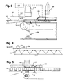
- the numeral 30 designates generally the frame of the saw apparatus.
- the numeral 31 designates generally the conveyor for the log or bolt to be transversely severed.
- the conveyor 31 conventionally has stationary side rails defining troughs for the product or work piece.
- These products are advanced along the horizontal path P (see the right hand portion of FIG. 1) by pushers 32 and 33 -- see FIG. 2.
- This showing is taken from U.S. Patent 4,977,803 where the left hand showing (here pusher 32) was of the then prior art and the right hand showing was of the new pusher (here 33) first disclosed in the '803 patent.
- the old style pushers 32 are employed.
- the numeral 34 designates a saw enclosure for a high-speed, continuous motion saw generally designated 35 and featuring disc-type blades 36.
- a saw can be seen in previously-mentioned co-owned patent RE. 30,598.
- the invention is not limited to any particular type saw, only one that develops trim pieces from a longer log or bolt.
- the invention is applicable to intermittent operation saws such as that shown and described in co-owned U.S. Patent No. 3,213,731.
- grippers 37 which also can be seen in FIG. 2.
- the grippers 37 are arranged in pairs as at 37a and 37b for each trough and are suspended from cross bars 38 advanced by a conveyor featuring spaced apart chains -- one of which is designated 39 in FIG. 2.
- the numeral 40 designates generally a trim removal vacuum chute and the numeral 41 the downstream conveying system.
- the frame is seen fragmentarily as at 30 in FIG. 2 and the troughs at 42 and 43.
- Two troughs are normally employed so as to balance the transverse cutting forces.
- roll pickers or grippers as at 37. These grip the roll after cutting to transport it horizontally to the takeaway conveyor 41. These grippers operate at the point where the endless pusher chain passes around the tail sprocket which, in FIG. 2 is masked by the guard 44.
- the tail sprocket is schematically represented as at 45 in FIG. 1.
- the trim is air forced/drawn upwardly, so there is no need for an opening 46 (see the left hand portion of FIG. 1).
- trough defining rails continue as at 147 in FIG. 3. They extend into overlapping relation with the take-away conveyor 41. Upstream from the rails 147 in FIG. 3, the apparatus is generally the same as that depicted in FIG. 1.
- the saw is generally designated 35 and the disc blade 36.
- the grippers of this invention are designated 137 (see the left central portion of FIG. 3) as contrasted to the prior art grippers 37 as seen in FIG. 2.
- the removal tube 148 which is supported on the frame 30 and air blast nozzles or jets generally designated 149 below the path P. Also different in the invention is a controller 150 which controls the position of carriage mechanisms 151, 152 which may perform a blocking function relative to the removal tube 148. The controller also regulates the air blast 149 and, if present, any vacuum in the removal tube 148. So, broadly speaking, there are three modes of operation: use of jets alone, use of jets plus vacuum, and vacuum alone.
- the downstream carriage 151 When there is suitable control of the vacuum, meaning it can be turned on and off at the appropriate time, the downstream carriage 151 is not needed. But, grippers 137 are still needed to move the product, adjacent to the trim, away from the trim and pusher. If this is not done, the product will squeeze the trim against the pusher not allowing the vacuum to lift it away.
- the downstream carriage 151 is needed to restrain product from being lifted away.
- the upstream carriage 152 is needed to restrain the most downstream product even if the vacuum is controlled. This is because the vacuum must remain on long enough to ensure that the trim has been removed from the saw area. It is this additional time which allows the most downstream product to come under the influence of the vacuum.
- the numeral 153 designates the sawhead velocity profile. Because two blades 36 are employed, the profile is a rectified sine wave. However, only the relatively flat crest of the sine wave characterizes the blade movement during cutting.
- the numeral 154 designates the start of the cut and the numeral 155 the end of the cut.
- the numeral 156 designates the conveyor velocity profile which is a straight line, i.e., constant.
- the other line 157 represents the gripper velocity profile -- which is a speed higher than either the sawhead or conveyor velocity.
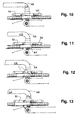
- FIG. 5 represents the condition of machine elements and product at the beginning of a trim disposal cycle.
- a cycle as starting with the trailing end annulus and finishing with the leading end annulus of the next log or elongated length of multi-ply web material.
- trailing trim carriage 151 begins to accelerate to match the velocity of the infeed conveyor 31.
- the air blast 149 is "off” and the leading trim carriage 152 is in its "DWELL” state.
- the product to the left is still being advanced by the pusher 42 -- but at a speed lower than that of the takeaway conveyor 41.
- the trailing trim carriage 151 has matched the speed of conveyor 31 and the gripper mechanism 137 pivots to its "grip" position to accelerate the product to the speed of conveyor 41.
- the time lapse between the showings of FIGS. 5 and 6 is fifty milliseconds.
- FIG. 7 is the showing of approximately one hundred fifty milliseconds after that of FIG. 5, i.e., one hundred fifty milliseconds into its cycle.
- the trailing trim carriage 151 is now at the velocity of the takeaway conveyor 41 and is starting to uncover the inlet to the removal tube 148 which may apply some suction to the product (if suction is employed), particularly the trailing trim T T which is being advanced by the pusher 42.
- FIG. 8 which is approximately three hundred fifty milliseconds from start, the conditions are as in FIG. 7 except for further advance of product and trim and the turning on of the air blast 149.
- the opening at the bottom of the removal tube 148 is substantially uncovered.
- the trailing trim T T is now well into the air tube 148.
- the leading trim carriage 152 begins its acceleration to slightly exceed the speed of the infeed conveyor 31.
- the trailing trim carriage 151 is seen in its forward DWELL position, having stopped and is about to accelerate rearwardly to return the upstream end of the carriage 151 to the forward edge of the removal tube 148 -- this condition being seen in FIG. 11 (six hundred fifty milliseconds and designated DWELL POSITION 2). Meanwhile the leading trim carriage 152 has reached its maximum velocity of slightly higher than that of the infeed conveyor 31. The air blast 149 is still on and the grippers 137' of the leading trim carriage 152 have pivoted to the grip position -- see FIG. 10.
- the leading trim T L is beginning to enter the removal tube 148 and in FIG. 13 (eight hundred fifty milliseconds) the trailing trim carriage 151 starts accelerating to return to its first DWELL position.
- the trailing trim carriage 151 is at DWELL, the air blast 149 is on and the leading trim carriage 152 is at maximum velocity (slightly faster than the velocity of the infeed conveyor 31).
- the trailing trim carriage 151 is still at DWELL.
- the leading trim carriage 152 now is at its maximum velocity which is slightly faster than the velocity of the infeed conveyor 31.
- the trailing trim carriage 151 is still at DWELL, the air blast is now off and the leading trim carriage 152 is at its maximum velocity which is slightly faster than that of the infeed conveyor.
- the trailing trim carriage 151 is still at DWELL. Now the leading trim carriage 152 begins to decelerate and the gripper 137' is pivoted off of the product. The trailing trim carriage 151 and leading trim carriage 153 now move together to the position shown in FIG. 5 in order to begin the next trim disposal cycle.
- FIG. 20 where the numeral 148 is in the center of the view and again designates the removal tube, i.e., the tube which draws the annuli away from the rails 147 (see the central part of FIG. 3).
- the annuli When the annuli are moved by the air blast 149, they can be delivered to a receptacle for repulping or other disposition.
- a separator such as a cyclone is normally interposed between the tube 148 and the receiver. Flanking the tube 148 in FIG. 20 are the trailing trim carriage 151 and the leading trim carriage 152.
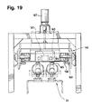
- carriages each are generally rectangular and at the four corners are equipped with guide wheels as at 158 relative to the carriage 151 and 159 relative to the carriage 152 (designated only in the lower left hand corners of each).
- the guide wheels 158 can be seen in FIG. 19 and are entrained on tracks as at 160 -- also designated in FIGS. 18 and 20.
- each of the carriages 151 and 152 is equipped with its own rotary actuator 161 and 162, respectively, for pivoting the grippers 137 and 137' into the raised and lowered positions.
- the raised position of the grippers 137 is seen in FIG. 5 and the lowered position in FIG. 6.
- the raised position of the grippers 137' is seen in FIG. 9 and the lowered position in FIG. 10.
- the rotary actuator can also be seen in the central portion of FIG. 19.
- a suitable device for this purpose can be obtained from Parker Fluid Power Co. located in Wadsworth, Ohio under product designation Rotary Actuator Model PV33D.
- the actuator has extended shafts as at 163 -- still referring to FIG.
- This element 165 may be of a soft, compressible foam which enables the element to conform to the contour of the shorter length product, i.e., bathroom tissue roll, interfolded facial tissue, etc.
- subframe 166 which carries the tracks 160 and therefore the carriages 151, 152.
- the subframe can be raised or lowered relative to the infeed conveyor generally designated 31 (see the lower central portion of FIG. 19) for changes in product, diameter and height.
- the subframe 166 is coupled to stepper motor means 167 -- see the upper central portion of FIG. 19 and also the upper left portion of FIG. 18.
- the upstream and downstream ends of the subframe 166 are stabilized by the bar and linkage assembly generally designated 168 and best seen in FIG. 18 in the upper portion of the view and extending from the left to the right end.
- the bar is designated 169 and the linkages 170 -- one at each end of the bar 169.
Applications Claiming Priority (4)
| Application Number | Priority Date | Filing Date | Title |
|---|---|---|---|
| US19876394A | 1994-02-18 | 1994-02-18 | |
| US198763 | 1994-02-18 | ||
| US34872494A | 1994-12-02 | 1994-12-02 | |
| US348724 | 1994-12-02 |
Publications (2)
| Publication Number | Publication Date |
|---|---|
| EP0668132A1 true EP0668132A1 (de) | 1995-08-23 |
| EP0668132B1 EP0668132B1 (de) | 1998-09-09 |
Family
ID=26894131
Family Applications (1)
| Application Number | Title | Priority Date | Filing Date |
|---|---|---|---|
| EP19950101794 Expired - Lifetime EP0668132B1 (de) | 1994-02-18 | 1995-02-09 | Verfahren und Vorrichtung zur Entfernung von Abfällen in einer Säge |
Country Status (4)
| Country | Link |
|---|---|
| EP (1) | EP0668132B1 (de) |
| CA (1) | CA2142081A1 (de) |
| DE (1) | DE69504545T2 (de) |
| ES (1) | ES2122354T3 (de) |
Cited By (6)
| Publication number | Priority date | Publication date | Assignee | Title |
|---|---|---|---|---|
| EP0995559A2 (de) * | 1998-10-19 | 2000-04-26 | Paper Converting Machine Company | Transportvorrichtung zur Handhabung von geschnittenen Produkten |
| EP1386701A1 (de) * | 2002-07-30 | 2004-02-04 | Giovanni Gambini | Vorrichtung zur Entfernung von Abfall von Rollen aus bahnartigem Material |
| US7946205B2 (en) * | 2003-12-12 | 2011-05-24 | Fabio Perini S.P.A. | Device and method for eliminating trimmings from series of products, such as rolls or the like |
| IT201600125579A1 (it) * | 2016-12-13 | 2018-06-13 | O M T S R L | Macchina per il taglio a misura di rotoli di prefissata lunghezza da bobine di lunghezza maggiore |
| WO2018109658A1 (en) * | 2016-12-13 | 2018-06-21 | O.M.T. S.R.L. | Machine for cutting to size rolls of predefined length from logs with a greater length |
| CN109531677A (zh) * | 2019-01-17 | 2019-03-29 | 精诚徽药药业股份有限公司 | 一种制药厂用转盘式切药装置 |
Citations (9)
| Publication number | Priority date | Publication date | Assignee | Title |
|---|---|---|---|---|
| US2020113A (en) * | 1933-07-08 | 1935-11-05 | John L Ferguson | Cutting machine |
| FR1304864A (fr) * | 1961-10-31 | 1962-09-28 | R C Can Co | Machine à fabriquer les tubes enroulés en hélice |
| FR2164382A5 (de) * | 1971-12-07 | 1973-07-27 | Skandinaviska Apparatind | |
| US4362461A (en) * | 1980-05-27 | 1982-12-07 | Ppg Industries, Inc. | Selective vacuum lifting device |
| GB2137918A (en) * | 1983-03-18 | 1984-10-17 | Lucchese Finanz | A Device for Removing Scrap |
| EP0468254A2 (de) * | 1990-07-21 | 1992-01-29 | Heidelberger Druckmaschinen Aktiengesellschaft | Querschneider für mit Druckbildern versehene Materialbahnen |
| DE4204756A1 (de) * | 1992-02-18 | 1993-05-13 | Wuestenberg Dieter Prof Dr Ing | Verfahren zur kontinuierlichen bzw. abschnittsweise kontinuierlichen raeumlichen trennung textiler gutteilstapel und dem sie umgebenden abfall |
| JPH0615599A (ja) * | 1992-07-04 | 1994-01-25 | Kawanoe Zoki Co Ltd | ロール紙のトリミング装置 |
| EP0607761A1 (de) * | 1992-09-28 | 1994-07-27 | FABIO PERINI S.p.A. | Vorrichtung zum Separierung von Abfall beim Schneiden von Papierrollen aus einer langen Stange |
-
1995
- 1995-02-08 CA CA 2142081 patent/CA2142081A1/en not_active Abandoned
- 1995-02-09 DE DE1995604545 patent/DE69504545T2/de not_active Expired - Fee Related
- 1995-02-09 ES ES95101794T patent/ES2122354T3/es not_active Expired - Lifetime
- 1995-02-09 EP EP19950101794 patent/EP0668132B1/de not_active Expired - Lifetime
Patent Citations (9)
| Publication number | Priority date | Publication date | Assignee | Title |
|---|---|---|---|---|
| US2020113A (en) * | 1933-07-08 | 1935-11-05 | John L Ferguson | Cutting machine |
| FR1304864A (fr) * | 1961-10-31 | 1962-09-28 | R C Can Co | Machine à fabriquer les tubes enroulés en hélice |
| FR2164382A5 (de) * | 1971-12-07 | 1973-07-27 | Skandinaviska Apparatind | |
| US4362461A (en) * | 1980-05-27 | 1982-12-07 | Ppg Industries, Inc. | Selective vacuum lifting device |
| GB2137918A (en) * | 1983-03-18 | 1984-10-17 | Lucchese Finanz | A Device for Removing Scrap |
| EP0468254A2 (de) * | 1990-07-21 | 1992-01-29 | Heidelberger Druckmaschinen Aktiengesellschaft | Querschneider für mit Druckbildern versehene Materialbahnen |
| DE4204756A1 (de) * | 1992-02-18 | 1993-05-13 | Wuestenberg Dieter Prof Dr Ing | Verfahren zur kontinuierlichen bzw. abschnittsweise kontinuierlichen raeumlichen trennung textiler gutteilstapel und dem sie umgebenden abfall |
| JPH0615599A (ja) * | 1992-07-04 | 1994-01-25 | Kawanoe Zoki Co Ltd | ロール紙のトリミング装置 |
| EP0607761A1 (de) * | 1992-09-28 | 1994-07-27 | FABIO PERINI S.p.A. | Vorrichtung zum Separierung von Abfall beim Schneiden von Papierrollen aus einer langen Stange |
Non-Patent Citations (1)
| Title |
|---|
| PATENT ABSTRACTS OF JAPAN vol. 18, no. 217 (M - 1594) 19 April 1994 (1994-04-19) * |
Cited By (9)
| Publication number | Priority date | Publication date | Assignee | Title |
|---|---|---|---|---|
| EP0995559A2 (de) * | 1998-10-19 | 2000-04-26 | Paper Converting Machine Company | Transportvorrichtung zur Handhabung von geschnittenen Produkten |
| EP0995559A3 (de) * | 1998-10-19 | 2002-08-07 | Paper Converting Machine Company | Transportvorrichtung zur Handhabung von geschnittenen Produkten |
| EP1386701A1 (de) * | 2002-07-30 | 2004-02-04 | Giovanni Gambini | Vorrichtung zur Entfernung von Abfall von Rollen aus bahnartigem Material |
| US7080738B2 (en) | 2002-07-30 | 2006-07-25 | Giovanni Gambini | Device for the elimination of trims of rolls or logs of sheeted material |
| US7946205B2 (en) * | 2003-12-12 | 2011-05-24 | Fabio Perini S.P.A. | Device and method for eliminating trimmings from series of products, such as rolls or the like |
| IT201600125579A1 (it) * | 2016-12-13 | 2018-06-13 | O M T S R L | Macchina per il taglio a misura di rotoli di prefissata lunghezza da bobine di lunghezza maggiore |
| WO2018109658A1 (en) * | 2016-12-13 | 2018-06-21 | O.M.T. S.R.L. | Machine for cutting to size rolls of predefined length from logs with a greater length |
| CN109531677A (zh) * | 2019-01-17 | 2019-03-29 | 精诚徽药药业股份有限公司 | 一种制药厂用转盘式切药装置 |
| CN109531677B (zh) * | 2019-01-17 | 2024-01-19 | 精诚徽药药业股份有限公司 | 一种制药厂用转盘式切药装置 |
Also Published As
| Publication number | Publication date |
|---|---|
| DE69504545D1 (de) | 1998-10-15 |
| EP0668132B1 (de) | 1998-09-09 |
| CA2142081A1 (en) | 1995-08-19 |
| ES2122354T3 (es) | 1998-12-16 |
| DE69504545T2 (de) | 1999-02-04 |
Similar Documents
| Publication | Publication Date | Title |
|---|---|---|
| US4966521A (en) | Tail stopping and knockdown device | |
| US5458033A (en) | Trim eliminator for log saw | |
| US5950510A (en) | Decelerating mechanism for printed products | |
| US5014582A (en) | Carton blank deceleration unit | |
| US7896329B2 (en) | Waste blower for a paper sheet punching and embossing machine | |
| US3883131A (en) | Delivery apparatus and method | |
| EP0116100A1 (de) | Apparat zum Aufnehmen, Verpacken und Weiterleiten von blattförmigem Material | |
| KR860001631B1 (ko) | 연속하여 흐르는 절단종이 시트를 감속하는 장치 및 방법 | |
| JPS6212577A (ja) | 無端の帯状材料をジグザグの形状に折りたたむための方法および装置 | |
| US4682767A (en) | Apparatus for folding and delivering sheet material | |
| JPS6142703B2 (de) | ||
| JPH0442313B2 (de) | ||
| US5829951A (en) | Collecting and stacking device for laminar sheets and stacking method | |
| EP0423272B1 (de) | Vorrichtung zum schneiden von zigarettenpackungen zwecks wiedergewinnung des tabaks in den zigaretten | |
| EP0668132B1 (de) | Verfahren und Vorrichtung zur Entfernung von Abfällen in einer Säge | |
| US4848059A (en) | Apparatus for packing a cylindrical stack of disk-like workpieces | |
| JPS62264168A (ja) | ウエブ材料の折りたたみ装置 | |
| US4977803A (en) | Saw mechanism for logs convolutely wound on cores and method | |
| US6883409B1 (en) | Device for cross/cutting material strips, in particular cardboard strips | |
| EP0995559B1 (de) | Transportvorrichtung zur Handhabung von geschnittenen Produkten | |
| EP2709807B1 (de) | Vorrichtung sowie verfahren zum entfernen von abfallteilen von einer reihe von produkten wie etwa rollen oder ähnlichem | |
| US4747591A (en) | Apparatus for separating folded perforated reel papers | |
| KR19980081283A (ko) | 절단 나이프에서 절단 시트들을 직접 싱글링하는 방법 및 장치 | |
| US5899403A (en) | Method and apparatus for winding bags onto a spindle | |
| CA1180260A (en) | Web splicing apparatus |
Legal Events
| Date | Code | Title | Description |
|---|---|---|---|
| PUAI | Public reference made under article 153(3) epc to a published international application that has entered the european phase |
Free format text: ORIGINAL CODE: 0009012 |
|
| AK | Designated contracting states |
Kind code of ref document: A1 Designated state(s): DE ES FR GB IT SE |
|
| 17P | Request for examination filed |
Effective date: 19960223 |
|
| 17Q | First examination report despatched |
Effective date: 19970401 |
|
| GRAG | Despatch of communication of intention to grant |
Free format text: ORIGINAL CODE: EPIDOS AGRA |
|
| GRAG | Despatch of communication of intention to grant |
Free format text: ORIGINAL CODE: EPIDOS AGRA |
|
| GRAH | Despatch of communication of intention to grant a patent |
Free format text: ORIGINAL CODE: EPIDOS IGRA |
|
| GRAH | Despatch of communication of intention to grant a patent |
Free format text: ORIGINAL CODE: EPIDOS IGRA |
|
| GRAA | (expected) grant |
Free format text: ORIGINAL CODE: 0009210 |
|
| AK | Designated contracting states |
Kind code of ref document: B1 Designated state(s): DE ES FR GB IT SE |
|
| REF | Corresponds to: |
Ref document number: 69504545 Country of ref document: DE Date of ref document: 19981015 |
|
| REG | Reference to a national code |
Ref country code: ES Ref legal event code: FG2A Ref document number: 2122354 Country of ref document: ES Kind code of ref document: T3 |
|
| ET | Fr: translation filed | ||
| PGFP | Annual fee paid to national office [announced via postgrant information from national office to epo] |
Ref country code: GB Payment date: 19990118 Year of fee payment: 5 |
|
| PGFP | Annual fee paid to national office [announced via postgrant information from national office to epo] |
Ref country code: FR Payment date: 19990128 Year of fee payment: 5 |
|
| PGFP | Annual fee paid to national office [announced via postgrant information from national office to epo] |
Ref country code: SE Payment date: 19990203 Year of fee payment: 5 |
|
| PGFP | Annual fee paid to national office [announced via postgrant information from national office to epo] |
Ref country code: DE Payment date: 19990206 Year of fee payment: 5 |
|
| PGFP | Annual fee paid to national office [announced via postgrant information from national office to epo] |
Ref country code: ES Payment date: 19990225 Year of fee payment: 5 |
|
| PLBE | No opposition filed within time limit |
Free format text: ORIGINAL CODE: 0009261 |
|
| STAA | Information on the status of an ep patent application or granted ep patent |
Free format text: STATUS: NO OPPOSITION FILED WITHIN TIME LIMIT |
|
| 26N | No opposition filed | ||
| PG25 | Lapsed in a contracting state [announced via postgrant information from national office to epo] |
Ref country code: GB Free format text: LAPSE BECAUSE OF NON-PAYMENT OF DUE FEES Effective date: 20000209 |
|
| PG25 | Lapsed in a contracting state [announced via postgrant information from national office to epo] |
Ref country code: SE Free format text: LAPSE BECAUSE OF NON-PAYMENT OF DUE FEES Effective date: 20000210 Ref country code: ES Free format text: LAPSE BECAUSE OF NON-PAYMENT OF DUE FEES Effective date: 20000210 |
|
| GBPC | Gb: european patent ceased through non-payment of renewal fee |
Effective date: 20000209 |
|
| EUG | Se: european patent has lapsed |
Ref document number: 95101794.6 |
|
| PG25 | Lapsed in a contracting state [announced via postgrant information from national office to epo] |
Ref country code: FR Free format text: LAPSE BECAUSE OF NON-PAYMENT OF DUE FEES Effective date: 20001031 |
|
| PG25 | Lapsed in a contracting state [announced via postgrant information from national office to epo] |
Ref country code: DE Free format text: LAPSE BECAUSE OF NON-PAYMENT OF DUE FEES Effective date: 20001201 |
|
| REG | Reference to a national code |
Ref country code: FR Ref legal event code: ST |
|
| REG | Reference to a national code |
Ref country code: ES Ref legal event code: FD2A Effective date: 20011010 |
|
| PG25 | Lapsed in a contracting state [announced via postgrant information from national office to epo] |
Ref country code: IT Free format text: LAPSE BECAUSE OF NON-PAYMENT OF DUE FEES Effective date: 20050209 |