EP0666366A1 - Tissu à hélices ayant une faible perméabilité et son procédé de fabrication - Google Patents
Tissu à hélices ayant une faible perméabilité et son procédé de fabrication Download PDFInfo
- Publication number
- EP0666366A1 EP0666366A1 EP95101482A EP95101482A EP0666366A1 EP 0666366 A1 EP0666366 A1 EP 0666366A1 EP 95101482 A EP95101482 A EP 95101482A EP 95101482 A EP95101482 A EP 95101482A EP 0666366 A1 EP0666366 A1 EP 0666366A1
- Authority
- EP
- European Patent Office
- Prior art keywords
- spiral
- spirals
- flat
- wires
- link belt
- Prior art date
- Legal status (The legal status is an assumption and is not a legal conclusion. Google has not performed a legal analysis and makes no representation as to the accuracy of the status listed.)
- Granted
Links
Images

Classifications
-
- D—TEXTILES; PAPER
- D21—PAPER-MAKING; PRODUCTION OF CELLULOSE
- D21F—PAPER-MAKING MACHINES; METHODS OF PRODUCING PAPER THEREON
- D21F1/00—Wet end of machines for making continuous webs of paper
- D21F1/0027—Screen-cloths
- D21F1/0072—Link belts
-
- Y—GENERAL TAGGING OF NEW TECHNOLOGICAL DEVELOPMENTS; GENERAL TAGGING OF CROSS-SECTIONAL TECHNOLOGIES SPANNING OVER SEVERAL SECTIONS OF THE IPC; TECHNICAL SUBJECTS COVERED BY FORMER USPC CROSS-REFERENCE ART COLLECTIONS [XRACs] AND DIGESTS
- Y10—TECHNICAL SUBJECTS COVERED BY FORMER USPC
- Y10S—TECHNICAL SUBJECTS COVERED BY FORMER USPC CROSS-REFERENCE ART COLLECTIONS [XRACs] AND DIGESTS
- Y10S162/00—Paper making and fiber liberation
- Y10S162/90—Papermaking press felts
-
- Y—GENERAL TAGGING OF NEW TECHNOLOGICAL DEVELOPMENTS; GENERAL TAGGING OF CROSS-SECTIONAL TECHNOLOGIES SPANNING OVER SEVERAL SECTIONS OF THE IPC; TECHNICAL SUBJECTS COVERED BY FORMER USPC CROSS-REFERENCE ART COLLECTIONS [XRACs] AND DIGESTS
- Y10—TECHNICAL SUBJECTS COVERED BY FORMER USPC
- Y10S—TECHNICAL SUBJECTS COVERED BY FORMER USPC CROSS-REFERENCE ART COLLECTIONS [XRACs] AND DIGESTS
- Y10S162/00—Paper making and fiber liberation
- Y10S162/902—Woven fabric for papermaking drier section
-
- Y—GENERAL TAGGING OF NEW TECHNOLOGICAL DEVELOPMENTS; GENERAL TAGGING OF CROSS-SECTIONAL TECHNOLOGIES SPANNING OVER SEVERAL SECTIONS OF THE IPC; TECHNICAL SUBJECTS COVERED BY FORMER USPC CROSS-REFERENCE ART COLLECTIONS [XRACs] AND DIGESTS
- Y10—TECHNICAL SUBJECTS COVERED BY FORMER USPC
- Y10T—TECHNICAL SUBJECTS COVERED BY FORMER US CLASSIFICATION
- Y10T428/00—Stock material or miscellaneous articles
- Y10T428/249921—Web or sheet containing structurally defined element or component
- Y10T428/249922—Embodying intertwined or helical component[s]
-
- Y—GENERAL TAGGING OF NEW TECHNOLOGICAL DEVELOPMENTS; GENERAL TAGGING OF CROSS-SECTIONAL TECHNOLOGIES SPANNING OVER SEVERAL SECTIONS OF THE IPC; TECHNICAL SUBJECTS COVERED BY FORMER USPC CROSS-REFERENCE ART COLLECTIONS [XRACs] AND DIGESTS
- Y10—TECHNICAL SUBJECTS COVERED BY FORMER USPC
- Y10T—TECHNICAL SUBJECTS COVERED BY FORMER US CLASSIFICATION
- Y10T428/00—Stock material or miscellaneous articles
- Y10T428/249921—Web or sheet containing structurally defined element or component
- Y10T428/249923—Including interlaminar mechanical fastener
Definitions
- the invention relates to a spiral link belt with a plurality of interconnected spirals, the turns of adjacent spirals being zippered together, so that the overlapping winding areas form a channel. Plug wires run in the channels so that the spirals cannot be separated. To reduce the air permeability of the spiral link belt, flat wires are inserted as filler material in the free space of the spirals.
- the invention further relates to a method for producing such a spiral link belt.
- Such spiral link belts are used in particular in the dryer section of high-speed paper machines. To achieve a low air permeability, it is necessary to fill the free interior of the spirals with filler material. If the air permeability is too high, the spiral link belt generates a very strong turbulent air flow, which can result in unsteady running and even breakage of the paper web. Spiral link belts currently in use still have an air permeability of at least 2280 m3 / m2 / hr / 100 Pa (CFM 140). This is too high for many applications.
- Spiral link belts in which the free space within the spirals is filled with filler material to reduce air permeability are known from EP-A-0 050 374 and EP-A-0 101 575.
- the filling material can consist of a ribbon yarn or a flat ribbon, among other things.
- Spiral link belts are produced in such a way that the spirals are first inserted into one another and then push-in wires are inserted into the channels which form the overlapping turns of adjacent spirals. If a spiral link belt with the lowest possible air permeability is to be produced, cored wires are then inserted into the free interior of the spirals. When using flat wires as cored wires, precautions must be taken to ensure that the flat wires do not twist. If several round wires are inserted as filling material in the interior of each spiral, it must be ensured that the round wires do not overlap. Twisting the flat wires or superimposing the round wires disturbs the monoplanarity of the finished spiral link belt, which can lead to markings in the paper web.
- This difficulty is usually countered by pre-fixing the spiral link belt before inserting the cored wires and flattening the originally slightly oval cross-sectional shape of the spirals by heat and pressure to such an extent that the flat wires and the multiple round wires can no longer twist or overlap. After inserting the cored wire, the spiral link belt is then finally heat set. The pre-fixation is therefore an additional step that causes considerable costs.
- the cored wires are also relatively loosely inside the spirals. Although the edges of a spiral link tape are glued, the lateral openings of the spirals are closed so that the cored wires cannot slip out laterally. However, the edges of a spiral link belt are often damaged when running in the paper machine and the cored wires are pulled out.
- the invention is therefore based on the object of providing a spiral link belt which has low air permeability with little production outlay.
- this object is achieved in that the flat wires, which are located as filling material in the interior of the spirals, are tilted relative to the plane of the spiral link belt.
- the tilting of the flat wires means that the longer cross-sectional axis of the flat wires lies at an angle to the longer cross-sectional axis of the spirals, which lies in the plane of the spiral link belt.
- the tilt angle can e.g. 15 to 25 ° and preferably about 20 °. The prerequisite for this is, of course, that the flat wire itself lies in one plane and is not twisted.
- the tilt angle is preferably so large that one edge of the flat wire lies above the plane of the highest points of the plug wires, while the other edge lies below the plane of the lowest points of the plug wires.
- the tilt angle can alternately be positive and negative, so that the flat wires, viewed in the axial direction of the spirals, alternately fall and rise from left to right.
- the flat wires running inside the spirals are preferably wider than the smallest distance between the two adjacent spirals connected to a respective spiral.
- the term "diagonal" refers to the imaginary square formed by the two and thus a total of four intersection points of a spiral with the preceding and the following spiral. Due to the larger width of the flat wires, they can no longer twist within the spiral.
- each spiral There is usually only one flat wire inside each spiral. However, there is also the possibility of inserting two flat wires of particularly low thickness, one on top of the other, into a spiral. However, each of these two particularly thin flat wires is then wider than the smallest distance between the two adjacent spirals connected to the respective spiral, as described above.
- a spiral link belt In order for a spiral link belt to have the lowest possible air permeability, it is not sufficient that it is essentially sealed by filling material, for example a flat wire, in plan view. There must also be no larger, three-dimensionally intertwined paths for air to pass through the spiral link belt. There is room for such a three-dimensionally intertwined path, in particular, between the tips of two adjacent turns of a spiral, since these two turns lie on one side of a plug-in wire, while the intermediate turn of the adjacent spiral lies on the other side of the plug-in wire, so that there is a passage opening , which is delimited laterally by the two winding arches and front and rear by the plug wire or the flat wire.
- the plug wire and the winding legs are similarly close together, so that there are no significant passage openings here either.
- a flat sawtooth or step-shaped surface which is largely closed, extends through the flat wires, the winding legs and arcs and the plug wires, viewed in the axial direction of the spirals.
- the spiral link belt according to the invention there are therefore no three-dimensionally intertwined paths of larger cross-section through the spiral link belt, so that it has a very low air permeability.
- spiral link belt Another advantage of the spiral link belt is that the flat wires are firmly anchored within the spiral link belt and therefore cannot be torn out of the spiral link belt even if the edges of the spiral link belt are damaged in the paper machine.
- the invention further relates to a method for producing the spiral link belt described above, the spiral link belt being heat set only once, namely after the insertion of the flat wires.
- the spiral link belt is heated and simultaneously in the longitudinal direction, i.e. in the plane of the spiral link belt perpendicular to the plug wires, stretched and flattened.
- the individual spirals are stretched and flattened.
- the flat wire inside a spiral turns towards the level of the sieve belt, i.e. the tilt angle becomes smaller, and the two longitudinal edges of the flat wire are pinched like scissors by the winding legs of the spiral in which it is located and by the winding arcs of the preceding or following spiral, so that the flat wire is firmly anchored in the screen structure and not from the Spiral can slip out.
- the apparent width of the flat wire increases parallel to the plane of the spiral link belt and presses the flat wire against the two adjacent spirals connected to the respective spiral, thereby filling in the gaps that still exist.
- Another advantage of the method according to the invention is that the plug wires and the flat wires serving as cored wires can be retracted at the same time.
- the spiral link belt can be made from spirals, the cross-sectional shape of which is a parallelogram with diagonals of different lengths, the plug wires inevitably sliding into the angles connected by the longer diagonals and the flat wires lying on the shorter diagonals.
- the corners of the parallelogram are of course rounded.
- Even wider flat wires can be inserted in spirals of this cross-sectional shape.
- the spiral link belt is heat-set after the flat wires have been retracted, the spirals then take on the usual flattened cross-sectional shape.
- the edges of each flat wire are at a greater depth between the winding legs the spiral in question and the winding arcs of the preceding or following spiral are clamped like scissors, which enables a further reduction in air permeability.
- the spirals can also be triangular, rectangular or square in cross-section or have any other cross-sectional shape into which particularly wide flat wires and in particular wider flat wires can be inserted than in the conventional oval spirals.
- the spirals can be wound from monofilaments with a circular cross-section. In order to achieve a particularly low air permeability, however, it is generally preferable to wind the spirals from monofilaments with a flattened cross section with an aspect ratio of approximately 1: 1.3 to 1: 3.
- edges of particularly wide flat wires can prevent the winding legs from lying in one plane at these points during heat-setting and thus the spiral link belt becoming monoplan. This difficulty can be remedied by using flat wires with tapered edges.
- the edges of such flat wires are more flexible because of the smaller material thickness and better fit around the winding legs and arches, from which they are pinched like scissors.
- the reduction in the material thickness preferably begins in the central region of the cross section of the flat wires, so that they have a flat diamond-shaped cross section.
- the flat wires can also have other cross-sectional profiles, for example the cross-sectional profile can only taper on one longitudinal edge, while it is just cut off or rounded on the other longitudinal edge.
- the cross-sectional profile can also be rounded on both longitudinal edges.
- flat wires are used which contract when they are heat-set in their longitudinal direction and expand in their transverse direction. So that the flat wires extend after the heat setting over the entire width of the spiral link belt, they are preferably inserted with a corresponding excess length in the cavities of the spirals.
- the flat wires therefore protrude slightly from the sides before heat setting. When heat setting, they then shrink in their longitudinal direction so that their final length corresponds to the width of the spiral link belt.
- the use of such flat wires has the advantage that the flat wires, due to their expansion in the transverse direction, fill the cavities of the spirals even better.
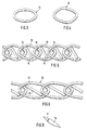
- Fig. 1 shows a spiral link belt in section in the longitudinal direction.
- the spiral link belt is composed of a multiplicity of spirals 10 which are located next to one another and engage in parallel, each spiral 10 being formed by a multiplicity of turns having an elliptical cross section.
- Each turn is divided into two turn arcs 11 and two winding legs 12 which are curved or flat to a lesser extent.
- the spirals 10 mesh with one another so that the turns 11 of a spiral 10 engage in a zipper-like manner with the turns 11 'and 11' 'of the two adjacent spirals 10' and 10 ''.
- This plug wires 14 are inserted, which firmly connect the spirals 11, 11 'and 11' 'so that the spirals can no longer be released from their mutual engagement.
- the winding legs 12 form the top and the bottom of the spiral link belt.
- the flat wires 15 are tilted with respect to the plane of the spiral link belt. As a result, more space is available for the flat wires 15 and can be wider Flat wires 15 are inserted into the spirals 10.
- the flat wire 15 within a spiral 10 runs approximately in the direction of the diagonal of the rectangle, which in FIG. 1 shows the intersection of the two winding arcs 11 of this spiral 10 with the overlapping winding arches 11 'and 11''of the neighboring spirals 10' and 10 '' is formed.
- FIG. 1 shows the spiral link belt before the heat setting, so that the spirals 11 have approximately their original elliptical or oval shape
- Fig. 2 shows the spiral link belt after the heat setting.
- the individual spirals 10 are flattened to such an extent that the winding legs 12 lie almost in one plane, and thus form a largely smooth surface of the spiral link belt.
- the tilt angle of the flat wires 15 is now smaller, it is still so large that the one in Fig. 1 left, longitudinal edge of the flat wire 15 lies above the plane defined by the highest points of the plug wires 14, while the other, in Fig. 1 right, longitudinal edge of the flat wire 15 is below the plane which is defined by the lowest points of the plug wires 14.
- the width of the flat wires 15 is selected such that it is larger than the smallest distance between the spirals 10 'and 10' ', which are connected to a spiral 10, even after the heat setting.
- the flat wires 15 are thereby clamped at their longitudinal edges like scissors between the turns 11 of a spiral and the interlocking turns 11 'and 11' 'of the preceding or the following spiral 10', 10 ''.
- Fig. 3 shows the usual oval cross-sectional shape of spirals, as used for the production of spiral link belts, before the heat setting.
- spirals with a parallelogram cross section according to FIG. 4 are used instead of the conventional oval cross section.
- the parallelogram has angles of approximately 50 ° and 130 ° and the aspect ratio the sides of the parallelogram are around 1.5 to 2.
- FIG. 5 shows in longitudinal section a section comprising a plurality of spirals from such a spiral link belt prior to heat setting.
- the plug wires 14 lie in the angles of the parallelogram connected by the longer diagonal, so that the position of the spirals 10 is stable during heat setting. 5, the position of the flat wires 15 coincides approximately with the shorter diagonal of the parallelogram.
- the previously mentioned flat wires have a rectangular cross section of, for example, 0.5 x 2.8 mm.
- the edges of the flat wires 15 are clamped like scissors between the winding arcs and legs 11, 12 during the heat setting.
- flat wires 15 become with them Longitudinal edges tapering cross-sectional profile used.
- the longitudinal edges are chamfered so that there is a cutting edge 16 parallel to the surface of the spiral link belt, ie the taper angle is approximately equal to the tilt angle of the flat wires.
- the air permeability is not affected by this, but the monoplanarity of the spiral link belt is preserved.
- Fig. 8 shows in section flat wires 15 with a cross-sectional profile that tapers at a particularly acute angle 17, so that the cross-sectional profile is almost diamond-shaped.
- the values given are the dimensions before the heat setting.
- the air permeability was of course measured after heat setting.
- the free distance between the adjacent spirals is calculated from the longer cross-sectional dimension of the spirals minus 4 x diameter of the spiral wire minus 2 x diameter of the plug wire. In all three cases, this distance is significantly smaller than the longer cross-sectional dimension of the filler flat wires. Of course, the relations shift somewhat due to the heat setting. Even after heat setting, the flat wires are still wider than the just defined distance of the neighboring spirals.
Landscapes
- Ropes Or Cables (AREA)
- Wire Processing (AREA)
- Shaping Of Tube Ends By Bending Or Straightening (AREA)
- Decoration Of Textiles (AREA)
- Footwear And Its Accessory, Manufacturing Method And Apparatuses (AREA)
- Winding Of Webs (AREA)
- Yarns And Mechanical Finishing Of Yarns Or Ropes (AREA)
- Treatment Of Fiber Materials (AREA)
Applications Claiming Priority (2)
| Application Number | Priority Date | Filing Date | Title |
|---|---|---|---|
| DE4403501 | 1994-02-04 | ||
| DE4403501A DE4403501A1 (de) | 1994-02-04 | 1994-02-04 | Spiralgliederband niedriger Luftdurchlässigkeit und Verfahren zu seiner Herstellung |
Publications (2)
| Publication Number | Publication Date |
|---|---|
| EP0666366A1 true EP0666366A1 (fr) | 1995-08-09 |
| EP0666366B1 EP0666366B1 (fr) | 1997-10-22 |
Family
ID=6509501
Family Applications (1)
| Application Number | Title | Priority Date | Filing Date |
|---|---|---|---|
| EP95101482A Expired - Lifetime EP0666366B1 (fr) | 1994-02-04 | 1995-02-03 | Tissu à hélices ayant une faible perméabilité et son procédé de fabrication |
Country Status (7)
| Country | Link |
|---|---|
| US (1) | US5514456A (fr) |
| EP (1) | EP0666366B1 (fr) |
| AT (1) | ATE159555T1 (fr) |
| BR (1) | BR9500435A (fr) |
| CA (1) | CA2141706C (fr) |
| DE (2) | DE4403501A1 (fr) |
| FI (1) | FI105938B (fr) |
Cited By (4)
| Publication number | Priority date | Publication date | Assignee | Title |
|---|---|---|---|---|
| WO2008122471A1 (fr) * | 2007-04-10 | 2008-10-16 | Voith Patent Gmbh | Tissu à faible perméabilité |
| WO2013004474A1 (fr) * | 2011-07-06 | 2013-01-10 | Württembergische Spiralsiebfabrik Gmbh | Structure plane thermiquement non fixée pour une toile en spirale et procédé de fabrication d'une toile en spirale |
| WO2014159400A1 (fr) * | 2013-03-14 | 2014-10-02 | Albany International Corp. | Bobine en forme d'infini pour coutures en spirale |
| WO2014159378A1 (fr) * | 2013-03-14 | 2014-10-02 | Albany International Corp. | Tissus industriels comprenant des enroulements en forme de leminscate |
Families Citing this family (15)
| Publication number | Priority date | Publication date | Assignee | Title |
|---|---|---|---|---|
| US6736714B2 (en) * | 1997-07-30 | 2004-05-18 | Praxair S.T. Technology, Inc. | Polishing silicon wafers |
| US6514301B1 (en) | 1998-06-02 | 2003-02-04 | Peripheral Products Inc. | Foam semiconductor polishing belts and pads |
| US7718102B2 (en) * | 1998-06-02 | 2010-05-18 | Praxair S.T. Technology, Inc. | Froth and method of producing froth |
| US6880583B2 (en) * | 2002-05-29 | 2005-04-19 | Albany International Corp. | Papermaker's and industrial fabric seam |
| US6918998B2 (en) * | 2002-11-13 | 2005-07-19 | Albany International Corp. | On-machine-seamable industrial fabric comprised of interconnected rings |
| CA2548396C (fr) * | 2003-12-15 | 2012-09-25 | Albany International Corp. | Pivot pour tissus en spirale |
| US7691238B2 (en) | 2004-12-15 | 2010-04-06 | Albany International Corp. | Spiral fabrics |
| US7575659B2 (en) * | 2004-12-15 | 2009-08-18 | Albany International Corp. | Spiral fabrics |
| US8640862B2 (en) * | 2006-04-10 | 2014-02-04 | Albany International Corp. | Seam-on laminated belt |
| US7604026B2 (en) * | 2006-12-15 | 2009-10-20 | Albany International Corp. | Triangular weft for TAD fabrics |
| US20080169039A1 (en) * | 2007-01-17 | 2008-07-17 | Mack Vines | Low permeability fabric |
| DE102007055759A1 (de) | 2007-12-11 | 2009-06-18 | Voith Patent Gmbh | Spiralgliederband |
| SE537959C2 (sv) | 2013-03-27 | 2015-12-08 | Valmet Aktiebolag | Rullstol och förfarande för upprullning av en pappersbana itorränden av en pappersmaskin |
| SE537744C2 (sv) * | 2013-04-26 | 2015-10-13 | Valmet Aktiebolag | Rullstol för upprullning av en pappersbana till en rulle ochförfarande för upprullning av en pappersbana för att bildaen rulle |
| WO2015034413A1 (fr) | 2013-09-09 | 2015-03-12 | Valmet Aktiebolag | Enrouleuse et procédé d'enroulement d'une bande de papier sous la forme d'un rouleau et de démarrage d'un nouveau rouleau |
Citations (6)
| Publication number | Priority date | Publication date | Assignee | Title |
|---|---|---|---|---|
| EP0050374A1 (fr) | 1980-10-22 | 1982-04-28 | SITEG Siebtechnik GmbH | Procédé de fabrication d'une bande de tamisage constituée de spirales bourrées en matière synthétique et bande de tamisage produite de cette manière |
| US4381612A (en) | 1981-06-03 | 1983-05-03 | Wangner Systems, Inc. | Dryer fabric for papermaking machine and method |
| EP0101575A2 (fr) | 1982-07-27 | 1984-02-29 | SITEG Siebtechnik GmbH | Bande à chaînons |
| EP0128496A2 (fr) * | 1983-06-08 | 1984-12-19 | Wangner Systems Corporation | Bande à chaînons à faible perméabilité et son procédé de fabrication |
| US4500590A (en) * | 1984-06-25 | 1985-02-19 | Wangner Systems Corporation | Dryer fabric having reduced permeability in the area of the pintle joint |
| GB2216914A (en) * | 1988-03-12 | 1989-10-18 | Scapa Group Plc | Link fabrics |
Family Cites Families (4)
| Publication number | Priority date | Publication date | Assignee | Title |
|---|---|---|---|---|
| GB1018419A (en) * | 1963-08-23 | 1966-01-26 | British Wedge Wire Company Ltd | Improvements in or relating to wire belts |
| DE3047989C2 (de) * | 1980-12-19 | 1984-11-15 | Reinhard Werner 6057 Dietzenbach Leo | Drahtwendel für die Herstellung eines flächigen Gliederbandes |
| DE4026196A1 (de) * | 1990-08-18 | 1992-02-20 | Heimbach Gmbh Thomas Josef | Sieb zur anwendung bei der papierfabrikation |
| DE4122805C1 (de) * | 1991-07-10 | 1994-10-06 | Heimbach Gmbh Thomas Josef | Drahtgliederband |
-
1994
- 1994-02-04 DE DE4403501A patent/DE4403501A1/de not_active Withdrawn
-
1995
- 1995-02-02 CA CA002141706A patent/CA2141706C/fr not_active Expired - Lifetime
- 1995-02-03 EP EP95101482A patent/EP0666366B1/fr not_active Expired - Lifetime
- 1995-02-03 AT AT95101482T patent/ATE159555T1/de active
- 1995-02-03 FI FI950500A patent/FI105938B/fi not_active IP Right Cessation
- 1995-02-03 BR BR9500435A patent/BR9500435A/pt not_active IP Right Cessation
- 1995-02-03 US US08/383,433 patent/US5514456A/en not_active Expired - Lifetime
- 1995-02-03 DE DE59500817T patent/DE59500817D1/de not_active Expired - Lifetime
Patent Citations (6)
| Publication number | Priority date | Publication date | Assignee | Title |
|---|---|---|---|---|
| EP0050374A1 (fr) | 1980-10-22 | 1982-04-28 | SITEG Siebtechnik GmbH | Procédé de fabrication d'une bande de tamisage constituée de spirales bourrées en matière synthétique et bande de tamisage produite de cette manière |
| US4381612A (en) | 1981-06-03 | 1983-05-03 | Wangner Systems, Inc. | Dryer fabric for papermaking machine and method |
| EP0101575A2 (fr) | 1982-07-27 | 1984-02-29 | SITEG Siebtechnik GmbH | Bande à chaînons |
| EP0128496A2 (fr) * | 1983-06-08 | 1984-12-19 | Wangner Systems Corporation | Bande à chaînons à faible perméabilité et son procédé de fabrication |
| US4500590A (en) * | 1984-06-25 | 1985-02-19 | Wangner Systems Corporation | Dryer fabric having reduced permeability in the area of the pintle joint |
| GB2216914A (en) * | 1988-03-12 | 1989-10-18 | Scapa Group Plc | Link fabrics |
Cited By (8)
| Publication number | Priority date | Publication date | Assignee | Title |
|---|---|---|---|---|
| WO2008122471A1 (fr) * | 2007-04-10 | 2008-10-16 | Voith Patent Gmbh | Tissu à faible perméabilité |
| WO2013004474A1 (fr) * | 2011-07-06 | 2013-01-10 | Württembergische Spiralsiebfabrik Gmbh | Structure plane thermiquement non fixée pour une toile en spirale et procédé de fabrication d'une toile en spirale |
| US9085852B2 (en) | 2011-07-06 | 2015-07-21 | Wuerttembergische Spiralsiebfabrik Gmbh | Non-thermoset sheet-like structure for a spiral sieve, and method for manufacturing a spiral sieve |
| WO2014159400A1 (fr) * | 2013-03-14 | 2014-10-02 | Albany International Corp. | Bobine en forme d'infini pour coutures en spirale |
| WO2014159378A1 (fr) * | 2013-03-14 | 2014-10-02 | Albany International Corp. | Tissus industriels comprenant des enroulements en forme de leminscate |
| US10689796B2 (en) | 2013-03-14 | 2020-06-23 | Albany International Corp. | Infinity shape coil for spiral seams |
| US10689807B2 (en) | 2013-03-14 | 2020-06-23 | Albany International Corp. | Industrial fabrics comprising infinity shape coils |
| US11619001B2 (en) | 2013-03-14 | 2023-04-04 | Albany International Corp. | Infinity shape coils for industrial fabrics |
Also Published As
| Publication number | Publication date |
|---|---|
| DE59500817D1 (de) | 1997-11-27 |
| US5514456A (en) | 1996-05-07 |
| ATE159555T1 (de) | 1997-11-15 |
| DE4403501A1 (de) | 1995-08-10 |
| FI105938B (fi) | 2000-10-31 |
| FI950500A0 (fi) | 1995-02-03 |
| EP0666366B1 (fr) | 1997-10-22 |
| BR9500435A (pt) | 1995-10-17 |
| CA2141706A1 (fr) | 1995-08-05 |
| FI950500A (fi) | 1995-08-05 |
| CA2141706C (fr) | 1998-11-24 |
Similar Documents
| Publication | Publication Date | Title |
|---|---|---|
| EP0666366B1 (fr) | Tissu à hélices ayant une faible perméabilité et son procédé de fabrication | |
| DE2930470C2 (fr) | ||
| DE3529418C1 (en) | Blind web of a slatted blind and method of manufacturing it | |
| DE102011084336A1 (de) | Gurtband und Verfahren zur Herstellung eines Gurtbands | |
| DE3709502A1 (de) | Netzbeutel aus extrudiertem kunststoffmaterial | |
| EP0080713B1 (fr) | Bande à chaînons et son procédé de fabrication | |
| EP2730688B1 (fr) | Lisse, de préférence pour le traitement d'un matériau en forme de bande, et son procédé de fabrication | |
| DE19641145C2 (de) | Selbstdichtendes Ventil für aufblasbare Körper und Verfahren zu seiner Herstellung und zum Einsetzen in den aufblasbaren Körper | |
| DE3638036A1 (de) | Spiralgliederband mit geteilten spiralen | |
| EP0112432B1 (fr) | Bande, notamment une bande de tamisage respectivement une bande à chaînons, pour machines à papier et similaires | |
| CH654361A5 (de) | Drahtgliederband. | |
| DE3102616A1 (de) | Isolierkoerper | |
| EP2729611B1 (fr) | Structure plane thermiquement non fixée pour une toile en spirale et procédé de fabrication d'une toile en spirale | |
| EP0054745B1 (fr) | Bande articulée plane | |
| CH637709A5 (en) | Profiled reed dent for a reed and use of the reed dent for the reed of a jet-weaving machine | |
| DE2039155A1 (de) | Armierung,insbesondere fuer Stahl- und Eisenbeton | |
| EP0190732A1 (fr) | Ruban articulé hélicoidal avec perméabilité réduite à l'air | |
| EP0196040A2 (fr) | Tissu en hélices combinées à perméabilité réduite et son procédé de fabrication | |
| WO1999064654A1 (fr) | Peigne et lamelle | |
| DE3534264A1 (de) | Spiralgliederband mit fuellspiralen, die um den steckdraht gewickelt sind | |
| DE2428215A1 (de) | Netz und verfahren zu seiner herstellung | |
| EP3636851B1 (fr) | Profilé d'enduit | |
| DE2947748C2 (de) | Verschweißter Fachwerkträger | |
| EP1370167A1 (fr) | Combinaison de bandes permettant de positionner des lattes dans un sommier a lattes | |
| AT400853B (de) | Sieb für papierzellstoff-splitterfänger und klassierer |
Legal Events
| Date | Code | Title | Description |
|---|---|---|---|
| PUAI | Public reference made under article 153(3) epc to a published international application that has entered the european phase |
Free format text: ORIGINAL CODE: 0009012 |
|
| AK | Designated contracting states |
Kind code of ref document: A1 Designated state(s): AT BE CH DE ES FR GB IT LI NL SE |
|
| 17P | Request for examination filed |
Effective date: 19950911 |
|
| GRAG | Despatch of communication of intention to grant |
Free format text: ORIGINAL CODE: EPIDOS AGRA |
|
| 17Q | First examination report despatched |
Effective date: 19961223 |
|
| GRAH | Despatch of communication of intention to grant a patent |
Free format text: ORIGINAL CODE: EPIDOS IGRA |
|
| GRAH | Despatch of communication of intention to grant a patent |
Free format text: ORIGINAL CODE: EPIDOS IGRA |
|
| GRAA | (expected) grant |
Free format text: ORIGINAL CODE: 0009210 |
|
| AK | Designated contracting states |
Kind code of ref document: B1 Designated state(s): AT BE CH DE ES FR GB IT LI NL SE |
|
| PG25 | Lapsed in a contracting state [announced via postgrant information from national office to epo] |
Ref country code: IT Free format text: LAPSE BECAUSE OF FAILURE TO SUBMIT A TRANSLATION OF THE DESCRIPTION OR TO PAY THE FEE WITHIN THE PRESCRIBED TIME-LIMIT;WARNING: LAPSES OF ITALIAN PATENTS WITH EFFECTIVE DATE BEFORE 2007 MAY HAVE OCCURRED AT ANY TIME BEFORE 2007. THE CORRECT EFFECTIVE DATE MAY BE DIFFERENT FROM THE ONE RECORDED. Effective date: 19971022 Ref country code: ES Free format text: THE PATENT HAS BEEN ANNULLED BY A DECISION OF A NATIONAL AUTHORITY Effective date: 19971022 |
|
| REF | Corresponds to: |
Ref document number: 159555 Country of ref document: AT Date of ref document: 19971115 Kind code of ref document: T |
|
| REG | Reference to a national code |
Ref country code: CH Ref legal event code: NV Representative=s name: RITSCHER & SEIFERT PATENTANWAELTE VSP Ref country code: CH Ref legal event code: EP |
|
| REF | Corresponds to: |
Ref document number: 59500817 Country of ref document: DE Date of ref document: 19971127 |
|
| GBT | Gb: translation of ep patent filed (gb section 77(6)(a)/1977) |
Effective date: 19971124 |
|
| ET | Fr: translation filed | ||
| PG25 | Lapsed in a contracting state [announced via postgrant information from national office to epo] |
Ref country code: BE Free format text: LAPSE BECAUSE OF NON-PAYMENT OF DUE FEES Effective date: 19980228 |
|
| PLBE | No opposition filed within time limit |
Free format text: ORIGINAL CODE: 0009261 |
|
| STAA | Information on the status of an ep patent application or granted ep patent |
Free format text: STATUS: NO OPPOSITION FILED WITHIN TIME LIMIT |
|
| BERE | Be: lapsed |
Owner name: SITEG SIEBTECHNIK G.M.B.H. Effective date: 19980228 |
|
| 26N | No opposition filed | ||
| REG | Reference to a national code |
Ref country code: CH Ref legal event code: PFA Free format text: SITEG SIEBTECHNIK GMBH TRANSFER- WUERTTEMBERGISCHE FILZTUCHFABRIK D. GESCHMAY GMBH |
|
| NLS | Nl: assignments of ep-patents |
Owner name: WUERTTEMBERGISCHE FILZTUCHFABRIK D. GESCHMAY GMBH |
|
| REG | Reference to a national code |
Ref country code: FR Ref legal event code: TP |
|
| REG | Reference to a national code |
Ref country code: GB Ref legal event code: 732E |
|
| REG | Reference to a national code |
Ref country code: GB Ref legal event code: IF02 |
|
| PGFP | Annual fee paid to national office [announced via postgrant information from national office to epo] |
Ref country code: CH Payment date: 20030203 Year of fee payment: 9 |
|
| PG25 | Lapsed in a contracting state [announced via postgrant information from national office to epo] |
Ref country code: LI Free format text: LAPSE BECAUSE OF NON-PAYMENT OF DUE FEES Effective date: 20040229 Ref country code: CH Free format text: LAPSE BECAUSE OF NON-PAYMENT OF DUE FEES Effective date: 20040229 |
|
| REG | Reference to a national code |
Ref country code: CH Ref legal event code: PL |
|
| REG | Reference to a national code |
Ref country code: DE Ref legal event code: R082 Ref document number: 59500817 Country of ref document: DE Representative=s name: VOSSIUS & PARTNER, DE |
|
| REG | Reference to a national code |
Ref country code: DE Ref legal event code: R082 Ref document number: 59500817 Country of ref document: DE Representative=s name: VOSSIUS & PARTNER, DE Effective date: 20111109 Ref country code: DE Ref legal event code: R082 Ref document number: 59500817 Country of ref document: DE Representative=s name: VOSSIUS & PARTNER PATENTANWAELTE RECHTSANWAELT, DE Effective date: 20111109 Ref country code: DE Ref legal event code: R081 Ref document number: 59500817 Country of ref document: DE Owner name: ALBANY INTERNATIONAL CORP., US Free format text: FORMER OWNER: WUERTTEMBERGISCHE FILZTUCHFABRIK D. GESCHMAY GMBH, 73035 GOEPPINGEN, DE Effective date: 20111109 Ref country code: DE Ref legal event code: R081 Ref document number: 59500817 Country of ref document: DE Owner name: ALBANY INTERNATIONAL CORP., ALBANY, US Free format text: FORMER OWNER: WUERTTEMBERGISCHE FILZTUCHFABRIK D. GESCHMAY GMBH, 73035 GOEPPINGEN, DE Effective date: 20111109 |
|
| PGFP | Annual fee paid to national office [announced via postgrant information from national office to epo] |
Ref country code: SE Payment date: 20130227 Year of fee payment: 19 Ref country code: GB Payment date: 20130227 Year of fee payment: 19 Ref country code: FR Payment date: 20130311 Year of fee payment: 19 |
|
| PGFP | Annual fee paid to national office [announced via postgrant information from national office to epo] |
Ref country code: NL Payment date: 20130224 Year of fee payment: 19 |
|
| PGFP | Annual fee paid to national office [announced via postgrant information from national office to epo] |
Ref country code: DE Payment date: 20140227 Year of fee payment: 20 |
|
| PGFP | Annual fee paid to national office [announced via postgrant information from national office to epo] |
Ref country code: AT Payment date: 20140121 Year of fee payment: 20 |
|
| REG | Reference to a national code |
Ref country code: NL Ref legal event code: V1 Effective date: 20140901 |
|
| REG | Reference to a national code |
Ref country code: SE Ref legal event code: EUG |
|
| GBPC | Gb: european patent ceased through non-payment of renewal fee |
Effective date: 20140203 |
|
| PG25 | Lapsed in a contracting state [announced via postgrant information from national office to epo] |
Ref country code: NL Free format text: LAPSE BECAUSE OF NON-PAYMENT OF DUE FEES Effective date: 20140901 |
|
| REG | Reference to a national code |
Ref country code: FR Ref legal event code: ST Effective date: 20141031 |
|
| PG25 | Lapsed in a contracting state [announced via postgrant information from national office to epo] |
Ref country code: SE Free format text: LAPSE BECAUSE OF NON-PAYMENT OF DUE FEES Effective date: 20140204 |
|
| PG25 | Lapsed in a contracting state [announced via postgrant information from national office to epo] |
Ref country code: FR Free format text: LAPSE BECAUSE OF NON-PAYMENT OF DUE FEES Effective date: 20140228 Ref country code: GB Free format text: LAPSE BECAUSE OF NON-PAYMENT OF DUE FEES Effective date: 20140203 |
|
| REG | Reference to a national code |
Ref country code: DE Ref legal event code: R071 Ref document number: 59500817 Country of ref document: DE |
|
| REG | Reference to a national code |
Ref country code: AT Ref legal event code: MK07 Ref document number: 159555 Country of ref document: AT Kind code of ref document: T Effective date: 20150203 |