EP0666347B1 - Spannungswächter und Garnführer für Strickmaschine - Google Patents
Spannungswächter und Garnführer für Strickmaschine Download PDFInfo
- Publication number
- EP0666347B1 EP0666347B1 EP95300115A EP95300115A EP0666347B1 EP 0666347 B1 EP0666347 B1 EP 0666347B1 EP 95300115 A EP95300115 A EP 95300115A EP 95300115 A EP95300115 A EP 95300115A EP 0666347 B1 EP0666347 B1 EP 0666347B1
- Authority
- EP
- European Patent Office
- Prior art keywords
- yarn
- arm
- conductor
- tension switch
- switch assembly
- Prior art date
- Legal status (The legal status is an assumption and is not a legal conclusion. Google has not performed a legal analysis and makes no representation as to the accuracy of the status listed.)
- Expired - Lifetime
Links
- 239000004020 conductor Substances 0.000 title claims description 71
- 238000009940 knitting Methods 0.000 title claims description 47
- 230000000717 retained effect Effects 0.000 claims description 7
- 230000009191 jumping Effects 0.000 claims description 3
- 230000000712 assembly Effects 0.000 description 11
- 238000000429 assembly Methods 0.000 description 11
- 239000004744 fabric Substances 0.000 description 7
- 238000001514 detection method Methods 0.000 description 3
- 238000010276 construction Methods 0.000 description 2
- 238000000034 method Methods 0.000 description 2
- 238000012544 monitoring process Methods 0.000 description 2
- 229920003023 plastic Polymers 0.000 description 2
- 239000004033 plastic Substances 0.000 description 2
- 230000008878 coupling Effects 0.000 description 1
- 238000010168 coupling process Methods 0.000 description 1
- 238000005859 coupling reaction Methods 0.000 description 1
- 230000003292 diminished effect Effects 0.000 description 1
- 238000009434 installation Methods 0.000 description 1
- 230000004048 modification Effects 0.000 description 1
- 238000012986 modification Methods 0.000 description 1
- 238000000465 moulding Methods 0.000 description 1
- 230000003287 optical effect Effects 0.000 description 1
- 238000002360 preparation method Methods 0.000 description 1
- 230000008054 signal transmission Effects 0.000 description 1
Images




Classifications
-
- D—TEXTILES; PAPER
- D04—BRAIDING; LACE-MAKING; KNITTING; TRIMMINGS; NON-WOVEN FABRICS
- D04B—KNITTING
- D04B35/00—Details of, or auxiliary devices incorporated in, knitting machines, not otherwise provided for
- D04B35/10—Indicating, warning, or safety devices, e.g. stop motions
- D04B35/14—Indicating, warning, or safety devices, e.g. stop motions responsive to thread breakage
- D04B35/16—Indicating, warning, or safety devices, e.g. stop motions responsive to thread breakage with detectors associated with a series of threads
Definitions
- the present invention relates to tension switch assemblies and yarn conductors for use in knitting machines, and more particularly to a tension switch assembly which is adapted to detect a break in at least two yarns although it is a single device and to a member therefor.
- knitting machines are flat knitting machines, warp knitting machines and circular knitting machines.
- Knitting machines include tension switch assemblies for detecting exhaustion of the knitting yarn or a break in the yarn and imparting tension to the yarn.
- the assembly detects exhaustion of the yarn on a cone or a break occurring in the yarn for one cause or another and stops the knitting machine before the yarn end is knitted into a fabric to prevent creation of a flaw in the fabric.
- the tension switch assembly of the flat knitting machine is disposed in the path of feed of a yarn on a support member which is provided transversely above a cone stand plate, and has a main body mounted on the support member.
- An arm comprising a resilient member has one end pivoted to the main body and a forward end always so biased as to tension the yarn.
- the forward end of the arm is provided with a yarn support for inserting the yarn therethrough.
- the yarn to be used is paid off from a cone mounted on the cone stand plate, passed through a yarn guide, yarn brake and knot detector and thereafter through a yarn guide, yarn support and yarn guide, guided by a side tension and yarn feeder and fed to a needle.
- the arm with the yarn inserted through the yarn support at its forward end pivotally moves upward from a lowered position.
- a sensor detects the pivotal movement of the arm, where-upon the sensor feeds a stop signal to the control unit of the knitting machine to discontinue the operation of the machine.
- the operator thereafter ties the yarn unwound from a new cone to the end of the preceding yarn and resumes the operation of the machine, whereby the fabric being knitted can be further knitted free of a flaw.
- the support member extending transversely above the cone stand plate is provided with a plurality of tension switch assemblies, whereas in the case of intersia or jacquard knitting using many yarns or in the case where yarns are laid in parallel to knit many yarns into a fabric, the number of tension switch assemblies is insufficient for the multiplicity of yarns used. An increase in the number of assemblies nevertheless requires a major modification of the knitting machine construction, giving rise to problems as to the cost and the space available for installation.
- Two yarns as arranged in parallel can be inserted through the yarn support of one tension switch assembly, but when only one of the yarns has been exhasuted, the assembly is unable to detect the exhaustion although capable of detecting simultaneous exhaustion of both yarns. Accordingly, there arises a need for the operator to monitor the quantity of yarn remaining on the cone.
- the operator monitoring the quantity of yarn on the cone, stops the knitting machine when the quantity of remaining yarn has diminished, before the cone is exhausted of the yarn, ties the yarn on another cone to the preceding yarn and resumes the operation of the machine.
- this method necessitates the operator for monitoring the quantity of yarn remaining on the cone, permitting a flaw to occur in the fabric being knitted if the operator fails to recognize exhaustion of the yarn.
- An object of the present invention is to make it possible to detect a break in two yarns by a single tension switch assembly.
- break in the yarn or “yarn break” is used herein as including exhaustion of the yarn.
- the present invention provides a tension switch assembly for use in knitting machines which comprises an arm, a main body and a sensor for detecting a pivotal movement of the arm, the arm having a forward end for guiding a yarn in the vicinity thereof and a base end pivotably attached to the main body so as to tension the yarn, the sensor being operable to detect the pivotal movement of the arm due to a break in the guided yarn to stop the operation of the knitting machine, the tension switch assembly being characterized in that a yarn conductor having a rotation supporting point and a pair of yarn supports arranged respectively on opposite sides of the supporting point is directly or indirectly attached to a portion of the arm in the vicinity of its forward end rotatably about the supporting point.
- the invention provides, according to a second aspect, a yarn conductor to be attached to a forward end of a yarn break detecting arm of a tension switch assembly of a knitting machine for guiding a yarn, the yarn conductor being characterized in that the conductor has a rotation supporting point approximately at the center thereof and a pair of yarn supports arranged respectively on opposite sides of the supporting point.
- the rotation supporting point is suitable insofar as the point keeps the yarn conductor rotatable relative to the arm.
- a pin, ball or like rotational member is useful.
- a pinhole or a socket for the ball to provide a ball joint is formed in the intermediate member to be described later.
- a pinhole, ball joint socket or the like is also useful as the supporting point.
- a pin, ball or the like is provided on the arm or the intermediate member.
- a ring or the like is further useful as the supporting point.
- the combination of pin and pinhole is the simplest, and the yarn conductor may be provided with the pin serving as a rotational member or with the pinhole for receiving the rotational member.
- the yarn conductor need not be rotatable through 360 degrees about the rotation supporting point insofar as it is rotatable through an angle permitting the yarn remaining thereon without a break to slip off the yarn support.
- the yarn support which is a hook in the case of embodiments, may be, for example, a mere arm provided that the yarn is retainable on the support without slipping off owing to vibration due to variations in the tension acting on the yarn during knitting.
- the hook is desirable since it is simple in construction and less likely to allow the yarn to slip off owing to vibration.
- a yarn stopper may be provided as opposed to the hook in the case where the knitting operation involves marked vibration which is likely to cause the yarn to slip off if the hook only is used.
- the plane of rotation of the yarn conductor is preferably a plane containing the line of the arm forward end.
- the line of the arm forward end is approximately vertical, it is desired that the plane of rotation be substantially vertical.
- the tension switch assembly although attached to the top tension according to the embodiments, may be positioned otherwise; the assembly may be attached, for example, to the side tension.
- the type of knitting machine is any of the warp knitting machine, circular knitting machine, glove knitting machine, etc.
- the yarns held by the pair of yarn supports respectively may be positioned side by side for knitting or arranged otherwise for knitting as passed through individual yarn feeders.
- the rotation support point is provided, on one side thereof opposite to the arm, with a yarn support portion at a position intermediate between the pair of yarn supports.
- the yarn support portion is in the form of a hole although not limitative. A loop, hook, whorl or the like may serve as the yarn support portion, and this portion need not always be a perfect hole. It is then possible to monitor one yarn by one tension switch assembly as in the prior art when the number of assemblies involves an allowance, or to monitor two yarns by one assembly if otherwise.
- the forward end of the arm is conventionally in the form of a U-shaped loop for inserting a yarn therethrough. Accordingly, if the yarn conductor is attached to the arm end by means of an intermediate member formed with a U-shaped groove, a conventional tension switch assembly is made usable as it is for handling twice as many yarns merely by adding the intermediate member and the yarn conductor.
- the tension switch assembly is usually provided with a yarn brake and knot detector in addition to the arm and sensor. These means are usable in common also for handling two yarns. For example, two yarns can be braked by one yarn brake, and knots on two yarns are detectable by one knot detector. Thus, even if one arm is adapted to detect a break in two yarns, the main body of the tension switch assembly need not be modified and will not increase in size.
- a yarn is retained by each of the pair of yarn supports, is tensioned with a force delivered from the arm and exerts a torque on the rotation supporting point through the support.
- the torques from the pair of yarns are opposite in direction, usually offset each other and will not rotate the yarn conductor.
- the balance between the torques acting on the supporting point is upset, permitting the yarn conductor to rotate relative to the arm. For example when the tension switch assembly is attached to the top tension, the yarns are pulled downward, with an upward tension acting on the arm.
- the torque from the other yarn i.e., the remaining yarn
- rotates the conductor whereby the yarn support holding the remaining yarn is revolved downward. Consequently, the remaining yarn slips off the support, allowing the yarn conductor to be further raised by the tension on the arm.
- the sensor detects this pivotal movement to stop the knitting machine.
- the break in one of the yarns causes the other yarn to slip off to amplify the variation in the force on the arm due to the break for the sensor to detect the resulting force.
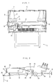
- FIG. 1 shows a flat knitting machine 1 equipped with tension switch assemblies.
- Cones 3 each having wound thereon a yarn 2 for knitting are placed respectively on cone stands 5 mounted on a cone stand plate 4.
- the yarn 2 paid off from the cone 3 on each cone stand 5 is guided by unillustrated yarn guides arranged at different locations on the path of feed of the yarn to the tension switch assembly 7 mounted on a support member 6 which is provided above the stand plate 4 transversely of the machine.
- the yarn 2 passing through the assembly 7 is given a suitable tension by a side tension 9 disposed at each side of a needle bed 8, fed by a yarn feeder 13 to the hook of an unillustrated needle and knitted into a fabric.
- a carriage 10 is slidable on the needle bed 8 in opposite directions transversely of the machine 1 and has a coupling, on which a carrier control 11 is provided for moving a yarn carrier 12 therewith.
- the yarn feeder 13 is attached to the carrier 12, and the needle is slidable forward and backward by an unillustrated cam which is mounted on the carriage 10.
- the assembly 7 has a main body 15 which is attached to the support member 6 provided above the cone stand plate 4 of the machine 1.
- An arm 16 is made of a resilient member and has one end bent into a spring and pivoted to the main body 15 and a forward end which is biased by the resiliency of the arm so as to impart a tension to the yarns in travel.
- a yarn conductor 20 is rotatably attached to a portion of the arm 16 in the vicinity of its forward end, i.e., to the forward end in the present embodiment, by a rotational pin 19 serving as a supporting point for rotation relative to the arm 16.
- At least a specified amount of pivotal movement of the arm 16 is detected by a detection arm 17, and the pivotal movement of the arm 17 is detected by a sensor 18, which in turn feeds a stop signal to an unillustrated control unit of the knitting machine.
- the yarns 2, 2 paid off from the different cones 3, 3, passed through the respective guides and inserted through the common yarn guide 14 of the assembly 7 are inserted as arranged side by side through a known yarn brake 21, knot detector 22, yarn guide 23, yarn guide 24 and yarn guide 25 in the order mentioned.
- the sensor 18 serves also as a sensor for the knot detector 22 and stops the machine 1 upon detecting a knot.
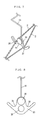
- FIG. 4 shows the yarn conductor 20 rotatably supported by the forward end of the arm 16.
- the yarn conductor 20 supported by the forward end of the arm 16 is provided with a pin, e.g., rotational pin 19, and a pair of opposite yarn supports 26, 27 on opposite sides of the pin 19 at the lower side thereof for retaining the respective yarns 2, 2 thereon.
- a pin e.g., rotational pin 19
- a pair of opposite yarn supports 26, 27 on opposite sides of the pin 19 at the lower side thereof for retaining the respective yarns 2, 2 thereon.
- FIG. 5 is a view in section taken along the line X-X in FIG. 4, and FIG. 6 is a perspective view showing how the yarn conductor 2 is attached to the arm 16.
- the conductor 20 is attached to the forward end of the arm 16 rotatably relative to the arm 16 by the rotational pin 19 serving as a supporting point for rotation relative to the arm 16 and by a stopper 28 such as a nut or crimped ring.
- FIG. 7 shows the yarns 2, 2 retained on the pair of yarn supports 26, 27, respectively.
- the supports 26, 27 each comprise, for example, a hook.
- the opposite supports 26, 27 retain the two yarns 2, 2, respectively. Accordingly, the yarns 2, 2 are tensioned by a force from the arm 16, which is in turn held shifted downward by the yarns 2, 2.
- the yarns 2, 2 are positioned side by side by the yarn guides 24 and 25 to the front and rear of the conductor 20.
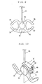
- FIG. 8 shows a second embodiment.
- a yarn conductor 29 is formed with a pair of opposite yarn supports 31, 32 on opposite sides of a rotational pin 30, respectively.
- a yarn support portion 33 in the form of a hole is formed under the rotational pin 30.
- the support portion 33 is not limited to a hole insofar as the yarn can be inserted therethrough.
- FIG. 9 shows a third embodiment.
- a yarn conductor 34 is formed with a pair of opposite yarn supports 36, 37 on opposite sides of a rotational pin 35, respectively, and has yarn stoppers 38, 39 opposed to the respective supports 36, 37 for preventing the yarn from jumping out.
- a yarn support portion 40 is formed also in this embodiment for use in detecting a break in only one yarn.
- the base end of the arm 16 is bent into a spring and attached to the main body 15, and the forward end of the arm 16 is biased upward by the resiliency of the arm 16 itself, whereas a separate spring may be attached to the arm 16 for upwardly biasing the forward end of the arm 16 by the spring.
- the detection arm 17 and mechanical sensor 18 for detecting the pivotal movement of the arm 16 also usable is a sensor other than the mechanical sensor, such as an optical sensor or electrical sensor.
- the yarn conductor 20 is supported directly by the forward end of the arm 16.
- a yarn conductor 41 and an intermediate member 42 may be rotatably supported by a pin, i.e., rotational pin 43, and a stopper 44.
- An arm 16 has at its forward end a U-shaped engaging portion 45 which is engaged in a U-shaped groove 46 formed in the intermediate member 42.
- Conventional tension switch assemblies have an arm 16 which is bent at its forward end into a U-shaped loop for inserting a yarn 2 therethrough, so that when the bent portion is engaged as the engaging portion 45 in the intermediate member 42, the conventional assembly can be used as it is.
- the conductor 41 is rotatable relative to the intermediate member 42, and the arm 16 is engaged in the U-shaped groove 46 of the intermediate member 42.
- the method of attaching the yarn conductor to the arm is not limited to that shown in the embodiment.
- the pair of opposite yarn supports 26, 27 are caused to retain yarns 2, 2 thereon, whereby the arm 16 is held downwardly shifted, with the force of the yarns 2, 2 acting against an upwardly biasing force.
- the yarns 2, 2 are slightly raised upward by being pulled by the arm 16 and a suitable tension is given.
- the forces exerted by the yarns 2, 2 respectively on the pair of yarn supports 26, 27 are in balance, and the torques delivered from the yarns 2, 2 to the rotational pin 19 offset each other. Consequently, the yarn conductor 20 remains unrotated in balance.
- FIG. 13 shows the assembly with the yarn 2 released from the conductor 20.
- the yarn 2 extends straight between the yarn guides 24, 25, and the arm 16 is in an upwardly moved position.
- the yarn conductor 34 has the yarn stoppers 38, 39 for preventing yarns 2 from jumping out.
- the stopper 38 or 39 precludes the yarn 2 from slipping off the yarn conductor 34.
- marked variations in the tension acting on the yarns 2, 2 are detectable utilizing the fact that the yarns 2, 2 readily slip off from the supports (26, 27), (31, 32). More specifically, if a great difference occurs between the tensions on the pair of yarns 2, 2 retained on the yarn supports (26, 27) or (31, 32), one of the yarns 2, 2 rises off the support and is released therefrom to rotate the yarn conductor 20 or 29. This serves not only to detect a yarn break but also to prevent faults from occurring in the knitted fabric which are likely to result from a knitting operation involving a great difference between the tensions on the respective yarns 2, 2.
- FIGS. 14 to 16 show a fourth embodiment.
- this embodiment has a rotatable lever 50 attached to the base end of a lever 16, and a spring coil 51 for biasing the lever 50 to bias the arm 16 upward.
- the biasing degree is adjustable by rotating an adjusting switch 52 attached to the other end of the coil 51.
- Indicated at 53 is a limit switch. When the arm 16 rotates upward, a notched portion of the lever 50 pushes an actuator of the limit switch 53, whereby a yarn break is detected.
- Indicated at 22A, 22B are a pair of knot detectors which per se are known.
- the knot detector 22A or 22B When the width of the yarn 2 becomes larger than the clearance between the main body 15 and the knot detector 22A or 22B, the knot detector 22A or 22B is pushed leftward in the drawing to actuate a limit switch 54 or 55 to detect a knot.
- the clearance between the main body 15 and the knot detector 22A or 22B is adjustable by an unillustrated pin.
- the detector 22A detects a thick knot and stops the knitting machine 1.
- the detector 22B detects a thin knot, whereupon the detector temporarily reduces the knitting speed of the machine 1.
- Indicated at 56 is a signal transmission code, at 57 an intermediate member attached to the forward end of the arm 16, at 58 a yarn conductor, at 59 a yarn guide for feeding the yarn 2 to a side tension 9, and at 60 a flat member attached to the yarn guide 59.
- the intermediate member 57 is so constructed that a U-shaped tongue is sandwiched between two plates.
- the two plates are separate except where the tonque is positioned to provide a clearance, in which an upper portion of the yarn conductor 58 is accommodated as shown in FIG. 15.
- the intermediate member 57 is prepared, for example, from a plastics by molding the tongue and the two plates into an integral piece.
- the arm 16 has at its forward end a U-shaped engaging portion 45, which is engaged in a U-shaped groove 46 around the U-shaped tongue.
- the yarn conductor 58 is rotatably held to the intermediate member 57.
- a pin 61 formed on one of the plates of the intermediate member 57 extends through a pinhole 62 formed in a middle upper portion of the yarn conductor 58 and serving as a rotation supporting point.
- the conductor 58 is held between the two plates and rotatable about the pin 61.
- Indicated at 63, 64 are a pair of yarn supports arranged on opposite sides of the pinhole 62 at the lower side of the pinhole 62.
- Indicated at 65 is a yarn support portion, and at 66 a flat face formed at the lower end of the conductor 58.
- the yarn conductor 58 of the present embodiment is also usable for retaining a pair of yarns 2, 2 on the respective yarn supports 63, 64, or for supporting a yarn on the support portion 65 only.
- the flat member 60 for example, of of plastics is attached to the yarn guide 59, which is provided with three yarn support portions 67, 68, 69.
- the flat member 60 and the flat face 66 are provided for the reason to be described below.
- the conductor 58 is liable to descend into contact with the yarn guide 59. If the conductor 58 comes into contact with the guide 59 in the absence of the flat member 60 and the flat face 66, the conductor 58 is liable to rotate to release the yarn 2.
- the flat member 60 and the flat face 66 are therefore provided to prevent the yarn conductor 58 from rotation upon coming into contact with the yarn guide 59 and facilitate setting of the yarn 2.
- the three yarn support portions 67, 68, 69 are provided to thereby separate the yarns 2, 2 sent forward as closely arranged side by side to the yarn guide 24 and render the yarns easy to set on the respective supports 63, 64 because the yarns 2, 2, if so arranged at both the yarn guides 59, 24, are difficult to set as separated on the supports 63, 64.
- the embodiment has the three yarn support portions 67, 68, 69, two of them may be provided in actuality.
- the yarn support portions 67, 68, 69 may alternatively be provided for the yarn guide 24 instead of the yarn guide 59 for the guide 24 to separate the closely arranged yarns 2, 2.
- the embodiment is the same as the embodiment of FIGS. 10 and 11 with the exception of the different mechanism for detecting the pivotal movement of the arm 16, use of the new intermediate member 57 and yarn conductor 58, the combination of flat face 66 and flat member 60 for preventing inadvertent rotation of the yarn conductor 58, and use of the three yarn support portions 67, 68, 69 to render yarns easily settable on the yarn supports 63, 64.
- a pair of arms 16 may be provided respectively on opposite sides of the main body 15. In this case a break in up to four yarns 2 can be detected by one tension switch assembly. Even when the pair of arms 16 are used, the yarn brake 1, knot detectors 22A, 22B and yarn guide 24 may each be provided singly, and these means are serviceable for up to four yarns 2.
Landscapes
- Engineering & Computer Science (AREA)
- Textile Engineering (AREA)
- Knitting Machines (AREA)
- Filamentary Materials, Packages, And Safety Devices Therefor (AREA)
Claims (10)
- Spannungswächterbaugruppe (7) zur Verwendung bei Strickmaschinen (1), welche einen Arm (16), einen Hauptkörper (15) und einen Sensor (18) zum Erfassen einer Schwenkbewegung des Arms umfaßt, wobei der Arm ein vorderes Ende zum Führen eines Fadens (2, 2) in der Nähe von diesem aufweist sowie ein schwenkbar an dem Hauptkörper angebrachtes Basisende, um den Faden zu spannen, wobei der Sensor betätigbar ist, um die Schwenkbewegung des Arms aufgrund eines Bruchs in dem geführten Faden zu erfassen, um den Betrieb der Strickmaschine anzuhalten, wobei die Spannungswächterbaugruppe dadurch gekennzeichnet ist, daß ein Fadenleitorgan (20; 29; 34; 41; 58) einen Drehstützpunkt (19; 30; 35; 43; 62) aufweist und wobei ein Paar von Fadenhaltern (26, 27; 31, 32; 36, 37; 63, 64), die jeweils auf entgegengesetzten Seiten des Stützpunktes angeordnet sind, direkt oder indirekt an einem Abschnitt des Arms (16) in der Nähe seines vorderen Endes um den Stützpunkt schwenkbar angebracht ist.
- Spannungswächterbaugruppe zur Verwendung bei Strickmaschinen nach Anspruch 1, welche dadurch gekennzeichnet ist, daß bei einem Bruch, der in einem eines Paars von Fäden (2, 2), die jeweils an dem Paar von Fadenhaltern (26, 27; 31, 32; 36, 37; 63, 64) gehalten sind, auftritt, von den Fäden an dem Drehstützpunkt ausgeübte Drehmomente aus dem Gleichgewicht gebracht werden, um das Fadenleitorgan (20; 29; 34; 41; 58) zu drehen und folglich den anderen Faden aus dem Fadenhalter freizugeben.
- Spannungswächterbaugruppe zur Verwendung bei Strickmaschinen nach Anspruch 1 oder 2, welche dadurch gekennzeichnet ist, daß der Drehstützpunkt (19; 30; 35; 43; 62) ein Stift oder ein Stiftloch ist.
- Spannungswächterbaugruppe zur Verwendung bei Strickmaschinen nach Anspruch 1, 2 oder 3, welche dadurch gekennzeichnet ist, daß ein Zwischenelement (42; 57) mit dem vorderen Ende des Arms (16) in Eingriff ist und das Fadenleitorgan (41; 58) an dem Zwischenelement (42; 57) um den Drehstützpunkt (43; 62) schwenkbar angebracht ist.
- Spannungswächterbaugruppe zur Verwendung bei Strickmaschinen nach Anspruch 4, welche dadurch gekennzeichnet ist, daß der Arm (16) einen U-förmigen Eingriffsabschnitt (45) an seinem vorderen Ende aufweist, wobei das Zwischenelement (42; 57) eine U-förmige Ausnehmung (46) aufweist und wobei der U-förmige Eingriffsabschnitt (45) in die U-förmigen Ausnehmung (46) eingreift.
- Spannungswächterbaugruppe zur Verwendung bei Strickmaschinen nach einem der vorhergehenden Ansprüche, welche dadurch gekennzeichnet ist, daß der Hauptkörper mit einer Fadenbremse (21) versehen ist und wenigstens ein Fadenknotendetektor (22) und das Paar von Fäden (2, 2), die an dem Paar von Fadenhaltern (26, 27; 31, 32; 36, 37; 63, 64) gehalten sind, gemeinsam der Fadenbremse (21) und dem Knotendetektor (22) zugeordnet sind.
- Spannungswächterbaugruppe zur Verwendung bei Strickmaschinen nach einem der vorhergehenden Ansprüche, welche dadurch gekennzeichnet ist, daß das Fadenleitorgan (29; 34, 58) mit einem Fadenhalterabschnitt (33; 40; 65) auf einer Seite des Drehstützpunkts (30; 35; 62) gegenüber dem Arm (16) und zwischen den Fadenhaltern (31, 32; 36, 37; 63, 64) versehen ist.
- Spannungswächterbaugruppe zur Verwendung bei Strickmaschinen nach einem der vorhergehenden Ansprüche, welche dadurch gekennzeichnet ist, daß das Fadenleitorgan (34) mit Fadenstoppern (38, 39) gegenüber den jeweiligen Fadenhaltern (36, 37) versehen ist, um zu verhindern, daß der Faden herausspringt.
- Spannungswächterbaugruppe zur Verwendung bei Strickmaschinen nach einem der vorhergehenden Ansprüche, welche dadurch gekennzeichnet ist, daß der Hauptkörper (15) an seinem einen Ende mit einem Fadenführer (59) versehen ist, wobei das Fadenleitorgan (58) an seinem dem Arm (16) entgegengesetzten Ende eine ebene Fläche (66) aufweist und wobei ein Flachelement (60) gegenüber der ebenen Fläche (66) des Fadenführers (59) positioniert ist.
- An ein vorderes Ende eines Erfassungsarms (16) für eine Fadenbremse einer Spannungswächterbaugruppe (7) einer Strickmaschine anzubringendes Fadenleitorgan zum Führen eines Fadens (2), wobei das Fadenleitorgan dadurch gekennzeichnet ist, daß das Leitorgan (20; 29; 34; 41; 58) etwa in seiner Mitte einen Drehstützpunkt (19; 30; 35; 43; 62) aufweist sowie ein Paar von Fadenhaltern (26, 27; 31, 32; 36, 37; 63, 64), die jeweils auf entgegengesetzten Seiten des Stützpunktes angeordnet sind.
Applications Claiming Priority (2)
| Application Number | Priority Date | Filing Date | Title |
|---|---|---|---|
| JP6000673A JP2794158B2 (ja) | 1994-01-10 | 1994-01-10 | 編機用糸切れ検出装置 |
| JP673/94 | 1994-01-10 |
Publications (2)
| Publication Number | Publication Date |
|---|---|
| EP0666347A1 EP0666347A1 (de) | 1995-08-09 |
| EP0666347B1 true EP0666347B1 (de) | 1997-03-19 |
Family
ID=11480269
Family Applications (1)
| Application Number | Title | Priority Date | Filing Date |
|---|---|---|---|
| EP95300115A Expired - Lifetime EP0666347B1 (de) | 1994-01-10 | 1995-01-10 | Spannungswächter und Garnführer für Strickmaschine |
Country Status (4)
| Country | Link |
|---|---|
| US (1) | US5544503A (de) |
| EP (1) | EP0666347B1 (de) |
| JP (1) | JP2794158B2 (de) |
| DE (1) | DE69500183T2 (de) |
Families Citing this family (9)
| Publication number | Priority date | Publication date | Assignee | Title |
|---|---|---|---|---|
| US6126102A (en) * | 1998-11-10 | 2000-10-03 | E. I. Du Pont De Nemours And Company | Apparatus for high speed beaming of elastomeric yarns |
| DE10008353A1 (de) * | 2000-02-23 | 2001-09-06 | Zimmer Ag | Verfahren und Vorrichtung zum Feststellen von Verdickungen in einem laufenden Faden |
| CN102191625B (zh) * | 2011-04-13 | 2012-11-21 | 江苏金龙科技股份有限公司 | 电脑针织横编机的纱线预张力调整装置的断纱报警机构 |
| CN102191623B (zh) * | 2011-04-13 | 2012-11-07 | 江苏金龙科技股份有限公司 | 电脑针织横编机的纱线预张力调整机构的断纱报警装置 |
| CN102888706B (zh) * | 2012-10-22 | 2013-11-20 | 江苏金龙科技股份有限公司 | 电脑针织横编机的导纱装置 |
| CN102888707B (zh) * | 2012-10-22 | 2014-04-16 | 江苏金龙科技股份有限公司 | 具有纱线结节报警功能的电脑针织横编机的导纱装置 |
| CN103469471B (zh) * | 2013-09-10 | 2014-12-24 | 江苏金龙科技股份有限公司 | 纱线张力调整装置的断纱信号触发机构 |
| US10647539B2 (en) * | 2015-02-09 | 2020-05-12 | Nv Bekaert Sa | Tension buffer system for multi-wire pay-off system |
| CN114016204B (zh) * | 2021-11-22 | 2022-07-22 | 江南大学 | 一种横编结头全自动处理连续编织工艺方法 |
Family Cites Families (7)
| Publication number | Priority date | Publication date | Assignee | Title |
|---|---|---|---|---|
| FR1042889A (fr) * | 1950-04-24 | 1953-11-04 | Dispositif casse-fil | |
| JPS4210108Y1 (de) * | 1965-10-30 | 1967-06-02 | ||
| DE2919916C2 (de) * | 1979-05-17 | 1987-01-15 | H. Stoll Gmbh & Co, 7410 Reutlingen | Fadenzuführeinrichtung für Flachstrickmaschinen |
| DE3310132C1 (de) * | 1983-03-21 | 1984-05-10 | H. Stoll Gmbh & Co, 7410 Reutlingen | Fadenbremse für Flachstrickmaschinen |
| US4551591A (en) * | 1984-06-18 | 1985-11-05 | Jones Robert E | Stop motion switch |
| JPS6314594U (de) * | 1986-07-15 | 1988-01-30 | ||
| DE3633108A1 (de) * | 1986-09-30 | 1988-03-31 | Stoll & Co H | Fadenwaechter fuer textilmaschinen |
-
1994
- 1994-01-10 JP JP6000673A patent/JP2794158B2/ja not_active Expired - Fee Related
-
1995
- 1995-01-06 US US08/369,693 patent/US5544503A/en not_active Expired - Fee Related
- 1995-01-10 EP EP95300115A patent/EP0666347B1/de not_active Expired - Lifetime
- 1995-01-10 DE DE69500183T patent/DE69500183T2/de not_active Expired - Fee Related
Also Published As
| Publication number | Publication date |
|---|---|
| JP2794158B2 (ja) | 1998-09-03 |
| DE69500183T2 (de) | 1997-06-26 |
| JPH07207554A (ja) | 1995-08-08 |
| EP0666347A1 (de) | 1995-08-09 |
| US5544503A (en) | 1996-08-13 |
| DE69500183D1 (de) | 1997-04-24 |
Similar Documents
| Publication | Publication Date | Title |
|---|---|---|
| US5544503A (en) | Tension switch assembly and yarn conductor of knitting machine | |
| JP2541574B2 (ja) | 電子的糸張力制御機能を有する給糸装置 | |
| JPH0155181B2 (de) | ||
| US4271687A (en) | Rapid maintenance thread or yarn supply apparatus, particularly for circular knitting machines | |
| US3950966A (en) | Demand responsive positive feed device for knitting machine | |
| JPH0210150Y2 (de) | ||
| US4545543A (en) | Yarn feed device | |
| EP0333482A1 (de) | Positive Fadenzuführungsvorrichtung für eine Rundstrickmaschine | |
| US5211709A (en) | Stop motion device for strand processing machine | |
| JP2007107134A (ja) | 横編機の糸案内装置 | |
| US4353227A (en) | Tension indicator for elastomeric yarn | |
| KR100449937B1 (ko) | 필러 정지부를 구비한 얀 공급기 | |
| US4271686A (en) | Thread or yarn supply apparatus with movable thread supply guide means, particularly for circular knitting machines | |
| EP0602460B1 (de) | System zum Erfassen eines Litzenbruchs | |
| GB2120284A (en) | Yarn feeding apparatus for multi-feed knitting machines | |
| US3365991A (en) | Strand detector, clamp and severing device | |
| JPS63501964A (ja) | 紡績糸供給装置 | |
| US4165048A (en) | Positive feed | |
| EP0905078B1 (de) | Spulautomat | |
| US3967471A (en) | Automatic knitting yarn replacing apparatus | |
| US5806744A (en) | Apparatus for feeding and tensioning threads in a textile machine | |
| SU1065510A1 (ru) | Устройство дл прекращени подачи нити на текстильных машинах с трехвалковым питающим прибором,преимущественно на пр дильных и крутильных машинах | |
| GB2027456A (en) | Thread supply apparatus for circular knitting machines | |
| GB2138846A (en) | Yarn feed device | |
| JPH0223620B2 (de) |
Legal Events
| Date | Code | Title | Description |
|---|---|---|---|
| PUAI | Public reference made under article 153(3) epc to a published international application that has entered the european phase |
Free format text: ORIGINAL CODE: 0009012 |
|
| AK | Designated contracting states |
Kind code of ref document: A1 Designated state(s): DE ES FR GB IT |
|
| 17P | Request for examination filed |
Effective date: 19950710 |
|
| GRAG | Despatch of communication of intention to grant |
Free format text: ORIGINAL CODE: EPIDOS AGRA |
|
| 17Q | First examination report despatched |
Effective date: 19960624 |
|
| GRAH | Despatch of communication of intention to grant a patent |
Free format text: ORIGINAL CODE: EPIDOS IGRA |
|
| GRAH | Despatch of communication of intention to grant a patent |
Free format text: ORIGINAL CODE: EPIDOS IGRA |
|
| GRAA | (expected) grant |
Free format text: ORIGINAL CODE: 0009210 |
|
| ITF | It: translation for a ep patent filed | ||
| AK | Designated contracting states |
Kind code of ref document: B1 Designated state(s): DE ES FR GB IT |
|
| PG25 | Lapsed in a contracting state [announced via postgrant information from national office to epo] |
Ref country code: ES Free format text: THE PATENT HAS BEEN ANNULLED BY A DECISION OF A NATIONAL AUTHORITY Effective date: 19970319 |
|
| REF | Corresponds to: |
Ref document number: 69500183 Country of ref document: DE Date of ref document: 19970424 |
|
| ET | Fr: translation filed | ||
| PLBE | No opposition filed within time limit |
Free format text: ORIGINAL CODE: 0009261 |
|
| STAA | Information on the status of an ep patent application or granted ep patent |
Free format text: STATUS: NO OPPOSITION FILED WITHIN TIME LIMIT |
|
| 26N | No opposition filed | ||
| REG | Reference to a national code |
Ref country code: GB Ref legal event code: IF02 |
|
| PGFP | Annual fee paid to national office [announced via postgrant information from national office to epo] |
Ref country code: IT Payment date: 20060131 Year of fee payment: 12 |
|
| PGFP | Annual fee paid to national office [announced via postgrant information from national office to epo] |
Ref country code: DE Payment date: 20070104 Year of fee payment: 13 |
|
| PGFP | Annual fee paid to national office [announced via postgrant information from national office to epo] |
Ref country code: GB Payment date: 20070110 Year of fee payment: 13 |
|
| PGFP | Annual fee paid to national office [announced via postgrant information from national office to epo] |
Ref country code: FR Payment date: 20070109 Year of fee payment: 13 |
|
| GBPC | Gb: european patent ceased through non-payment of renewal fee |
Effective date: 20080110 |
|
| PG25 | Lapsed in a contracting state [announced via postgrant information from national office to epo] |
Ref country code: DE Free format text: LAPSE BECAUSE OF NON-PAYMENT OF DUE FEES Effective date: 20080801 |
|
| REG | Reference to a national code |
Ref country code: FR Ref legal event code: ST Effective date: 20081029 |
|
| PG25 | Lapsed in a contracting state [announced via postgrant information from national office to epo] |
Ref country code: GB Free format text: LAPSE BECAUSE OF NON-PAYMENT OF DUE FEES Effective date: 20080110 |
|
| PG25 | Lapsed in a contracting state [announced via postgrant information from national office to epo] |
Ref country code: FR Free format text: LAPSE BECAUSE OF NON-PAYMENT OF DUE FEES Effective date: 20080131 |
|
| PG25 | Lapsed in a contracting state [announced via postgrant information from national office to epo] |
Ref country code: IT Free format text: LAPSE BECAUSE OF NON-PAYMENT OF DUE FEES Effective date: 20070110 |