EP0664261B1 - Endless conveyor - Google Patents
Endless conveyor Download PDFInfo
- Publication number
- EP0664261B1 EP0664261B1 EP94116333A EP94116333A EP0664261B1 EP 0664261 B1 EP0664261 B1 EP 0664261B1 EP 94116333 A EP94116333 A EP 94116333A EP 94116333 A EP94116333 A EP 94116333A EP 0664261 B1 EP0664261 B1 EP 0664261B1
- Authority
- EP
- European Patent Office
- Prior art keywords
- conveyor
- dampener
- surging
- inertia
- chain
- Prior art date
- Legal status (The legal status is an assumption and is not a legal conclusion. Google has not performed a legal analysis and makes no representation as to the accuracy of the status listed.)
- Expired - Lifetime
Links
- 230000002411 adverse Effects 0.000 claims description 15
- 230000001629 suppression Effects 0.000 claims description 15
- 238000000034 method Methods 0.000 claims description 14
- 238000004891 communication Methods 0.000 claims description 6
- 230000008878 coupling Effects 0.000 claims description 4
- 238000010168 coupling process Methods 0.000 claims description 4
- 238000005859 coupling reaction Methods 0.000 claims description 4
- 239000007787 solid Substances 0.000 description 16
- 238000010276 construction Methods 0.000 description 9
- 238000006073 displacement reaction Methods 0.000 description 8
- 230000005484 gravity Effects 0.000 description 7
- 230000001419 dependent effect Effects 0.000 description 6
- 238000004519 manufacturing process Methods 0.000 description 6
- 230000032258 transport Effects 0.000 description 6
- 238000004364 calculation method Methods 0.000 description 5
- 239000000463 material Substances 0.000 description 5
- 230000002829 reductive effect Effects 0.000 description 5
- 238000006467 substitution reaction Methods 0.000 description 5
- 230000008859 change Effects 0.000 description 4
- 230000000694 effects Effects 0.000 description 4
- 229910000831 Steel Inorganic materials 0.000 description 3
- 238000013016 damping Methods 0.000 description 3
- 230000003247 decreasing effect Effects 0.000 description 3
- 238000009434 installation Methods 0.000 description 3
- 230000000717 retained effect Effects 0.000 description 3
- 239000010959 steel Substances 0.000 description 3
- 230000007423 decrease Effects 0.000 description 2
- 238000001125 extrusion Methods 0.000 description 2
- 210000000664 rectum Anatomy 0.000 description 2
- 125000006850 spacer group Chemical group 0.000 description 2
- 238000005303 weighing Methods 0.000 description 2
- 229910000639 Spring steel Inorganic materials 0.000 description 1
- 230000015572 biosynthetic process Effects 0.000 description 1
- 150000001875 compounds Chemical class 0.000 description 1
- 238000004590 computer program Methods 0.000 description 1
- 238000010586 diagram Methods 0.000 description 1
- 230000005284 excitation Effects 0.000 description 1
- 239000007788 liquid Substances 0.000 description 1
- 230000005923 long-lasting effect Effects 0.000 description 1
- 238000005461 lubrication Methods 0.000 description 1
- 239000011159 matrix material Substances 0.000 description 1
- 230000007246 mechanism Effects 0.000 description 1
- 230000010355 oscillation Effects 0.000 description 1
- 230000002028 premature Effects 0.000 description 1
- 230000009467 reduction Effects 0.000 description 1
- 230000004044 response Effects 0.000 description 1
- 230000003068 static effect Effects 0.000 description 1
- 238000003860 storage Methods 0.000 description 1
Images

Classifications
-
- B—PERFORMING OPERATIONS; TRANSPORTING
- B65—CONVEYING; PACKING; STORING; HANDLING THIN OR FILAMENTARY MATERIAL
- B65G—TRANSPORT OR STORAGE DEVICES, e.g. CONVEYORS FOR LOADING OR TIPPING, SHOP CONVEYOR SYSTEMS OR PNEUMATIC TUBE CONVEYORS
- B65G17/00—Conveyors having an endless traction element, e.g. a chain, transmitting movement to a continuous or substantially-continuous load-carrying surface or to a series of individual load-carriers; Endless-chain conveyors in which the chains form the load-carrying surface
- B65G17/002—Conveyors having an endless traction element, e.g. a chain, transmitting movement to a continuous or substantially-continuous load-carrying surface or to a series of individual load-carriers; Endless-chain conveyors in which the chains form the load-carrying surface comprising load carriers resting on the traction element
-
- B—PERFORMING OPERATIONS; TRANSPORTING
- B65—CONVEYING; PACKING; STORING; HANDLING THIN OR FILAMENTARY MATERIAL
- B65G—TRANSPORT OR STORAGE DEVICES, e.g. CONVEYORS FOR LOADING OR TIPPING, SHOP CONVEYOR SYSTEMS OR PNEUMATIC TUBE CONVEYORS
- B65G2201/00—Indexing codes relating to handling devices, e.g. conveyors, characterised by the type of product or load being conveyed or handled
- B65G2201/02—Articles
Definitions
- This invention relates to an endless conveyor for transporting articles of manufacture and more particularly to a method and conveyor which reduces the amplitude of surging during operation.
- conveyors are commonly used to transport workpieces from workstation to workstation where manufacturing operations are performed on each workpiece.
- these conveyors consist of a pair of laterally spaced apart chains in closed loops that are carried by sprockets on a shaft at each end of the loop.
- Each chain is slidably guided and supported by a support rail attached to the conveyor frame.
- the chains are operably connected to several pallets, usually enough to fill the conveyor, carrying workpieces to transport the workpieces from station to station.
- the conveyor also serves as a storage system for the pallets and workpieces.
- Stick-slip an operating condition known as "stick-slip” where at least one portion of a conveyor chain alternately decelerates and accelerates due to friction between the chain and guide rail and because the chain behaves like a massive spring alternately storing and releasing energy as the chain sticks and slips.
- Stick-slip in conveyors has been more specifically referred to as “harmonic oscillation stick-slip” because during surging it has been found that a conveyor chain will surge at a specific frequency which varies only slightly with changing lubrication conditions and the location of the load on a given conveyor.
- a still further proposed solution has been to add a brake to the tail end of the conveyor opposite the drive shaft to continuously dissipate energy for preventing surging.
- brakes have been found to prevent the onset of surging under an extremely narrow range of conveyor operating conditions, they also do not consistently prevent surging under the wide variety of conditions generally encountered during actual conveyor operation.
- Such a conveyor is known from the Soviet Patent Abstract 90-005549/01 which shows several sprocket wheels supporting endless chains which support a load carrying platform.
- the sprockets are mounted on a shaft which has a paddle on one end.
- the paddle is mounted in a box being filled with viscous liquid.
- This viscous retarder provides increased resistance to rotation on the shaft, thereby dampening ordinary vibration and discipating energy in the form of heat. This increases the power input required to operate the conveyor.
- a conveyor according to the invention is defined by claim 1.
- Methods according to the invention for reducing surging vibration are defined in independent claims 7 and 13.
- the conveyor has an endless, flexible roller chain in a closed loop received on laterally spaced apart drive and idle sprockets at opposite ends of the loop. If the conveyor has two or more loops of chain, each idle sprocket is independently journalled to prevent torsion-induced windup, which can occur with a common take-up shaft during operation, from exciting the shaft and causing a vibration to be transmitted to one or more of the chains.
- a separate surge dampener is attached to each idle sprocket of each chain to dramatically reduce or even virtually eliminate the amplitude of surging.
- the dampener comprises a flywheel disc coupled to the idle sprocket by a spring and has a natural frequency that is tuned to the frequency at which the conveyor is surging.
- the surge dampener can be mounted on conveyors not experiencing surging as a precaution to prevent the occurrence of surging, especially where the natural frequency of the conveyor falls within the natural frequency range making it susceptible to surging, but is particularly well suited for retrofit use with conveyors that are experiencing surging during actual operation.
- the surge frequency of the conveyor without any dampener installed is preferably measured and the mass moment of inertia of the conveyor without any dampener installed is determined.
- the mass moment of inertia of the dampener flywheel is multiplied by a predetermined inertia ratio that will provide the dampener with a sufficiently wide bandwidth of surge suppression for preventing surging from affecting the operation of the conveyor should the dampener not be precisely tuned to the surge frequency or should the conveyor natural frequency shift during operation.
- the mass and physical dimensions of the flywheel are determined for constructing the flywheel.
- the spring rate of the dampener spring is chosen to impart to the dampener a natural frequency about equal to the surge frequency.
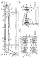
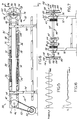
- FIG. 1 illustrates an over-under type conveyor apparatus 30 having a frame 32 supporting an endless accumulating conveyor 34 for transporting pallets 36 carrying workpieces thereon along an assembly line (not shown).
- the conveyor 34 comprises a pair of endless, flexible roller chains 38 & 40 in closed loops that are laterally spaced apart by and carried on drive sprockets 42 which are preferably keyed to a drive shaft 46 at one end of the frame 32 and take-up or idle sprockets 44 which are preferably keyed to a tail or take-up shaft 48 at the opposite end of the frame 32.
- the conveyor chains 38, 40 are driven by a preferably electric motor drive 50 that is operably connected to a sprocket (not shown) keyed to the drive shaft 46 by an endless flexible member 52 such as a chain or belt.
- the drive shaft 46 is a transverse horizontal shaft that is journalled for rotation in a pair of pillow blocks mounted to plates 54 secured to one end of the frame 32, only one of which is shown in FIG. 1.
- the take-up shaft 48 is also journalled for rotation in pillow blocks mounted to plates 58 & 60 secured to the frame 32 at the opposite end. As is shown more clearly in FIG.
- the take-up shaft 48 is preferably split into two shaft sections 62 & 64 that are journalled adjacent their innermost ends by a pair of bearings 66 & 68 carried by a mounting block 70 to permit each conveyor chain to move on its idle sprocket 44 independently of the other chain for preventing torsion-induced windup of the take-up shaft 48 and/or drive shaft 46 during conveyor operation from exciting the shaft at its torsional frequency and causing a vibration to he transmitted to one or both chains 38, 40.
- each chain 38, 40 is an endless 3-strand or 4-strand (the 4th strand is shown in phantom in FIGS. 2, 4 & 5) roller chain.
- Each chain 38, 40 extends over the drive and idle sprockets 42 & 44, respectively, with the sprocket teeth engaging between the rollers of the two outermost strands of each 3-strand chain or the two middle strands of each 4-strand chain.
- each chain 38, 40 has an upper run 72 and a lower run 74 connected by curved sections 76 & 78 extending around the sprockets 42, 44 on shafts 46, 48.
- the conveyor has a chain tensioning device 56 adjacent each idle sprocket 44 and in communication with chains 38 & 40 for enabling adjustment of the tension of each chain.
- each chain tensioning device 56 is isolated from the chain it is associated with to prevent adding an additional degree of freedom to the conveyor and increasing the amplitude of surging vibration.
- the upper runs 72 of the two chains 38, 40 are horizontal and parallel to one another, and are guided and supported by horizontal guide rails 80, 82, 84 & 86 connected to upper rail extrusions 88 & 90 which are in turn attached to legs 92 & 94 extending vertically upwardly from the floor.
- rails 84 & 86 bear against the underside of the middle strand of the 3-strand chains 38, 40, while rails 80 & 82 abut against the top of the outermost chain strands for slidably guiding the chains 38, 40 along the conveyor 34 and cantilevering the chains 38, 40 therefrom for enabling the pallets 36 to be supported on the innermost chain strands during operation.
- the lower chain runs 74 are also horizontal and parallel to one another, and are guided and supported by horizontal guide rails 96, 98, 100 & 102 connected to lower rail extrusions 104, 106 which are attached to the conveyor frame 32 by legs 92 & 94.
- Rails 100 & 102 bear against the underside of the middle strand of the 3-strand chains while rails 96 & 98 abut against the outermost strand for slidably guiding the chains along the rails and cantilevering the chains therefrom for enabling the pallets 36 to be supported on the innermost chain strands during operation of the conveyor 34.
- the conveyor apparatus 30 is designed to slidably support and locate the pallets 36 and transport them over both the upper and lower runs 72, 74.
- the pallets 36 have a pair of spaced apart shoes 108 & 110 attached to the underside thereof. Each shoe has a pair of vertically spaced apart guide bars 112 & 114 which are parallel to one another and extend lengthwise of the pallet 36.
- the upper guide bars 112 of each pallet shoe 108, 110 ride on the innermost strands of the chains.
- the pallet 36 is inverted and the lower guide bars 114 ride on the rollers of the innermost strands of the two chains 38, 40.
- each pallet 36 is propelled around each end of the loops of chain by the cooperation of a yieldably biased detent (not shown), carried by the pallet 36, with a sprocket (not shown), carried by the drive shaft 46 at one end and the take-up shaft 48 at the other end for rotation therewith.
- a yieldably biased detent carried by the pallet 36
- a sprocket carried by the drive shaft 46 at one end and the take-up shaft 48 at the other end for rotation therewith.
- the conveyor as thus far described is constructed in accordance with U.S. Patent 4,934,515.
- a conveyor apparatus 30 having a chain 38, 40 in closed loop of a length preferably greater than 24,4 m (eighty feet) and able to transport pallets 36 at extremely low chain speeds, typically less than 15,2 m (fifty feet) per minute, while being virtually immune to surging, can be constructed to have a natural frequency that is much higher than a range of known natural frequencies wherein a conveyor would be susceptible to surging to prevent stick-slip friction conditions between each chain and its guide rails from exciting the conveyor 34 into surging.
- the mass moment of inertia of the conveyor 34 and stiffness or spring rate of each chain 38, 40 must be chosen to impart to the conveyor 34 a suitably high natural frequency to ensure stability during operation even while encountering widely varying loading conditions that can change the natural frequency of the conveyor 34.
- a conveyor apparatus 30 as is illustrated in FIGS. 1-4 having an anti-surging construction can be modeled as a system with a single degree of freedom and therefore be described using the following single differential equation of motion: where:
- the conveyor apparatus 30 When excited by a forcing function, F (t), the conveyor apparatus 30 can be further defined by slightly modifying equation I to be:
- a relatively slow speed usually less than 15,24 m [fifty linear feet] per minute
- friction conditions between the conveyor chains 38, 40 and guide rails can cause stick-slip to occur resulting in the chains 38, 40 moving jerkily at an uneven velocity.
- a conveyor having a natural frequency that falls within this natural frequency range of about 0 - 12 hertz and experiencing stick-slip will surge at a particular and generally constant frequency, w s , which can be equal to the natural frequency, W 11 , of the conveyor but usually varies with respect to the conveyor natural frequency, W 11 , because W 11 can change during operation due to frequently changing conveyor loading conditions.
- the natural frequency of the conveyor apparatus 30 can be determined knowing the stiffness or spring rate, k 1 , of chain 38, 40 with respect to the center of the idle sprocket 44 and the mass moment of inertia, I 1 , of the conveyor 34:
- the conveyor apparatus 30 has a desirable ratio of chain stiffness to mass moment of inertia of conveyor 34, k 1 / I 1 , greater than about 144 sec -2 or 904.7 rad/sec 2 and preferably greater than about 400 sec -2 or 2,513 rad/sec 2 , to impart to the conveyor apparatus 30 a safe, relatively high natural frequency that is well above the natural frequency range at which a long conveyor is susceptible to surging and preferably greater than twenty hertz.
- the conveyor 34 has stiff chains 38, 40 of relatively low mass to impart to the conveyor apparatus 30 a high natural frequency for preventing surging from adversely affecting operation even when the conveyor 34 is experiencing stick
- a conveyor apparatus 30 of this invention two parameters can be varied to obtain a high, surge resistant conveyor natural frequency; namely the mass moment of inertia, I 1 , of the conveyor 34 and the stiffness, k 1 , of each chain 38, 40.
- the mass moment of inertia, I 1 of the conveyor 34 is preferably first determined in order to calculate W 11 : where:
- the first part of equation IV is used to calculate the mass moment of inertia of the conveyor load, namely, the apparent mass that is transmitted to the idle sprocket 44 of the conveyor apparatus 30 by its payload of pallets 36 and workpieces and chain or chains.
- the second part of the equation includes the mass moment of inertia contributed by the disc-shaped sprocket 44 or sprockets 44.
- the sprocket 44 is in operable communication with a chain 40 carrying the payload of pallets 36 and workpieces thereon making the sprocket 44 appear as a disc of larger mass when calculating its mass moment of inertia.
- equation IV not only includes the actual mass moment of inertia of the sprocket 44, but also inertia contributed by the chain 40 and conveyor payload, including pallets 36, reflected about the sprocket 44.
- the apparent mass, m a that the sprocket 44 experiences includes the equivalent mass of the force transmitted to the sprocket 44 as a result of friction between the chain 40 and guide rails 82, 86 and the chain 40 and pallets 36.
- the mass, m s , of the sprocket 44 is small relative to the apparent mass contributed by the chain 40 and one-half of the conveyor payload and can be neglected when calculating I 1 .
- equation IV becomes: where:
- Equation VIa can also be written as: where:
- the force multiplier, n of equations VIa and VIb is dependent upon the points of contact between the chain 40 and the conveyor guide rails 82, 86 supporting and guiding the chain 40 and between the chain 40 and pallets 36. Since the force of friction of a body in motion is where ⁇ equals the coefficient of friction between the chain 40 and guide rails 82, 86 and the chain 40 and pallets 36 and N is the normal force of the body acting in a direction generally perpendicular to the direction of the friction force, F f , the normal force, N p , used in equation V is the sum of the individual normal forces between the chain 40 and guide rails 82, 86 and the chain 40 and pallets 36.
- the 3-strand chain 40 comes into contact with guide rails 82, 86 to support the chain 40 in a cantilevered manner as it carries the pallets 36 thereon and guides the chain 40 for transporting the pallets 36 along the generally horizontal conveyor 30 during operation.
- the pallets 36, workpieces and chain 40 typically under the influence of gravity, exert a downward force of F (not shown) or more precisely 1 ⁇ 2 W p .
- n 4 for both a conveyor having a solid or split take-up shaft when using a 3-strand chain.
- n the factor n , used in equation VIb , can be determined by determining the static forces exerted between the conveyor chain and guide rails and the chain and pallet in the manner previously illustrated above.
- the payload contributed by the pallets 36 and workpieces used in calculating the conveyor mass moment of inertia, I 1 is at least the maximum payload that the conveyor 34 is capable of transporting because this will provide the operating conditions where the conveyor apparatus 30 has the lowest natural frequency and is most susceptible to surging.
- the calculated natural frequency of the conveyor apparatus 30 must be greater than the upper frequency of the natural frequency range and is preferably much greater, so that the potential for encountering surging during operation is eliminated and the conveyor 34 will not surge unless loaded well beyond its practical payload limit. Thin ensures that the natural frequency of the conveyor apparatus 30 will be even higher and the risk of surging even lower for lesser payloads typically encountered during actual operation.
- the linear spring rate, k chain of the chain 40 must also be determined and converted to its angular equivalent, k 1 .
- the formula for determining the spring rate of the chain 40 is: where:
- the workpiece/pallet ratio must first be determined. Should this ratio of the weight of one workpiece divided by the weight of one pallet be greater than about two, the location of the center of gravity of the payload at which the conveyor natural frequency will be the lowest and susceptibility for surging be the greatest will be at a location from the drive shaft of about one-half the length of the conveyor along the top run. In this case, L will equal one-half the length of the conveyor when calculating k chain .
- the location of the center of gravity of the payload at which the conveyor natural frequency will be the lowest and susceptibility for surging be the greatest will be at a distance from the drive shaft of about one and one-half times the length of the conveyor and located along the bottom run.
- L will equal one and one-half times the length of the conveyor when calculating k chain .
- the location of the center of gravity of the conveyor payload along the conveyor can be determined for a conveyor loading condition by summing individual pallet and/or workpiece masses multiplied by its distance from where the conveyor is driven, typically its drive shaft, and dividing the sum by the total mass of the payload.
- W 11 it is preferable, therefore, to select a more massive, stiffer chain having a higher spring rate since a less massive chain generally will have a lower spring rate and a decreased payload capacity.
- the cross-sectional area, A , and/or Young's modulus, E of each chain can be suitably increased until the desired natural frequency is achieved. Since most chains are made of steel having a Young's modulus of 2 x 10 5 N/mm 2 (30 * 10 6 pounds per square inch), the cross sectional area of the chain is preferably varied until the desired high conveyor natural frequency is reached.
- the conveyor design is finalized when the natural frequency of the conveyor apparatus 30, at its theoretical maximum payload, is well above the natural frequency range where it would be susceptible to surging.
- an off-the-shelf chain having an equal or greater stiffness than the calculated desired spring rate is selected to provide a stable conveyor apparatus 30 of economical construction.
- the conveyor apparatus 30 is constructed with two chains 38, 40 and a solid take-up shaft 48.
- the conveyor 34 is 30 m (one hundred feet) long having a chain loop length of approximately 60 m (two hundred feet) and possessing a maximum payload of about 3000 kg (6,536 lbs) during operation.
- the conveyor is intended to carry a maximum of forty pallets, each pallet being 762 mm (thirty inches) in length, weighing approximately 12,25 kg (27 pounds) and carrying a workpiece weighing approximately 62 kg (136.4 pounds.
- Each chain 38, 40 is a three-strand chain having a modulus of elasticity of 2 x 10 5 N/mm 2 (30 * 10 6 psi) and is carried by an idle sprocket 44 having a diameter of 305 mm (twelve inches).
- the coefficient of friction, ⁇ between each chain 38, 40 and the guide rails and each chain 38, 40 and the pallets 36 is 0.1.
- the conveyor is to be designed to have a natural frequency of about twenty hertz at maximum payload since this is well above the 0-12 hertz range at which conveyors are susceptible to surging and therefore will produce a conveyor of surge-resistant construction. In many instances, chain weight can be neglected because it is usually small in comparison to conveyor payload.
- I 1 the inertia
- the maximum conveyor payload is included in the inertia calculation so that the conveyor will possess a natural frequency of at least 20 hertz when operating at maximum payload and will possess a natural frequency greater than 20 hertz when operating at less than maximum payload:
- each chain would need to have an average cross-sectional area of at least one-half the above calculated area, or approximately 6,9 cm 2 (1.07 square) inches). Therefore, to produce a conveyor having a natural frequency greater than 20 hertz, a designer would select, based upon the above calculations, preferably, a pair of off-the-shelf chains each having an average cross-sectional area of 6.9 cm 2 (1.07 inches 2 ) or greater.
- the designer need simply multiply the height of the chain link plates of the proposed chain, the thickness of each link plate and the number of link plates in the chain cross-section together (e.g., a three-strand chain has six link plates in its cross-section).
- an off-the-shelf chain having at least the average cross-sectional area desired is then selected.
- an inertial dampener 116 can be attached to one or preferably both ends of the take-up shaft 48 of the conveyor apparatus 30' to prevent stick-slip from exciting the chains 38, 40 into surging and to minimize the amplitude of surging during operation of the conveyor apparatus 30'. While a dampener 116 is preferably mounted on each shaft section 62, 64 in conveyors 30' having a split take-up shaft 48, only a single dampener 116 is required to prevent stick-slip from exciting a conveyor into surging where the take-up shaft is of one-piece construction. The dampener 116 can also be mounted on conveyors as a precautionary measure to prevent the occurrence of surging, but is particularly well suited for retrofit use with conveyors that are experiencing surging during actual operation.
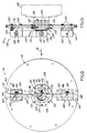
- each dampener 116 consists of a preferably disc-shaped flywheel 118 coupled to the take-up shaft 48 by a spring 120 for functioning as a vibration dampener to critically dampen stick-slip and surging thereby preventing it from adversely affecting the conveyor 34 during operation.
- the flywheel 118 is journalled for rotation by a bearing 130 on a hub 124 which has a coupling 122 that fits over the free end of the take-up shaft 48.
- the hub 124 and hence the dampener 116 is secured to the shaft 48 by a dowel 128 and cap screws 126 which extend through the hub 124 and into the end of the shaft 48 securing the hub 124 to the shaft end for rotation of the hub 124 and coupling 122 in unison with the shaft 48.
- the inner race of the bearing 130 is releasably retained on the hub 124 by a retainer nut 132 and its outer race is secured to the flywheel 118 by retainer rings 134 and cap screws 135.
- a clamp collar (not shown), such as can be constructed by splitting the coupling 122 into two halves and clamping them around the shaft 48, can be used to secure the bearing 130 and dampener 116 to the shaft 48.
- the spring 120 is secured to the hub 124 by a mounting block 136 and to the flywheel disc 118 by second and third mounting blocks 138 & 140 attached to the disc 118 radially outwardly of its center and diametrically opposed to each other.
- Spring 120 preferably extends from the second mounting block 138 to the third mounting block 140 to effectively provide a pair of springs between the hub 124 and disc 118.
- a relatively short spring 120' can be used, particularly where calculated spring thickness is small.
- either block 138 or 140 may be radially inwardly and outwardly adjustable as is shown by block 140 in phantom in FIG. 8 to accommodate springs of different lengths.
- the spring 120 To attach the spring 120 to the hub mounting block 136, it is clamped between a clamp block 137 and a pinch spacer plate 139 by a socket head screw 142 received through the plate 139 and spring 120 which is threadably engaged in a threaded bore in the block 137.
- a lock washer 141 is preferably disposed between the head of the screw 142 and the plate 139 to prevent withdrawal of the screw 142 during operation.
- mounting blocks 138 & 140 each clamp the spring 120 between a clamp block 143 and a pinch spacer plate 144 by a socket head screw 148 received through the plate 144 and spring 120 which is threadably engaged in a threaded bore 147 (FIG. 9) in the block 143.
- a lock washer 146 is preferably disposed between the head of the screw 148 and the plate 144.
- Mounting blocks 138 & 140 are both secured to the disc 118 by a plurality of spaced apart socket head screws 150.
- the spring 120 or 120' is a compound spring having a plurality of leaves of a material, such as steel, retained together (not shown).
- the spring is constructed of a plurality of leaves of, for example, 1090 blue steel or another spring steel with each leaf being approximately sixty-thousandths to one-hundred-thousandths of an inch thick for producing a spring that is resilient, long-lasting, of economical construction and having a spring rate that can be easily varied to tune the dampener by simply adding or subtracting leaves until the desired spring rate is obtained.
- a sprang 120 or 120' having the desired spring rate, k 2 , for producing a dampener 116 possessing a natural frequency, w 22 , approximately equal to the surge frequency, w s , of the conveyor apparatus 30' an appropriate number of leaves are selected and retained together for mounting in blocks 136 & 138 or additionally block 140 if a long spring 120 is used.
- the dampener 116 can be further tuned after installation on the conveyor apparatus 30' by removing or adding leaves to the spring as necessary to further reduce the amplitude of surging, if necessary.
- each chain tensioning device 56 is isolated from the chain it is associated with to prevent the chain tensioning device 56 from possibly adding an additional degree of freedom to the conveyor and increasing surging vibration amplitude.
- a conveyor apparatus without a dampener 116 installed that has a low natural frequency falling generally within the natural frequency range (usually 0-12 hertz) making it susceptible to surging and experiencing stick-slip will surge at a frequency, w s , which can be measured by a device, such as a watt-meter connected to the conveyor drive motor 50.
- a flywheel disc 118 having a mass that provides at least one-tenth the mass moment of inertia of the conveyor 34 is constructed for use in constructing the dampener 116.
- the stiffness of the spring 120 is selected to provide a dampener 116 having a natural frequency, w 22 , about equal to the surge frequency, w s , of the conveyor apparatus 30' without the dampener 116 installed.
- the conveyor apparatus 30' can be approximated as a system 152 having two degrees of freedom and modeled as such by two differential equations of motion.
- the differential equation of motion for the conveyor apparatus 30' with the dampener 116 installed is: and the equation of motion for the dampener 116 when installed on the conveyor 30' is: where:
- FIG. 10 illustrates a graph of surge amplitude, ⁇ 1 , versus the ratio of surging frequency over the conveyor natural frequency, W s / W 11 , for a surge dampener 116 having a mass moment of inertia ratio, ⁇ , of 0.1 and tuned to the surge frequency, W s , of a conveyor apparatus 30' having a surge frequency, W s , that is the same as its natural frequency, W 11 .
- FIG. 10 illustrates a graph of surge amplitude, ⁇ 1 , versus the ratio of surging frequency over the conveyor natural frequency, W s / W 11 , for a surge dampener 116 having a mass moment of inertia ratio, ⁇ , of 0.1 and tuned to the surge frequency, W s , of a conveyor apparatus 30' having a surge frequency, W s , that is the same as its natural frequency, W 11 .
- the dampener 116 provides a bandwidth of surge suppression extending on either side of the point on the graph where illustrated by the region between the dashed lines on either side of that point, where the conveyor amplitude, ⁇ 1 , is about zero or at a level which will not adversely affect operation of the conveyor apparatus 30'.
- the theory of operation of the surge dampener 116 may be further understood by summing the moments about the center, O , of the dampener 116 to obtain a differential equation of motion describing the response of the dampener 116 during operation of the conveyor 30': where:
- the mass, m f , of the flywheel disc 118 can be calculated using the following equation: where:
- equation XXVIII Arranging equation XXX in characteristic equation form, its solution is in the form: From this, the time constant, ⁇ , of the surge dampener 116 can be determined: Knowing that for a cantilevered spring, where:
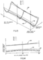
- FIG. 13 illustrates a trough-shaped, three-dimensional plot of a series of curves 154 showing the performance of dampeners 116 installed on a conveyor apparatus 30' transporting varying payloads of pallets 36 and having a wide range of flywheel mass moments of inertia coupled to springs 120 each having slightly different spring rates, k a through k d .
- Each curve is parabola-shaped in the X-Z axis, illustrating that there is an optimum flywheel mass moment of inertia that will minimize surging amplitude for each of the spring rates, k a - k d .
- plot 154 When these are determined for a conveyor apparatus 30' transporting increasing payloads of pallets 36 and combined along the Y-Z axis, they form plot 154 illustrating that there is an optimum combination of flywheel mass moment of inertia and spring rate ( k a ) that will provide the best surging vibration dampening across the wide variety of payloads that the conveyor 34 is likely to encounter during actual operation. If using such a series of curves 154 to design a dampener 116, a spring 120 having a spring rate ( k a ) that provides the best surge suppression over the widest range of loading conditions encountered by the conveyor apparatus 30' is preferably selected for use in the dampener 116.
- each curve 154 extending on either side of the lines of minimum surge amplitude 158 further illustrates the bandwidth of surge suppression of the dampener 116 where the amplitude of surging vibration is at a minimum when the dampener 116 is tuned precisely to the surge frequency, W s , or near a minimum if tuned near the surge frequency, W s , and will not affect adversely the operation of the conveyor 34.
- This bandwidth of surge suppression also applies should the surge frequency, W s , or conveyor natural frequency, W 11 , change slightly during conveyor operation, allowing a dampener 116 to suitably reduce surge amplitude, ⁇ 1 , when the conveyor 34 is encountering varying loading or other operating conditions.
- the width of the trough where the amplitude of surging, ⁇ 1 , is acceptably low corresponds roughly to the latus rectum of the curves 154 in FIG. 13 and is the bandwidth of surge suppression.
- the bandwidth is dependent upon tuning of the spring 120 and the mass of the flywheel 118. As was also illustrated in FIG. 10, the bandwidth of surge suppression is increased as the mass moment of inertia of the dampener 116 is increased, so long as the spring rate of the spring 120 is chosen to properly tune the dampener 116 to or suitably near the surge frequency, W s , of the conveyor 34.
- FIG. 14 Lines depicting minimum and maximum surge amplitude for each spring 120 (shown at the bottom and top of each side of the trough of the plot 154 in FIG. 13) are more clearly illustrated in FIG. 14.
- the spring 120 having the most optimum spring rate, k a providing the best surge suppression over the widest range of loading conditions encountered by the conveyor apparatus 30' is preferably selected for use in the dampener 116.
- the parabolic cross-section of each curve will have a greater latus rectum or flatter trough and therefore the dampener 116 when properly tuned will possess a wider bandwidth of surge suppression where the amplitude of surging is low and will not adversely affect conveyor operation. Therefore, for higher values of ⁇ , typically in the range of about 0.2 to about 0.5, the dampener 116 can be tuned less precisely to the surge frequency, W s , and still provide effective reduction of the surging amplitude.
- ⁇ in the range of about 0.1 to about 0.5 is preferably used.
- the two new natural frequencies of the conveyor system 152, W' n1 , W' n2 can be determined to operate the conveyor 34 at a speed that does not cause vibration at either natural frequency.
- the spring rate, k 2 of the dampener 116 can be varied by choosing a different spring, or adding or subtracting spring leaves to "tune" the system 152 to a slightly different set of natural frequencies and eliminate the vibration.
- any tuning of this nature must be carefully done to avoid tuning the dampener 116 to a frequency so far away from the surge frequency, W s , that surging begins to affect operation of the conveyor apparatus 30'.
- W s Prior to installing a dampener 116 on a conveyor experiencing surging, its surge frequency, W s , is determined preferably by connecting a watt-meter to the drive motor 50 of the conveyor to measure the frequency of power variation in the motor 50 caused by fluctuating torque applied to the motor 50 by the chains 38, 40 during surging. As is represented in a plot shown in FIG. 15 of drive motor power consumption over time, t , in a conveyor experiencing surging, the frequency of the power fluctuations of the drive motor 50 corresponds to the frequency of surging, W s . Since the surge frequency, W s , remains generally the same for all conveyor speeds after surging has begun, although it may decrease slightly as conveyor speed is decreased, the speed of the conveyor need simply be reduced until surging occurs to determine W s .
- the mass moment of inertia, I 2 , of the flywheel disc 118 is multiplied by the inertia ratio, ⁇ .
- ⁇ is selected to be at least 0.1 and more preferably about 0.2 to produce a dampener 116 that, when properly tuned, has a flywheel 118 possessing a large enough mass moment of inertia to provide a sufficiently wide bandwidth of surge suppression for preventing surging under the wide variety of conveyor loading and operating conditions typically encountered by the conveyor 34.
- ⁇ can be as high as 1 when determining the mass moment of inertia, I 2 , of the flywheel 118, it is generally impractical to use such a high inertia ratio because it typically would result in the use of a massive flywheel of unmanageable size.
- the mass, m f , of the flywheel disc 118 can be calculated once the mass moment of inertia, I 2 , of the disc 118 has been determined knowing the following relationships: where:
- ⁇ is determined using equation XXIV and the two new natural frequencies of the conveyor system, W' n1 , W' n2 , are determined to ensure that the conveyor apparatus 30' is not operated at a speed that results in vibration at either new natural frequency.
- a somewhat lower inertia ratio, ⁇ may be selected if a less massive flywheel 118 is desired.
- the conveyor apparatus 30' is constructed with two chains 38, 40 and a split take-up shaft 48 having an idle sprocket 44 on each shaft section 62, 64.
- the conveyor 34 is 42,6 m (one hundred forty feet) long having a chain loop length of approximately 85 m (two hundred eighty feet) and possessing a maximum payload capacity of 8164 kg (18,000 lbs).
- Each chain 38, 40 is a three-strand chain having an average cross-sectional area of 2.95 cm 2 (0.458 in. 2 ) and a modulus of elasticity of 2 x 10 5 N/mm 2 (30 * 10 6 psi).
- Each chain 38, 40 is carried out by an idle sprocket 44 having a diameter of 305 mm (twelve inches).
- the coefficient of friction, ⁇ between each chain 38, 40 and the guide rails and each chain 38, 40 and the pallets 36 is 0.1 and the inertia ratio, ⁇ , is specified to be 0.25.
- the flywheel disc 118 of the dampener 116 is to have a diameter of 760 mm (thirty inches).
- the spring 120 is to have a length of 711 mm (twenty-eight inches), a width of 50 mm (two inches) and an effective length, r' , of 177 mm (seven inches).
- the conveyor 34 is surging at 10.7 hertz (67.2 rad/sec).
- the mass of the flywheel disc is:
- the weight of the disc is: .
- the thickness of the disc is:
- the linear spring rate, k 2linear can be calculated:
- the thickness, t spring of the spring 120 can be determined using equation XLV: Should a longer spring 120 be used, the thickness of the spring, t spring , would be one-half the above calculated value or:
- the two new natural frequencies of the conveyor and dampener system 152 can be found solving equation XXXVIII above.
- a pair of dampeners 116 each having a flywheel 118 of about 38 mm (11 ⁇ 2 inches) thick and 762 mm (thirty inches) in diameter with a weight of about (130 kg (287.8 lbs) and a long spring 120 slightly greater than one-half inch thick with a spring rate of 4.29 x 10 7 Nmm/rad (3.8 * 10 5 in ⁇ lbf/rad), are attached to the split take-up shaft 48, with a dampener 116 attached to one end of each shaft section of the split take-up shaft 48 of the conveyor of this example for preventing stick-slip and surging vibration from adversely affecting operation of the conveyor.
- the conveyor apparatus 30' is constructed with two chains 38, 40 and a solid take-up shaft 48.
- the conveyor 34 is 33 m (one hundred ten feet) long having a chain loop length of approximately 67 m (two hundred twenty feet) and possessing a maximum payload capacity of 5450 kg (12,000 lbs).
- Each chain 38, 40 is a 4-strand chain having an average cross-sectional area of 3.9 cm 2 (0.61 in. 2 ) and a modulus of elasticity of 2 x 10 5 N/mm 2 (30 * 10 6 psi).
- Each chain 38, 40 is carried by an idle sprocket 44 having a diameter of 305 mm (twelve inches).
- the coefficient of friction, ⁇ between each chain 38, 40 and the guide rails and each chain 38, 40 and the pallets 36 is 0.1 and the inertia ratio, ⁇ , is specified to be 0.2.
- the flywheel disc 118 of the dampener 116 is to have a diameter of 305 mm (thirty inches).
- the spring 120 is to have a length of 711 mm (twenty-eight inches), and width of 50,8 mm (two inches) and an effective length, r ', of 203 mm (eight inches).
- the conveyor 34 is surging at 8.5 hertz (53.4 rad/sec).
- the mass of the flywheel disc is:
- the weight of the disc is:
- the thickness of the disc is:
- the linear spring rate, k 2linear can be calculated:
- the thickness, t spring of the spring 120 can be determined using equation XLV: Should a longer spring 120 be used, the thickness of the spring, t spring , would be one-half the above calculated value or:
- the two new natural frequencies of the conveyor and dampener system 152 can be found solving equation XXXVIII above.
- a single dampener 116 having a flywheel 118 of about 38.1 mm (11 ⁇ 2 inches) thick and thirty inches in diameter with a weight of about 139.3 kg (307.2 lbs), and a spring 120 slight than one-half inch thick with a spring rate of 288 Nmm/rad (2.55 * 10 5 in ⁇ lbf/rad) is attached to one end of the solid take-up shaft 48 of the conveyor of this example for preventing stick-slip and surging vibration from adversely affecting operation of the conveyor.
- the conveyor 34 is driven by the drive motor 50 to transport the pallets 36 along the length of the conveyor apparatus 30'.
- friction conditions between the chains 38, 40 and guide rails cause that portion of each chain 38, 40 nearest the drive sprockets 42 to move along the guide rails while the chain links disposed away from the sprocket 42 remain stationary leading to the formation of stick-slip.
- each chain 38, 40 As the chains 38, 40 begin to alternately stick and slip, the changes in the amplitude of the chain velocity of each chain 38, 40 are transmitted through each spring 120 of each dampener 116 to its flywheel 118 where the stick-slip vibration is dampened by the inertia produced by each flywheel 118 enabling a relatively constant chain velocity to be maintained.
- the amplitude, ⁇ 1 of conveyor surging decreases over time as each dampener 116 critically damps stick-slip to prevent stick-slip from exciting the chains 38, 40 into surging and dampens the surging vibrations of the chains 38, 40.
Landscapes
- Engineering & Computer Science (AREA)
- Mechanical Engineering (AREA)
- Control Of Conveyors (AREA)
- Escalators And Moving Walkways (AREA)
Applications Claiming Priority (2)
| Application Number | Priority Date | Filing Date | Title |
|---|---|---|---|
| US08/178,031 US5388685A (en) | 1994-01-06 | 1994-01-06 | Endless conveyor |
| US178031 | 1994-01-06 |
Publications (2)
| Publication Number | Publication Date |
|---|---|
| EP0664261A1 EP0664261A1 (en) | 1995-07-26 |
| EP0664261B1 true EP0664261B1 (en) | 1999-01-20 |
Family
ID=22650891
Family Applications (1)
| Application Number | Title | Priority Date | Filing Date |
|---|---|---|---|
| EP94116333A Expired - Lifetime EP0664261B1 (en) | 1994-01-06 | 1994-10-17 | Endless conveyor |
Country Status (5)
| Country | Link |
|---|---|
| US (1) | US5388685A (es) |
| EP (1) | EP0664261B1 (es) |
| CA (1) | CA2133905C (es) |
| DE (1) | DE69416102T2 (es) |
| ES (1) | ES2127331T3 (es) |
Cited By (1)
| Publication number | Priority date | Publication date | Assignee | Title |
|---|---|---|---|---|
| EP2314528A2 (de) | 2009-10-23 | 2011-04-27 | Robert Bosch GmbH | Kettenförderer mit Dämpfungsvorrichtung |
Families Citing this family (14)
| Publication number | Priority date | Publication date | Assignee | Title |
|---|---|---|---|---|
| US5465826A (en) * | 1994-02-24 | 1995-11-14 | Valiant Machine & Tool, Inc. | Conveyor system |
| US6115962A (en) * | 1994-03-31 | 2000-09-12 | Southpac Trust International, Inc. | Sleeve for covering a flower pot |
| CA2370416C (en) * | 2001-02-07 | 2010-01-26 | Denipro Ag | Conveyor system |
| US6997304B2 (en) * | 2002-12-23 | 2006-02-14 | Thomas Timothy N | Accumulating conveyor |
| US7195115B2 (en) * | 2005-07-15 | 2007-03-27 | Laitram, L.L.C. | Modular-belt conveyors with variable-speed drive motors |
| WO2007092882A2 (en) * | 2006-02-07 | 2007-08-16 | Thermodrive Llc | Conveyor with edge guides |
| US8078303B2 (en) * | 2007-07-03 | 2011-12-13 | Southwire Company | Electronic supervisor |
| ES2294972B1 (es) * | 2007-09-05 | 2009-04-01 | Thyssenkrupp Elevator Innovation Center, S.A. | Sistema de curva de volteo para sistema de transporte por cadena. |
| CN105235942B (zh) * | 2015-10-19 | 2017-05-17 | 张家港市中悦冶金设备科技有限公司 | 一种与管材加工设备相配合的送料平台 |
| CN110817337B (zh) * | 2019-11-28 | 2021-06-22 | 东台市鑫富达机械有限公司 | 一种玉米果穗重量称重后输送带 |
| CN112454315B (zh) * | 2020-12-08 | 2022-05-17 | 嘉兴量创科技有限公司 | 一种过滤框整齐排列调节控制装置 |
| CN112456036A (zh) * | 2020-12-11 | 2021-03-09 | 四川德胜集团钒钛有限公司 | 一种重型板式给料机下支撑装置 |
| CN114506628B (zh) * | 2022-03-15 | 2023-07-07 | 东风柳州汽车有限公司 | 一种涂装车间防爬行输送机构 |
| CN115848943A (zh) * | 2022-12-05 | 2023-03-28 | 中煤科工集团上海有限公司 | 一种带式输送机优化运行控制方法 |
Family Cites Families (9)
| Publication number | Priority date | Publication date | Assignee | Title |
|---|---|---|---|---|
| US2932381A (en) * | 1958-04-23 | 1960-04-12 | Morgan Construction Co | Torque equalizer |
| US4037334A (en) * | 1976-05-21 | 1977-07-26 | Deere & Company | Drive means for an elevating scraper elevator |
| US4512460A (en) * | 1983-03-30 | 1985-04-23 | Glasstech, Inc. | Glass sheet roller conveyor including antifriction drive chain |
| US4825999A (en) * | 1987-05-21 | 1989-05-02 | Cannon Usa, Inc. | Chain drive apparatus |
| SU1488216A1 (ru) * | 1987-06-09 | 1989-06-23 | Le I Textilnoi | Цепной конвейер |
| US4934515A (en) * | 1988-08-16 | 1990-06-19 | Litton Industrial Automation Systems, Inc. | Endless accumulating conveyor |
| US5188219A (en) * | 1989-03-31 | 1993-02-23 | Takayasu Mitsumoto | Horizontal rotary transfer apparatus |
| US5070996A (en) * | 1989-09-15 | 1991-12-10 | Kurt Schwaemmle | Chain conveyor and pallet |
| US5029691A (en) * | 1989-09-15 | 1991-07-09 | Fein Ronald K E | Chain conveyor and pallet |
-
1994
- 1994-01-06 US US08/178,031 patent/US5388685A/en not_active Expired - Fee Related
- 1994-10-17 EP EP94116333A patent/EP0664261B1/en not_active Expired - Lifetime
- 1994-10-17 DE DE69416102T patent/DE69416102T2/de not_active Expired - Fee Related
- 1994-10-17 ES ES94116333T patent/ES2127331T3/es not_active Expired - Lifetime
- 1994-10-20 CA CA002133905A patent/CA2133905C/en not_active Expired - Fee Related
Cited By (2)
| Publication number | Priority date | Publication date | Assignee | Title |
|---|---|---|---|---|
| EP2314528A2 (de) | 2009-10-23 | 2011-04-27 | Robert Bosch GmbH | Kettenförderer mit Dämpfungsvorrichtung |
| DE102009050488A1 (de) | 2009-10-23 | 2011-04-28 | Robert Bosch Gmbh | Kettenförderer mit Dämpfungsvorrichtung |
Also Published As
| Publication number | Publication date |
|---|---|
| CA2133905A1 (en) | 1995-07-07 |
| US5388685A (en) | 1995-02-14 |
| ES2127331T3 (es) | 1999-04-16 |
| DE69416102D1 (de) | 1999-03-04 |
| CA2133905C (en) | 2005-01-11 |
| DE69416102T2 (de) | 1999-09-09 |
| EP0664261A1 (en) | 1995-07-26 |
Similar Documents
| Publication | Publication Date | Title |
|---|---|---|
| EP0664261B1 (en) | Endless conveyor | |
| US6079548A (en) | Differential impulse conveyor and method | |
| EP2998245B1 (en) | Vibratory conveyor | |
| CA2204682C (en) | Excited base conveyor system | |
| US4372440A (en) | End shaft mount for conveyor | |
| EP0774595B1 (en) | Nested damping device with relative motion | |
| WO1997041052A1 (en) | Vertical belt conveyor system | |
| US3528541A (en) | Balanced oscillating conveyor | |
| US5586639A (en) | Powered roller conveyer for light loads | |
| US5239886A (en) | Stability high gain and dynamic stiffness servo axis drive system and method | |
| KR102714594B1 (ko) | 스트립 버퍼링용 페스투너 및 스트립 버퍼링 방법 | |
| US4165863A (en) | Hoist system | |
| US5205190A (en) | Stability high gain and dynamic stiffness servo axis drive system and method | |
| EP3686456A1 (en) | Pedestrian conveyor mass damper to reduce step vibration | |
| SE466865B (sv) | Kuggremstransmission, i synnerhet foer foerbraenningsmotorer | |
| RU2258658C1 (ru) | Конвейер с подвесной лентой | |
| US3238798A (en) | Controls for vibratory apparatus | |
| WO2001038205A1 (en) | Material transfer system | |
| Choi et al. | Transverse vibrations of a roller chain drive with a tensioner | |
| JPH05319537A (ja) | 振動コンベヤ | |
| NL8200701A (nl) | Triltransportinrichting. | |
| WO2003104682A1 (en) | Self-tensioning motor mount for drive assembly | |
| US3865231A (en) | Roller band mechanism and suspension system for oscillating conveyors | |
| CN223792353U (zh) | 一种防震稳定型输送辊筒 | |
| CN223509025U (zh) | 一种用于滚筒链条的紧固装置 |
Legal Events
| Date | Code | Title | Description |
|---|---|---|---|
| PUAI | Public reference made under article 153(3) epc to a published international application that has entered the european phase |
Free format text: ORIGINAL CODE: 0009012 |
|
| AK | Designated contracting states |
Kind code of ref document: A1 Designated state(s): DE ES FR GB SE |
|
| 17P | Request for examination filed |
Effective date: 19951107 |
|
| 17Q | First examination report despatched |
Effective date: 19961018 |
|
| GRAG | Despatch of communication of intention to grant |
Free format text: ORIGINAL CODE: EPIDOS AGRA |
|
| GRAG | Despatch of communication of intention to grant |
Free format text: ORIGINAL CODE: EPIDOS AGRA |
|
| GRAG | Despatch of communication of intention to grant |
Free format text: ORIGINAL CODE: EPIDOS AGRA |
|
| GRAH | Despatch of communication of intention to grant a patent |
Free format text: ORIGINAL CODE: EPIDOS IGRA |
|
| RAP1 | Party data changed (applicant data changed or rights of an application transferred) |
Owner name: UNOVA INDUSTRIAL AUTOMATION SYSTEMS, INC. |
|
| GRAH | Despatch of communication of intention to grant a patent |
Free format text: ORIGINAL CODE: EPIDOS IGRA |
|
| GRAA | (expected) grant |
Free format text: ORIGINAL CODE: 0009210 |
|
| AK | Designated contracting states |
Kind code of ref document: B1 Designated state(s): DE ES FR GB SE |
|
| ET | Fr: translation filed | ||
| REF | Corresponds to: |
Ref document number: 69416102 Country of ref document: DE Date of ref document: 19990304 |
|
| REG | Reference to a national code |
Ref country code: ES Ref legal event code: FG2A Ref document number: 2127331 Country of ref document: ES Kind code of ref document: T3 |
|
| PG25 | Lapsed in a contracting state [announced via postgrant information from national office to epo] |
Ref country code: DE Free format text: LAPSE BECAUSE OF FAILURE TO SUBMIT A TRANSLATION OF THE DESCRIPTION OR TO PAY THE FEE WITHIN THE PRESCRIBED TIME-LIMIT Effective date: 19990421 |
|
| PLBE | No opposition filed within time limit |
Free format text: ORIGINAL CODE: 0009261 |
|
| STAA | Information on the status of an ep patent application or granted ep patent |
Free format text: STATUS: NO OPPOSITION FILED WITHIN TIME LIMIT |
|
| 26N | No opposition filed | ||
| PGFP | Annual fee paid to national office [announced via postgrant information from national office to epo] |
Ref country code: FR Payment date: 20000918 Year of fee payment: 7 |
|
| PGFP | Annual fee paid to national office [announced via postgrant information from national office to epo] |
Ref country code: GB Payment date: 20000921 Year of fee payment: 7 |
|
| PGFP | Annual fee paid to national office [announced via postgrant information from national office to epo] |
Ref country code: SE Payment date: 20000928 Year of fee payment: 7 |
|
| PGFP | Annual fee paid to national office [announced via postgrant information from national office to epo] |
Ref country code: ES Payment date: 20001018 Year of fee payment: 7 |
|
| PGFP | Annual fee paid to national office [announced via postgrant information from national office to epo] |
Ref country code: DE Payment date: 20001229 Year of fee payment: 7 |
|
| PG25 | Lapsed in a contracting state [announced via postgrant information from national office to epo] |
Ref country code: GB Free format text: LAPSE BECAUSE OF NON-PAYMENT OF DUE FEES Effective date: 20011017 |
|
| PG25 | Lapsed in a contracting state [announced via postgrant information from national office to epo] |
Ref country code: SE Free format text: LAPSE BECAUSE OF NON-PAYMENT OF DUE FEES Effective date: 20011018 Ref country code: ES Free format text: LAPSE BECAUSE OF NON-PAYMENT OF DUE FEES Effective date: 20011018 |
|
| REG | Reference to a national code |
Ref country code: GB Ref legal event code: IF02 |
|
| EUG | Se: european patent has lapsed |
Ref document number: 94116333.9 |
|
| GBPC | Gb: european patent ceased through non-payment of renewal fee |
Effective date: 20011017 |
|
| PG25 | Lapsed in a contracting state [announced via postgrant information from national office to epo] |
Ref country code: FR Free format text: LAPSE BECAUSE OF NON-PAYMENT OF DUE FEES Effective date: 20020628 |
|
| REG | Reference to a national code |
Ref country code: FR Ref legal event code: ST |
|
| REG | Reference to a national code |
Ref country code: ES Ref legal event code: FD2A Effective date: 20021113 |