EP0664184B1 - Rotule à haute résistance mécanique et procédé de fabrication - Google Patents
Rotule à haute résistance mécanique et procédé de fabrication Download PDFInfo
- Publication number
- EP0664184B1 EP0664184B1 EP95400004A EP95400004A EP0664184B1 EP 0664184 B1 EP0664184 B1 EP 0664184B1 EP 95400004 A EP95400004 A EP 95400004A EP 95400004 A EP95400004 A EP 95400004A EP 0664184 B1 EP0664184 B1 EP 0664184B1
- Authority
- EP
- European Patent Office
- Prior art keywords
- cage
- ring
- spherical element
- process according
- ball joint
- Prior art date
- Legal status (The legal status is an assumption and is not a legal conclusion. Google has not performed a legal analysis and makes no representation as to the accuracy of the status listed.)
- Expired - Lifetime
Links
- 238000004519 manufacturing process Methods 0.000 title claims description 14
- 238000000034 method Methods 0.000 title claims description 6
- 239000000463 material Substances 0.000 claims abstract description 13
- 238000005299 abrasion Methods 0.000 claims abstract description 5
- 229910000617 Mangalloy Inorganic materials 0.000 claims abstract description 4
- 229910000831 Steel Inorganic materials 0.000 claims abstract description 3
- 239000010959 steel Substances 0.000 claims abstract description 3
- 239000011162 core material Substances 0.000 claims abstract 4
- 238000003466 welding Methods 0.000 claims description 12
- 238000003754 machining Methods 0.000 claims description 7
- 230000000295 complement effect Effects 0.000 claims description 5
- 238000005520 cutting process Methods 0.000 claims description 5
- 238000007493 shaping process Methods 0.000 claims description 3
- PWHULOQIROXLJO-UHFFFAOYSA-N Manganese Chemical compound [Mn] PWHULOQIROXLJO-UHFFFAOYSA-N 0.000 claims description 2
- 229910018487 Ni—Cr Inorganic materials 0.000 claims description 2
- VNNRSPGTAMTISX-UHFFFAOYSA-N chromium nickel Chemical compound [Cr].[Ni] VNNRSPGTAMTISX-UHFFFAOYSA-N 0.000 claims description 2
- 238000010891 electric arc Methods 0.000 claims description 2
- 238000005242 forging Methods 0.000 claims description 2
- 230000006698 induction Effects 0.000 claims description 2
- 229910052748 manganese Inorganic materials 0.000 claims description 2
- 239000011572 manganese Substances 0.000 claims description 2
- OKTJSMMVPCPJKN-UHFFFAOYSA-N Carbon Chemical compound [C] OKTJSMMVPCPJKN-UHFFFAOYSA-N 0.000 claims 1
- 229910052799 carbon Inorganic materials 0.000 claims 1
- 230000001747 exhibiting effect Effects 0.000 claims 1
- 239000011261 inert gas Substances 0.000 claims 1
- 230000035939 shock Effects 0.000 description 5
- 210000004417 patella Anatomy 0.000 description 3
- 238000005461 lubrication Methods 0.000 description 2
- 239000011159 matrix material Substances 0.000 description 2
- 238000010521 absorption reaction Methods 0.000 description 1
- 230000003042 antagnostic effect Effects 0.000 description 1
- 238000005259 measurement Methods 0.000 description 1
- 230000007935 neutral effect Effects 0.000 description 1
- 229910000679 solder Inorganic materials 0.000 description 1
Images
Classifications
-
- F—MECHANICAL ENGINEERING; LIGHTING; HEATING; WEAPONS; BLASTING
- F16—ENGINEERING ELEMENTS AND UNITS; GENERAL MEASURES FOR PRODUCING AND MAINTAINING EFFECTIVE FUNCTIONING OF MACHINES OR INSTALLATIONS; THERMAL INSULATION IN GENERAL
- F16C—SHAFTS; FLEXIBLE SHAFTS; ELEMENTS OR CRANKSHAFT MECHANISMS; ROTARY BODIES OTHER THAN GEARING ELEMENTS; BEARINGS
- F16C23/00—Bearings for exclusively rotary movement adjustable for aligning or positioning
- F16C23/02—Sliding-contact bearings
- F16C23/04—Sliding-contact bearings self-adjusting
- F16C23/043—Sliding-contact bearings self-adjusting with spherical surfaces, e.g. spherical plain bearings
- F16C23/045—Sliding-contact bearings self-adjusting with spherical surfaces, e.g. spherical plain bearings for radial load mainly, e.g. radial spherical plain bearings
-
- B—PERFORMING OPERATIONS; TRANSPORTING
- B23—MACHINE TOOLS; METAL-WORKING NOT OTHERWISE PROVIDED FOR
- B23P—METAL-WORKING NOT OTHERWISE PROVIDED FOR; COMBINED OPERATIONS; UNIVERSAL MACHINE TOOLS
- B23P15/00—Making specific metal objects by operations not covered by a single other subclass or a group in this subclass
- B23P15/003—Making specific metal objects by operations not covered by a single other subclass or a group in this subclass bearings
-
- F—MECHANICAL ENGINEERING; LIGHTING; HEATING; WEAPONS; BLASTING
- F16—ENGINEERING ELEMENTS AND UNITS; GENERAL MEASURES FOR PRODUCING AND MAINTAINING EFFECTIVE FUNCTIONING OF MACHINES OR INSTALLATIONS; THERMAL INSULATION IN GENERAL
- F16C—SHAFTS; FLEXIBLE SHAFTS; ELEMENTS OR CRANKSHAFT MECHANISMS; ROTARY BODIES OTHER THAN GEARING ELEMENTS; BEARINGS
- F16C11/00—Pivots; Pivotal connections
- F16C11/04—Pivotal connections
- F16C11/06—Ball-joints; Other joints having more than one degree of angular freedom, i.e. universal joints
- F16C11/0604—Construction of the male part
-
- F—MECHANICAL ENGINEERING; LIGHTING; HEATING; WEAPONS; BLASTING
- F16—ENGINEERING ELEMENTS AND UNITS; GENERAL MEASURES FOR PRODUCING AND MAINTAINING EFFECTIVE FUNCTIONING OF MACHINES OR INSTALLATIONS; THERMAL INSULATION IN GENERAL
- F16C—SHAFTS; FLEXIBLE SHAFTS; ELEMENTS OR CRANKSHAFT MECHANISMS; ROTARY BODIES OTHER THAN GEARING ELEMENTS; BEARINGS
- F16C11/00—Pivots; Pivotal connections
- F16C11/04—Pivotal connections
- F16C11/06—Ball-joints; Other joints having more than one degree of angular freedom, i.e. universal joints
- F16C11/0614—Ball-joints; Other joints having more than one degree of angular freedom, i.e. universal joints the female part of the joint being open on two sides
-
- B—PERFORMING OPERATIONS; TRANSPORTING
- B23—MACHINE TOOLS; METAL-WORKING NOT OTHERWISE PROVIDED FOR
- B23P—METAL-WORKING NOT OTHERWISE PROVIDED FOR; COMBINED OPERATIONS; UNIVERSAL MACHINE TOOLS
- B23P2700/00—Indexing scheme relating to the articles being treated, e.g. manufactured, repaired, assembled, connected or other operations covered in the subgroups
- B23P2700/11—Joints, e.g. ball joints, universal joints
-
- Y—GENERAL TAGGING OF NEW TECHNOLOGICAL DEVELOPMENTS; GENERAL TAGGING OF CROSS-SECTIONAL TECHNOLOGIES SPANNING OVER SEVERAL SECTIONS OF THE IPC; TECHNICAL SUBJECTS COVERED BY FORMER USPC CROSS-REFERENCE ART COLLECTIONS [XRACs] AND DIGESTS
- Y10—TECHNICAL SUBJECTS COVERED BY FORMER USPC
- Y10T—TECHNICAL SUBJECTS COVERED BY FORMER US CLASSIFICATION
- Y10T29/00—Metal working
- Y10T29/49—Method of mechanical manufacture
- Y10T29/49636—Process for making bearing or component thereof
- Y10T29/49643—Rotary bearing
- Y10T29/49647—Plain bearing
- Y10T29/49648—Self-adjusting or self-aligning, including ball and socket type, bearing and component making
- Y10T29/4965—Deforming socket to secure ball
- Y10T29/49652—Die-press shaping
-
- Y—GENERAL TAGGING OF NEW TECHNOLOGICAL DEVELOPMENTS; GENERAL TAGGING OF CROSS-SECTIONAL TECHNOLOGIES SPANNING OVER SEVERAL SECTIONS OF THE IPC; TECHNICAL SUBJECTS COVERED BY FORMER USPC CROSS-REFERENCE ART COLLECTIONS [XRACs] AND DIGESTS
- Y10—TECHNICAL SUBJECTS COVERED BY FORMER USPC
- Y10T—TECHNICAL SUBJECTS COVERED BY FORMER US CLASSIFICATION
- Y10T29/00—Metal working
- Y10T29/49—Method of mechanical manufacture
- Y10T29/49636—Process for making bearing or component thereof
- Y10T29/49643—Rotary bearing
- Y10T29/49647—Plain bearing
- Y10T29/49648—Self-adjusting or self-aligning, including ball and socket type, bearing and component making
- Y10T29/49657—Socket making
-
- Y—GENERAL TAGGING OF NEW TECHNOLOGICAL DEVELOPMENTS; GENERAL TAGGING OF CROSS-SECTIONAL TECHNOLOGIES SPANNING OVER SEVERAL SECTIONS OF THE IPC; TECHNICAL SUBJECTS COVERED BY FORMER USPC CROSS-REFERENCE ART COLLECTIONS [XRACs] AND DIGESTS
- Y10—TECHNICAL SUBJECTS COVERED BY FORMER USPC
- Y10T—TECHNICAL SUBJECTS COVERED BY FORMER US CLASSIFICATION
- Y10T29/00—Metal working
- Y10T29/49—Method of mechanical manufacture
- Y10T29/49826—Assembling or joining
- Y10T29/49833—Punching, piercing or reaming part by surface of second part
-
- Y—GENERAL TAGGING OF NEW TECHNOLOGICAL DEVELOPMENTS; GENERAL TAGGING OF CROSS-SECTIONAL TECHNOLOGIES SPANNING OVER SEVERAL SECTIONS OF THE IPC; TECHNICAL SUBJECTS COVERED BY FORMER USPC CROSS-REFERENCE ART COLLECTIONS [XRACs] AND DIGESTS
- Y10—TECHNICAL SUBJECTS COVERED BY FORMER USPC
- Y10T—TECHNICAL SUBJECTS COVERED BY FORMER US CLASSIFICATION
- Y10T29/00—Metal working
- Y10T29/49—Method of mechanical manufacture
- Y10T29/49826—Assembling or joining
- Y10T29/4984—Retaining clearance for motion between assembled parts
- Y10T29/49845—Retaining clearance for motion between assembled parts by deforming interlock
- Y10T29/49853—Retaining clearance for motion between assembled parts by deforming interlock of sphere, i.e., ball, in socket
Definitions
- the present invention relates to a manufacturing process a high ball joint mechanical resistance and in particular abrasion, impact and crushing, of the ball joint type by extension of his cage.
- ball cages made of a material treated with heart of high hardness (more than 60 H.R.C.), including the spherical part of the same material and treatment is received in the cage by opening it on a radius by means of a shock on the lateral face.
- these ball joints are fragile, being prone to cage fractures.
- any interruption of lubrication, especially for a exposure to shock and crushing makes these ball joints very vulnerable.
- the invention aims to remedy these drawbacks.
- a method is proposed manufacturing a high mechanical resistance ball joint and particularly abrasion, shock and crushing, consistent to claim 1.
- Materials constituting the spherical element are advantageously shades known as the designation Z 30C 13T or 42 CD 4T.
- a high resistance ball joint is thus obtained mechanical and abrasion, the manganese-based element absorbing shock and crushing energy and self-locking on the surface against that of the other element to allow self-lubrication of the joint.
- This self-hardening increases as and measurement of the stress until reaching the hardness of the antagonistic surface of the spherical element.
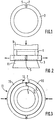
- the ball joint according to the invention is of the type comprising an element spherical 1 or ball itself inserted in movement free rotating in a circular ring or cage complementary 3.
- the ball joint is intended to be mounted classic way on a shaft by its bore part.
- the spherical element 1 is typically machined from Z 30C 13T steel pretreated to 882-1029N / mm 2 (90-105 kg / mm 2 ) to the core and its surface is heat treated by induction at very high hardness , approximately 1862N / mm 2 (190 kg / mm 2 ) or approximately 55 HRC) over a thickness of 2 to 3 mm. This item does not undergo any other treatment.
- the ring 3 is the result of forging and machining from an austenitic manganese steel of the above-mentioned grade Z 120M 12.
- the inner surface, receiving the spherical element, is slightly pre-nutted at a hardness of 38 to 40 HRC over a depth of 3-5 tenths of mm.
- the dimensions of this ring are slightly larger than those of the final ring. Indeed, its inner circumference has an additional length e , of 1.4 mm, equal to the width of the blade of the tool used for the subsequent cutting operation. This length e can vary at most by 1 mm depending on the dimensions of the ball joint, from 100 to 300 mm in diameter, in direct proportion to the diameter. Similarly, its thickness is slightly greater, 1 to 2 mm, to allow the subsequent exterior finishing step (machining) to the final dimension.
- the first typical operation of the manufacturing according to the invention is a parting off of the ring along a radius, by a conventional cutting tool, for example a rotary cutting disc with width equal to 1.4 mm.
- the ring is thus cut into 5 and a chamfer 7 is then made at the top of the slot 5 of the cutting-off as shown in FIG. 1.
- This chamfer is formed over the entire width of the ring, as well as on its sides up to a distance of about 1 mm (closest) to the bottom surface area treated and to a depth substantially equal to the half the thickness of it.
- the applicator punch 9 has a suitable (complementary) shape side faces of the ring, and a base or matrix tapered lower 11, tapered upward, the section corresponds to the lateral opening of the ring for that it is engaged at its upper part, and angle relatively small cone.
- the ring is therefore engaged by one of its side openings on the matrix 11 and the element spherical, placed on the other opening of the ring, receives on its upper face the applicator punch 9 of the hurry.
- the punch is applied by force towards the base, the spherical element remaining in a layout parallel to the ring. This extends under the action of cone and as soon as it has moved away enough, the element spherical penetrates by itself, under the elasticity of the ring, in this one.
- the patella is now assembled and can undergo the third operation of linking the cut edges of the Ring. This consists of a weld chamfer level 7 of the ring slot.
- the patella is introduced into a template 13 for placing in the shape of the ring to its final size of service.
- This template has two substantially semi-circular jaws 15, complementary to the ring in its shape tightened and articulated at the lower level. These jaws forcefully applied to each other until complete tightening of the ring with application one on the other of the cutting edges, leaving an opening upper 17 allowing said operation to be carried out welding.
- This is carried out conventionally under electric arc (under neutral gas between electrodes) with material input by a welding material wire suitable, for example based on nickel-chromium, for a temperature below 250 ° C so as not to affect the surface areas treated.
- the solder cover layer is made in the same material as the ring.
- the patella is then completed.
- the assembly at instead of being carried out flat as described above, can the being with the spherical element applied perpendicularly to the ring, held by part of its circumference on an appropriately shaped applicator punch, while the ring opens on a wide open lower base in its internal part (sleeve type receiving the faces side of the ring.
- the formatting template can be conical internal bore shape receiving the ball joint force, in abutment at its final tightened position.
Landscapes
- Engineering & Computer Science (AREA)
- General Engineering & Computer Science (AREA)
- Mechanical Engineering (AREA)
- Rolling Contact Bearings (AREA)
- Pivots And Pivotal Connections (AREA)
- Forging (AREA)
- Pens And Brushes (AREA)
- Crushing And Grinding (AREA)
- Heat Treatment Of Articles (AREA)
- Ceramic Products (AREA)
Applications Claiming Priority (2)
| Application Number | Priority Date | Filing Date | Title |
|---|---|---|---|
| FR9400772A FR2715338B1 (fr) | 1994-01-25 | 1994-01-25 | Rotule à haute résistance mécanique et procédé de fabrication. |
| FR9400772 | 1994-01-25 |
Publications (2)
| Publication Number | Publication Date |
|---|---|
| EP0664184A1 EP0664184A1 (fr) | 1995-07-26 |
| EP0664184B1 true EP0664184B1 (fr) | 1999-09-15 |
Family
ID=9459364
Family Applications (1)
| Application Number | Title | Priority Date | Filing Date |
|---|---|---|---|
| EP95400004A Expired - Lifetime EP0664184B1 (fr) | 1994-01-25 | 1995-01-03 | Rotule à haute résistance mécanique et procédé de fabrication |
Country Status (9)
| Country | Link |
|---|---|
| US (1) | US5735048A (da) |
| EP (1) | EP0664184B1 (da) |
| JP (1) | JPH07208449A (da) |
| AT (1) | ATE184533T1 (da) |
| DE (1) | DE69512096T2 (da) |
| DK (1) | DK0664184T3 (da) |
| ES (1) | ES2139852T3 (da) |
| FI (1) | FI116744B (da) |
| FR (1) | FR2715338B1 (da) |
Families Citing this family (15)
| Publication number | Priority date | Publication date | Assignee | Title |
|---|---|---|---|---|
| EP0865551B1 (de) * | 1995-12-09 | 1999-05-26 | DANZ, Robert | Halterung fur die biegemomentfreie lagerung von glastafeln |
| FR2770881B1 (fr) | 1997-11-10 | 2000-01-28 | Int Des Applic Tech Mangachoc | Procede d'assemblage d'un arbre et d'une rotule a haute resistance mecanique, et ensemble d'arbre et rotule obtenu |
| JP3648985B2 (ja) * | 1998-06-30 | 2005-05-18 | 日本精工株式会社 | ケージ型保持器付きボールねじ |
| NL1015724C2 (nl) * | 2000-07-14 | 2002-01-15 | Skf Eng & Res Centre Bv | Werkwijze voor het samenstellen van een dubbelrijig hoekcontact-wentelelement-lagereenheid, en eenheid vervaardigd volgens die werkwijze. |
| WO2009056159A1 (en) * | 2007-11-02 | 2009-05-07 | Aktiebolaget Skf | Combination of bearing component and sensor |
| CN104600647A (zh) * | 2015-01-13 | 2015-05-06 | 江苏捷凯电力器材有限公司 | 一种高强度轻量化电力连接金具及成形方法 |
| CN105729071B (zh) * | 2016-04-27 | 2018-02-06 | 安顺市虹翼特种钢球制造有限公司 | 一种高精度奥氏体不锈钢钢球的加工方法 |
| DE102016007495B4 (de) * | 2016-06-21 | 2018-10-11 | Ifa-Technologies Gmbh | Gleichlaufgelenk mit integralem Gelenkinnenteil und Verfahren zur Herstellung eines solchen Gleichlaufgelenks |
| USD869259S1 (en) | 2017-08-28 | 2019-12-10 | Qa1 Precision Products, Inc. | Valve component |
| USD866408S1 (en) | 2017-08-28 | 2019-11-12 | Qa1 Precision Products, Inc. | Shock absorber |
| US11105390B2 (en) | 2017-08-28 | 2021-08-31 | Qa1 Precision Products, Inc. | Shock absorber with dry valving |
| USD872837S1 (en) | 2017-08-28 | 2020-01-14 | Qa1 Precision Products, Inc. | Bleed needle |
| US11085502B2 (en) | 2017-08-28 | 2021-08-10 | Qa1 Precision Products, Inc. | Bleed needle for a hydraulic system |
| CN112570994B (zh) * | 2020-12-03 | 2022-07-26 | 四川航天长征装备制造有限公司 | 一种复杂形状接头加工方法 |
| CN112846659B (zh) * | 2020-12-31 | 2023-04-11 | 上海久砾不锈钢管有限公司 | 一种不锈钢焊管无缝化的方法及其应用 |
Family Cites Families (17)
| Publication number | Priority date | Publication date | Assignee | Title |
|---|---|---|---|---|
| DE1252043B (da) * | 1967-10-12 | |||
| US1638797A (en) * | 1926-10-01 | 1927-08-09 | Boudnd Brook Oil Less Bearing | Self-aligning bearing and method of making the same |
| US2106567A (en) * | 1935-02-18 | 1938-01-25 | Thompson Prod Inc | Joint and method of making the same |
| GB804392A (en) * | 1956-05-23 | 1958-11-12 | Louis Ricefield | Improvements in a method of making self-aligning bearings |
| US3116539A (en) * | 1961-02-21 | 1964-01-07 | Southwest Products Co | Method of making self-aligning bearings |
| US3179477A (en) * | 1961-06-30 | 1965-04-20 | Miniature Prec Bearings Inc | Self-aligning spherical bearing assembly and method of assembling same |
| US3237278A (en) * | 1964-02-12 | 1966-03-01 | Charles S White | Bearing and method of making |
| US3238602A (en) * | 1965-04-23 | 1966-03-08 | Charles S White | Method of making an annular bearing |
| US3351999A (en) * | 1965-11-04 | 1967-11-14 | Heim Universal Corp | Manufacture of self-aligned bearings |
| US3526940A (en) * | 1968-06-26 | 1970-09-08 | Glacier Metal Co Ltd | Method of manufacturing a joint of the ball and socket type |
| US3626566A (en) * | 1970-03-30 | 1971-12-14 | Standard Forge Co The | Method of forming a ball and socket joint |
| GB1535803A (en) * | 1976-03-24 | 1978-12-13 | Baker Perkins Holdings Ltd | Spherical bearings |
| US4080015A (en) * | 1976-08-02 | 1978-03-21 | Lear Siegler, Inc. | Bearing and method for manufacturing same |
| US4848934A (en) * | 1985-01-11 | 1989-07-18 | The Boeing Company | Lightweight high performance titanium sliding contact bearing |
| FR2614374A1 (fr) * | 1987-04-23 | 1988-10-28 | Mangachoc Siatma Ste Internale | Rotule demontable a haute resistance mecanique |
| DE4109697C1 (da) * | 1991-03-23 | 1992-06-25 | Trw Ehrenreich Gmbh & Co Kg, 4000 Duesseldorf, De | |
| US5265965A (en) * | 1992-09-02 | 1993-11-30 | Rexnord Corporation | Composite ball and socket bearing with convex outer surface |
-
1994
- 1994-01-25 FR FR9400772A patent/FR2715338B1/fr not_active Expired - Lifetime
-
1995
- 1995-01-03 DE DE69512096T patent/DE69512096T2/de not_active Expired - Lifetime
- 1995-01-03 AT AT95400004T patent/ATE184533T1/de active
- 1995-01-03 EP EP95400004A patent/EP0664184B1/fr not_active Expired - Lifetime
- 1995-01-03 ES ES95400004T patent/ES2139852T3/es not_active Expired - Lifetime
- 1995-01-03 DK DK95400004T patent/DK0664184T3/da active
- 1995-01-20 JP JP7007110A patent/JPH07208449A/ja active Pending
- 1995-01-23 FI FI950279A patent/FI116744B/fi active IP Right Grant
-
1997
- 1997-04-14 US US08/839,412 patent/US5735048A/en not_active Expired - Fee Related
Also Published As
| Publication number | Publication date |
|---|---|
| ES2139852T3 (es) | 2000-02-16 |
| FI950279L (fi) | 1995-07-26 |
| ATE184533T1 (de) | 1999-10-15 |
| FR2715338B1 (fr) | 1996-04-12 |
| FR2715338A1 (fr) | 1995-07-28 |
| DK0664184T3 (da) | 2000-04-03 |
| DE69512096D1 (de) | 1999-10-21 |
| EP0664184A1 (fr) | 1995-07-26 |
| DE69512096T2 (de) | 2000-05-25 |
| JPH07208449A (ja) | 1995-08-11 |
| FI950279A0 (fi) | 1995-01-23 |
| US5735048A (en) | 1998-04-07 |
| FI116744B (fi) | 2006-02-15 |
Similar Documents
| Publication | Publication Date | Title |
|---|---|---|
| EP0664184B1 (fr) | Rotule à haute résistance mécanique et procédé de fabrication | |
| CA2481804C (fr) | Foret ceramique pour percage grande vitesse | |
| CA1316020C (fr) | Rivet notamment pour materiaux composites | |
| FR2483286A1 (fr) | Procede de fabrication d'un ensemble de tige de piston | |
| US4396234A (en) | Weldable blade stabilizer | |
| FR2728816A1 (fr) | Procede pour former un element d'arbre et de fourchette monobloc a partir d'un flan de tubage ayant une section transversale generalement circulaire | |
| EP2272622B1 (fr) | Outil de traitement de surface d'un tuyau | |
| EP3003619B1 (fr) | Outil coupant rotatif presentant une arete de coupe en plusieurs materiaux. | |
| FR2498954A1 (fr) | Procede de realisation sans copeaux d'une douille de palier avec partie de fond ou de rebord interieur | |
| JP2011056531A (ja) | ピストンロッドの製造方法 | |
| FR2660716A1 (fr) | Piece de moyeu pour un disque d'embrayage et procede de fabrication de celle-ci. | |
| EP0014107A1 (fr) | Procédé de fabrication d'une douille cylindrique munie de rainures intérieures fermées à l'une au moins de leurs extrémités et douille ainsi obtenue | |
| EP0195474A2 (fr) | Palier à douille bridée et procédé pour sa fabrication | |
| CH622857A5 (da) | ||
| FR2521468A1 (fr) | Foret | |
| FR2903467A1 (fr) | Embout pour arbre a tube soude,arbre et procede de fabrication correspondants. | |
| FR2480643A1 (fr) | Procede de percage de trous d'un diametre predetermine dans un jeu de feuilles superposees comprenant au moins une feuille en materiau arme de fibres de verre ou de fibres de carbone et une feuille d'aluminium | |
| EP1160027B1 (fr) | Pince à emboiture | |
| US20020023635A1 (en) | Method of forming a base body for a diamond bit | |
| FR2469250A1 (fr) | Embout cruciforme pour outil de vissage | |
| KR20000059157A (ko) | 이종금속의 마찰용접 방법 및 그 용접모재 | |
| FR2550287A1 (fr) | Dispositif d'assemblage d'un axe et d'une piece, notamment emboutie, a l'aide d'une rondelle de frettage | |
| FR2763523A1 (fr) | Procede de fabrication d'une piece annulaire plate ou tronconique et piece obtenue par ce procede | |
| FR2748677A1 (fr) | Procede de forgeage a froid pour fabriquer des moyeux d'embrayages de vehicules automobiles | |
| FR2550114A1 (fr) | Procede de formation de creux sur des blocs d'acier ronds |
Legal Events
| Date | Code | Title | Description |
|---|---|---|---|
| PUAI | Public reference made under article 153(3) epc to a published international application that has entered the european phase |
Free format text: ORIGINAL CODE: 0009012 |
|
| AK | Designated contracting states |
Kind code of ref document: A1 Designated state(s): AT BE CH DE DK ES GB IT LI LU NL SE |
|
| 17P | Request for examination filed |
Effective date: 19960110 |
|
| 17Q | First examination report despatched |
Effective date: 19980720 |
|
| GRAG | Despatch of communication of intention to grant |
Free format text: ORIGINAL CODE: EPIDOS AGRA |
|
| GRAG | Despatch of communication of intention to grant |
Free format text: ORIGINAL CODE: EPIDOS AGRA |
|
| GRAH | Despatch of communication of intention to grant a patent |
Free format text: ORIGINAL CODE: EPIDOS IGRA |
|
| GRAH | Despatch of communication of intention to grant a patent |
Free format text: ORIGINAL CODE: EPIDOS IGRA |
|
| GRAA | (expected) grant |
Free format text: ORIGINAL CODE: 0009210 |
|
| AK | Designated contracting states |
Kind code of ref document: B1 Designated state(s): AT BE CH DE DK ES GB IT LI LU NL SE |
|
| REF | Corresponds to: |
Ref document number: 184533 Country of ref document: AT Date of ref document: 19991015 Kind code of ref document: T |
|
| REG | Reference to a national code |
Ref country code: CH Ref legal event code: EP |
|
| REF | Corresponds to: |
Ref document number: 69512096 Country of ref document: DE Date of ref document: 19991021 |
|
| ITF | It: translation for a ep patent filed | ||
| GBT | Gb: translation of ep patent filed (gb section 77(6)(a)/1977) |
Effective date: 20000106 |
|
| REG | Reference to a national code |
Ref country code: ES Ref legal event code: FG2A Ref document number: 2139852 Country of ref document: ES Kind code of ref document: T3 |
|
| REG | Reference to a national code |
Ref country code: CH Ref legal event code: NV Representative=s name: E. BLUM & CO. PATENTANWAELTE |
|
| REG | Reference to a national code |
Ref country code: DK Ref legal event code: T3 |
|
| PLBE | No opposition filed within time limit |
Free format text: ORIGINAL CODE: 0009261 |
|
| STAA | Information on the status of an ep patent application or granted ep patent |
Free format text: STATUS: NO OPPOSITION FILED WITHIN TIME LIMIT |
|
| 26N | No opposition filed | ||
| REG | Reference to a national code |
Ref country code: GB Ref legal event code: IF02 |
|
| PG25 | Lapsed in a contracting state [announced via postgrant information from national office to epo] |
Ref country code: IT Free format text: LAPSE BECAUSE OF NON-PAYMENT OF DUE FEES;WARNING: LAPSES OF ITALIAN PATENTS WITH EFFECTIVE DATE BEFORE 2007 MAY HAVE OCCURRED AT ANY TIME BEFORE 2007. THE CORRECT EFFECTIVE DATE MAY BE DIFFERENT FROM THE ONE RECORDED. Effective date: 20050103 |
|
| PGFP | Annual fee paid to national office [announced via postgrant information from national office to epo] |
Ref country code: NL Payment date: 20061218 Year of fee payment: 13 |
|
| PGFP | Annual fee paid to national office [announced via postgrant information from national office to epo] |
Ref country code: DK Payment date: 20061219 Year of fee payment: 13 |
|
| PGFP | Annual fee paid to national office [announced via postgrant information from national office to epo] |
Ref country code: SE Payment date: 20061220 Year of fee payment: 13 |
|
| PGFP | Annual fee paid to national office [announced via postgrant information from national office to epo] |
Ref country code: GB Payment date: 20070112 Year of fee payment: 13 Ref country code: CH Payment date: 20070112 Year of fee payment: 13 |
|
| PGFP | Annual fee paid to national office [announced via postgrant information from national office to epo] |
Ref country code: ES Payment date: 20070123 Year of fee payment: 13 |
|
| PGFP | Annual fee paid to national office [announced via postgrant information from national office to epo] |
Ref country code: BE Payment date: 20070201 Year of fee payment: 13 |
|
| PGFP | Annual fee paid to national office [announced via postgrant information from national office to epo] |
Ref country code: LU Payment date: 20070226 Year of fee payment: 13 |
|
| REG | Reference to a national code |
Ref country code: CH Ref legal event code: PFA Owner name: SOCIETE A RESPONSABILITE LIMITEE, SOCIETE INTERNA Free format text: SOCIETE A RESPONSABILITE LIMITEE, SOCIETE INTERNATIONALE DES APPLICATIONS ET TECHNIQUES MANGACHOC#ROUTE DE WATTEN#59380 SPYCKER (FR) -TRANSFER TO- SOCIETE A RESPONSABILITE LIMITEE, SOCIETE INTERNATIONALE DES APPLICATIONS ET TECHNIQUES MANGACHOC#ROUTE DE WATTEN#59380 SPYCKER (FR) |
|
| PGFP | Annual fee paid to national office [announced via postgrant information from national office to epo] |
Ref country code: IT Payment date: 20060131 Year of fee payment: 12 |
|
| PGRI | Patent reinstated in contracting state [announced from national office to epo] |
Ref country code: IT Effective date: 20080301 |
|
| BERE | Be: lapsed |
Owner name: *TECHNIQUES SURFACES MECANIQUE Effective date: 20080131 |
|
| REG | Reference to a national code |
Ref country code: CH Ref legal event code: PL |
|
| REG | Reference to a national code |
Ref country code: DK Ref legal event code: EBP |
|
| EUG | Se: european patent has lapsed | ||
| GBPC | Gb: european patent ceased through non-payment of renewal fee |
Effective date: 20080103 |
|
| NLV4 | Nl: lapsed or anulled due to non-payment of the annual fee |
Effective date: 20080801 |
|
| PG25 | Lapsed in a contracting state [announced via postgrant information from national office to epo] |
Ref country code: NL Free format text: LAPSE BECAUSE OF NON-PAYMENT OF DUE FEES Effective date: 20080801 Ref country code: LI Free format text: LAPSE BECAUSE OF NON-PAYMENT OF DUE FEES Effective date: 20080131 Ref country code: CH Free format text: LAPSE BECAUSE OF NON-PAYMENT OF DUE FEES Effective date: 20080131 |
|
| PG25 | Lapsed in a contracting state [announced via postgrant information from national office to epo] |
Ref country code: GB Free format text: LAPSE BECAUSE OF NON-PAYMENT OF DUE FEES Effective date: 20080103 |
|
| PG25 | Lapsed in a contracting state [announced via postgrant information from national office to epo] |
Ref country code: SE Free format text: LAPSE BECAUSE OF NON-PAYMENT OF DUE FEES Effective date: 20080104 Ref country code: DK Free format text: LAPSE BECAUSE OF NON-PAYMENT OF DUE FEES Effective date: 20080131 |
|
| PG25 | Lapsed in a contracting state [announced via postgrant information from national office to epo] |
Ref country code: BE Free format text: LAPSE BECAUSE OF NON-PAYMENT OF DUE FEES Effective date: 20080131 |
|
| REG | Reference to a national code |
Ref country code: ES Ref legal event code: FD2A Effective date: 20080104 |
|
| PG25 | Lapsed in a contracting state [announced via postgrant information from national office to epo] |
Ref country code: ES Free format text: LAPSE BECAUSE OF NON-PAYMENT OF DUE FEES Effective date: 20080104 |
|
| PGRI | Patent reinstated in contracting state [announced from national office to epo] |
Ref country code: IT Effective date: 20080301 |
|
| PG25 | Lapsed in a contracting state [announced via postgrant information from national office to epo] |
Ref country code: LU Free format text: LAPSE BECAUSE OF NON-PAYMENT OF DUE FEES Effective date: 20080103 |
|
| REG | Reference to a national code |
Ref country code: DE Ref legal event code: R082 Ref document number: 69512096 Country of ref document: DE Representative=s name: VON ROHR PATENTANWAELTE PARTNERSCHAFT, DE Ref country code: DE Ref legal event code: R082 Ref document number: 69512096 Country of ref document: DE Representative=s name: VON ROHR PATENTANWAELTE PARTNERSCHAFT MBB, DE |
|
| PGFP | Annual fee paid to national office [announced via postgrant information from national office to epo] |
Ref country code: DE Payment date: 20140107 Year of fee payment: 20 |
|
| PGFP | Annual fee paid to national office [announced via postgrant information from national office to epo] |
Ref country code: AT Payment date: 20131219 Year of fee payment: 20 |
|
| REG | Reference to a national code |
Ref country code: DE Ref legal event code: R071 Ref document number: 69512096 Country of ref document: DE |
|
| REG | Reference to a national code |
Ref country code: AT Ref legal event code: MK07 Ref document number: 184533 Country of ref document: AT Kind code of ref document: T Effective date: 20150103 |