EP0664141B1 - Hilfsgerät zur Bewegung der Füsse - Google Patents
Hilfsgerät zur Bewegung der Füsse Download PDFInfo
- Publication number
- EP0664141B1 EP0664141B1 EP19950490001 EP95490001A EP0664141B1 EP 0664141 B1 EP0664141 B1 EP 0664141B1 EP 19950490001 EP19950490001 EP 19950490001 EP 95490001 A EP95490001 A EP 95490001A EP 0664141 B1 EP0664141 B1 EP 0664141B1
- Authority
- EP
- European Patent Office
- Prior art keywords
- footrest
- oscillation
- axis
- feet
- oscillation axis
- Prior art date
- Legal status (The legal status is an assumption and is not a legal conclusion. Google has not performed a legal analysis and makes no representation as to the accuracy of the status listed.)
- Expired - Lifetime
Links
- 230000010355 oscillation Effects 0.000 claims description 37
- 239000000463 material Substances 0.000 claims description 4
- 239000004753 textile Substances 0.000 claims description 3
- 230000001681 protective effect Effects 0.000 claims description 2
- 210000002683 foot Anatomy 0.000 description 53
- 210000002414 leg Anatomy 0.000 description 11
- 230000000295 complement effect Effects 0.000 description 3
- 210000003205 muscle Anatomy 0.000 description 3
- 208000034819 Mobility Limitation Diseases 0.000 description 2
- 210000003423 ankle Anatomy 0.000 description 2
- 230000017531 blood circulation Effects 0.000 description 2
- 238000000465 moulding Methods 0.000 description 2
- 239000011253 protective coating Substances 0.000 description 2
- 239000012815 thermoplastic material Substances 0.000 description 2
- 208000035657 Abasia Diseases 0.000 description 1
- 206010017577 Gait disturbance Diseases 0.000 description 1
- 210000001361 achilles tendon Anatomy 0.000 description 1
- 230000009286 beneficial effect Effects 0.000 description 1
- 239000008280 blood Substances 0.000 description 1
- 210000004369 blood Anatomy 0.000 description 1
- 230000004087 circulation Effects 0.000 description 1
- 239000011248 coating agent Substances 0.000 description 1
- 238000000576 coating method Methods 0.000 description 1
- 238000013016 damping Methods 0.000 description 1
- 238000006073 displacement reaction Methods 0.000 description 1
- 230000000694 effects Effects 0.000 description 1
- 210000002082 fibula Anatomy 0.000 description 1
- 210000003127 knee Anatomy 0.000 description 1
- 210000003141 lower extremity Anatomy 0.000 description 1
- 230000003387 muscular Effects 0.000 description 1
- 230000000276 sedentary effect Effects 0.000 description 1
- 210000002784 stomach Anatomy 0.000 description 1
- 239000013589 supplement Substances 0.000 description 1
- 210000002303 tibia Anatomy 0.000 description 1
- 230000001131 transforming effect Effects 0.000 description 1
Images
Classifications
-
- A—HUMAN NECESSITIES
- A47—FURNITURE; DOMESTIC ARTICLES OR APPLIANCES; COFFEE MILLS; SPICE MILLS; SUCTION CLEANERS IN GENERAL
- A47C—CHAIRS; SOFAS; BEDS
- A47C16/00—Stand-alone rests or supports for feet, legs, arms, back or head
- A47C16/02—Footstools; Foot-rests; Leg-rests
- A47C16/025—Footstools; Foot-rests; Leg-rests adjustable, swivelling, rocking
-
- A—HUMAN NECESSITIES
- A63—SPORTS; GAMES; AMUSEMENTS
- A63B—APPARATUS FOR PHYSICAL TRAINING, GYMNASTICS, SWIMMING, CLIMBING, OR FENCING; BALL GAMES; TRAINING EQUIPMENT
- A63B23/00—Exercising apparatus specially adapted for particular parts of the body
- A63B23/035—Exercising apparatus specially adapted for particular parts of the body for limbs, i.e. upper or lower limbs, e.g. simultaneously
- A63B23/04—Exercising apparatus specially adapted for particular parts of the body for limbs, i.e. upper or lower limbs, e.g. simultaneously for lower limbs
- A63B23/08—Exercising apparatus specially adapted for particular parts of the body for limbs, i.e. upper or lower limbs, e.g. simultaneously for lower limbs for ankle joints
Definitions
- the present invention relates to a device for assisting the movement of the feet, intended in particular to promote the circulation of blood in the lower limbs, in particular for people who have difficulty walking or who are physically unable to walk. walk.
- Document FR.A.2 490 967 has also proposed a pedal device of simpler basic design which requires an active movement of flexion-extension of the articulation of the foot, while the movement of the knee is maintained very weak and the hip is almost completely at rest.
- This device consists of a base inclined in a plane towards the user, on which are rotatably mounted, by their lower ends, two pedals practically parallel to each other provided, at their lower part, with elastic means which push them, so continues, to a lower position.
- the goal that the applicant has set is to propose a simplified device which allows the user to carry out the flexion movement - extension of the articulation of the foot, without any external constraint.
- the device for moving the feet of the invention comprises in a known manner from the aforementioned documents a chassis, suitable for being placed on a work surface, and at least one housing for the feet, which is mounted to oscillate around an axis.
- the axis of oscillation of the housing is located in an area which corresponds substantially to the axis of articulation of the two feet of the user in position in the housing, the more the housing is secured to the chassis, according to said oscillation axis, at a height such that there is no contact with the work surface when the housing oscillates around its axis.
- the housing is somehow suspended from the axis of oscillation like a swing.
- the feet rest only on the housing which can oscillate freely, without constraint, around its axis. Due to the location of the axis of oscillation of the housing according to the zone of the axis of articulation of the two feet when they are placed in the housing, it is understood that the movement of the foot thanks to the device of the invention will not cause any difficulty for the user.
- the housing being constituted by a bottom for the sole of the foot, a rear upright forming a rim for heel and two lateral uprights, each lateral upright is secured to the chassis by a rod forming an axis of oscillation.
- the bottom is composed of several transverse, individual plates, the two ends of which are fixed to the lateral uprights and which are angularly offset and are shaped according to the general natural shape of the sole of the foot.
- This particular arrangement allows a better fit of the device to the feet of the user and provides better comfort during its use.
- the rear upright is advantageously inclined relative to the general direction of the bottom, by an angle of the order of 100 to 130 °. This avoids any possible crushing of the Achilles tendon when the foot is extended.
- the chassis providing the seat of the device on the work surface is made up of a U-shaped frame, the lateral branches of which have a step in height for fixing the axis of rotation and the central branch of which is opposite the rear part of the housing, in the operating position.
- a frame can advantageously be produced by molding a thermoplastic material.
- the device of the invention may have only one housing for both feet; in this case the oscillation movement is identical for both feet.
- This very simple version can be recommended for people with specific problems on a given leg, the valid leg can cause movement of the other foot.
- It can also include two housings, one for each leg, each housing oscillating independently of the other along the same axis of oscillation.
- the chassis which comprises a U-shaped frame, also comprises an intermediate branch, mounted inside the U, equidistant from the two lateral branches plus the axis of oscillation of a housing. given is fixed to the step in height on the one hand of the middle branch and on the other hand of a lateral branch.
- the device for assisting the movement of the feet of the invention may also include at least one protective coating for the feet, for example in a textile material, capable of coming to fit on or around the housing.
- the protective covering which fits over the housing, acts as a sort of slipper, integrated into the device.
- it may include means for driving the axis or axes of oscillation in oscillation.
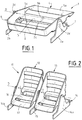
- the device 1 for assisting the movement of the feet which is shown in FIG. 1 is a simplified version in which the two feet will be animated together with the same movement.
- This device 1 comprises a frame 2 which must ensure the stability of the device when it rests on the work surface 3.
- This frame 2 must also serve as a support for the housing 4 for the feet of the user. More precisely, this housing 4 is mounted oscillating with respect to the frame 2, along a common axis of oscillation D.
- the frame 2 has a general U-shape, with two lateral branches 2 a and 2 b and a central branch 2 c .
- Each of the two lateral branches 2 a , 2 b has a step in height 2 d , which, in the example illustrated, has the shape of an isosceles triangle with the vertex which is opposite the work plane 3 .
- the housing 4 has a bottom 5, two lateral edges 6, 7 and a rear edge 8.
- the rear edge 8 keeps the user's foot at the heels in the housing 4.
- the two lateral flanges 6, 7 of the housing 4 are secured to the two lateral uprights 2 a , 2 b of the frame 2 by systems of rods and rivets not shown, which are mounted towards the upper end of the elevations 2 d of the uprights lateral 2 a , 2 b , aligned with each other, along the axis of oscillation D.
- the bottom 5 of the housing 4 is preferably made up of transverse plates, 5 a , 5 b , 5 c , from the front to the rear of the housing, in consideration of the position of the user. Said transverse plates are separated from each other. They are fixed at their two ends to the side edges 6, 7.
- Each transverse plate 5 a , 5 b , 5 c is moreover angularly offset with respect to the general direction of the bottom 5, so as to conform as perfectly as possible to the natural shape of the soles of the user's feet, when those these are in position in the housing 4.
- the frame 2 and the housing 4 are advantageously made by molding in a thermoplastic material.
- the operation of the foot movement aid device is as follows.
- the user is preferably seated, barefoot, or feet in socks. It has its two feet next to each other in the housing 4 so that its heels are applied to the rear edge 8.
- the implementation of the device is done at the discretion of the user, by simple tilting of the housing 4 relative to the axis of oscillation D. This tilting of the housing 4 and therefore of the feet of the user causes a movement of extension and retraction of the leg muscles which activates blood circulation.
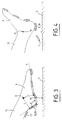
- FIG. 3 shows the position taken by the foot 9 during tilting of the housing 4 towards the front, that is to say during the movement of the foot corresponding to an extension.
- FIG. 4 shows the position taken by the foot 9 during the tilting of the housing 4 towards the rear, which corresponds to the retraction movement of the foot 9.
- the leg itself 10 retains the same position in the two movements of extension and retraction of the foot: only the foot 9 moves.
- the position of the axis of oscillation D has been determined relative to the housing 4 so that this axis of oscillation D is in the zone which corresponds substantially, for the two feet 9, to the axes of articulation of the foot c that is to say substantially at the level of the malleoli of the tibia and the fibula.
- This is a necessary condition so that the movement of the feet, which is achieved by means of the device 1 by the swinging around the axis of oscillation D, is as natural as possible, reproducing the movement of the ankles, without displacement of the legs. back and forth.
- the housing 4 must be at a sufficient height relative to the axis of oscillation D so that there is no contact between said housing 4 and the worktop 3 at any time.
- a device 1 has been produced which is suitable for a large majority of users, with the following configuration.
- the height H of the axis of oscillation D relative to the work plane is of the order of 110 mm.
- the distance L from the axis of oscillation D to the rear edge 8 is of the order of 85 mm.
- the distance l from the axis of oscillation D to the general direction of the bottom 5 is of the order of 60 mm.
- FIG. 2 shows a perspective view of an alternative embodiment of a device 11 for assisting the movement of the feet on which the movement of each foot is independent.
- This device 11 is particular compared to that which has just been described by the fact that it has two housings 12, 13, one for each leg, said housings being mounted oscillating with respect to the same axis of oscillation D.
- the frame 14, which has the same U-shaped configuration as the previous frame 2 has a middle branch 15, with a step in height, of triangular shape.
- the housings 12, 13 are secured to the frame 14 by rod / rivet systems, not shown, which are mounted at the upper ends of the notches in height of the lateral uprights 14 a , 14 b and of the median upright 15, as is clearly seen on the figure 2.
- the housings 12, 13 are adapted to the natural configuration of the base. Their bottom is also composed of three transverse plates which can have a slightly curved shape.
- the rear part of the housing includes not only the rear flange 16 on which the heel rests, but also a transverse plate, arranged more in height, forming a rear extension 17.
- the rim 16 is inclined relative to the general direction F of the bottom by an angle a which is of the order of 110 to 130 °.
- the rear extension 17 is also inclined in the same direction, with respect to the rear edge 16. This arrangement is understandable on examination of FIG. 3.
- the rear extension 17 makes it possible to support the foot during the extension movement.
- the position of the rear extension 17 is such that it does not cause contact with the work surface 3 during the retraction movement of the foot, as illustrated in FIG. 4.
- the user can carry out any movement of the feet simultaneously and with the same rocking as was the case of the device 1 with a single housing or alternatively simultaneous movements of the two feet or to movements involving only one foot at a time, the other being at rest.
- the invention is not limited to the embodiment which has just been described by way of example. It is also understood that the operation which has just been described while the user was in a seated position, can also extend to persons having a lying position. It suffices for this to secure the device so as to avoid any sliding, during use, on the work surface.
- the device can also be equipped with a protective coating, in particular in a textile material, making it possible to protect the feet of the user during use.
- a protective coating in particular in a textile material, making it possible to protect the feet of the user during use.
- this coating of use just fits on or around the housing so as to integrate with it. It surrounds the user's foot to form an envelope, protecting the foot in particular from the cold, like a slipper or a heater.
- the primary goal sought by the applicant is to propose a simplified device, allowing the user to spontaneously perform simple movements of the ankles, it is nevertheless possible to match the device of the invention with complementary means making it possible to assist the user in the practice of these movements.
- complementary means may for example consist of means for oscillating the rods mounted on the axis of oscillation of the device, so that the housing or the housings are driven in a rocking movement at a predetermined angle of oscillation. and according to a frequency also predetermined. Under these conditions, the device of the invention becomes a medical exerciser.
- Said additional means can, in another example, consist of means for braking the housings during their rocking, forcing the user to exert a certain pressure to carry out said movements.
Landscapes
- Health & Medical Sciences (AREA)
- Orthopedic Medicine & Surgery (AREA)
- General Health & Medical Sciences (AREA)
- Physical Education & Sports Medicine (AREA)
- Rehabilitation Tools (AREA)
- Percussion Or Vibration Massage (AREA)
Claims (11)
- Vorrichtung zur Bewegung der Füße, die ein Gestell (2) umfaßt, das geeignet ist, auf eine Arbeitsebene gestellt zu werden, und mindestens eine Aufnahme für die Füße, die so montiert ist, daß sie um eine Achse kippen kann, dadurch gekennzeichnet, daß die Kippachse (D) der Aufnahme (4) in einem Bereich angeordnet ist, der im wesentlichen der Drehachse der beiden Füße des Benutzers entspricht, wenn diese sich in der Aufnahme befinden, sowie dadurch, daß die Aufnahme (4) entlang dieser Kippachse (D) fest mit dem Gestell (2) verbunden ist, und zwar in einer solchen Höhe (H), daß beim Kippen der Aufnahme (4) um ihre Achse (D) kein Kontakt mit der Arbeitsebene (3) besteht.
- Vorrichtung nach Anspruch 1, dadurch gekennzeichnet, daß die Aufnahme aus einem Boden (5) für die Fußsohle, einer hinteren Stütze, die einen erhöhten Rand (8) für die Ferse bildet, und zwei seitlichen Stützen (6, 7) besteht, wobei jede Seitenstütze über eine Stange, welche eine Kippachse bildet, fest mit dem Gestell verbunden ist.
- Vorrichtung nach Anspruch 2, dadurch gekennzeichnet, daß der Boden (5) der Aufnahme (4) aus mehreren einzelnen Querplatten (5a, 5b, 5c) besteht, deren beiden Enden an den Seitenstützen (6, 7) befestigt sind, und die bezüglich der Gesamtrichtung (F) des Bodens (5) winklig versetzt sind und so geformt sind, daß sie der natürlichen Gesamtform der Fußsohle entsprechen.
- Vorrichtung nach Anspruch 2 oder 3, dadurch gekennzeichnet, daß der erhöhte Hinterrand (8) bezüglich der Gesamtrichtung (F) des Bodens um einen Winkel α der Größenordnung von 100 bis 130° geneigt ist.
- Vorrichtung nach Anspruch 1, dadurch gekennzeichnet, daß das Gestell, das den Sitz der Vorrichtung auf der Arbeitsebene gewährleistet, aus einem U-förmigen Rahmen (2) besteht, dessen Seitenleisten (2a, 2b) einen erhöhten Bereich (2d) zur Anordnung der Kippachse (D) aufweisen, und dessen Mittelleiste (2c) in Benutzungsposition gegenüber dem hinteren Teil der Aufnahme (4) angeordnet ist.
- Vorrichtung nach Anspruch 1, dadurch gekennzeichnet, daß sie zwei Aufnahmen (12, 13) aufweist, und zwar jeweils eine für jeden Fuß, wobei jede Aufnahme unabhängig von der anderen um die gleiche Kippachse (D) kippt.
- Vorrichtung nach den Ansprüchen 5 und 6, dadurch gekennzeichnet, daß das Gestell, das einen U-förmigen Rahmen (14) umfaßt, außerdem eine Zwischenleiste (15) umfaßt, die innerhalb des U in gleichem Abstand von den beiden Seitenleisten (14a, 14b) angeordnet ist, sowie dadurch, daß die Kippachse (D) einer gegebenen Aufnahme an dem erhöhten Bereich einerseits der Mittelleiste (15) und andererseits einer Seitenleiste (14a oder 14b) befestigt ist.
- Vorrichtung nach Anspruch 1, dadurch gekennzeichnet, daß die Höhe (H) der Kippachse (D) bezüglich der Arbeitsebene (3) etwa 110 mm, der Abstand (L) von der Kippachse (D) bis zum hinteren Rand (8) etwa 85 mm und der Abstand l von der Kippachse (D) zur Gesamtrichtung (F) des Bodens (5) etwa 60 mm beträgt.
- Vorrichtung nach Anspruch 1, dadurch gekennzeichnet, daß sie mindestens einen Schutzüberzug für die Füße aus einem Textilstoff umfaßt, der geeignet ist, sich der Aufnahme (4) anzupassen oder um diese herum anzuliegen.
- Vorrichtung nach Anspruch 1, dadurch gekennzeichnet, daß sie Kippantriebsvorrichtungen für die Kippachse (D) der Aufnahme bzw. der Aufnahmen aufweist.
- Vorrichtung nach Anspruch 1, dadurch gekennzeichnet, daß sie Bremsvorrichtungen für die Kippbewegung der Aufnahme bzw. der Aufnahmen aufweist.
Applications Claiming Priority (2)
| Application Number | Priority Date | Filing Date | Title |
|---|---|---|---|
| FR9400802A FR2715075B1 (fr) | 1994-01-20 | 1994-01-20 | Dispositif d'aide au mouvement des pieds. |
| FR9400802 | 1994-01-20 |
Publications (2)
| Publication Number | Publication Date |
|---|---|
| EP0664141A1 EP0664141A1 (de) | 1995-07-26 |
| EP0664141B1 true EP0664141B1 (de) | 1996-12-27 |
Family
ID=9459391
Family Applications (1)
| Application Number | Title | Priority Date | Filing Date |
|---|---|---|---|
| EP19950490001 Expired - Lifetime EP0664141B1 (de) | 1994-01-20 | 1995-01-10 | Hilfsgerät zur Bewegung der Füsse |
Country Status (4)
| Country | Link |
|---|---|
| EP (1) | EP0664141B1 (de) |
| CA (1) | CA2140318A1 (de) |
| DE (1) | DE69500115D1 (de) |
| FR (1) | FR2715075B1 (de) |
Families Citing this family (2)
| Publication number | Priority date | Publication date | Assignee | Title |
|---|---|---|---|---|
| CA2174714A1 (en) * | 1996-02-02 | 1997-08-03 | Charles Ho | Pivoting abdominal exercise apparatus |
| CN102406523B (zh) * | 2011-06-27 | 2013-06-05 | 徐金明 | 搁脚式足底热疗仪 |
Family Cites Families (4)
| Publication number | Priority date | Publication date | Assignee | Title |
|---|---|---|---|---|
| ES238952Y (es) * | 1978-10-06 | 1979-04-16 | Aparato gimnastico para activar la circulacion sanguinea. | |
| DE2941894A1 (de) * | 1979-10-17 | 1981-04-30 | C. & H. Leuthäußer Inh. Hilmar Leuthäußer, 8631 Wiesenfeld | Hoehenverstellbare fussstuetze |
| GB2084029B (en) * | 1980-09-26 | 1985-05-15 | Almansa Pastor A | Foot exercising apparatus |
| US5069446A (en) * | 1991-02-20 | 1991-12-03 | Larson Roger R | Physical rehabilitation device and method |
-
1994
- 1994-01-20 FR FR9400802A patent/FR2715075B1/fr not_active Expired - Fee Related
-
1995
- 1995-01-10 DE DE69500115T patent/DE69500115D1/de not_active Expired - Lifetime
- 1995-01-10 EP EP19950490001 patent/EP0664141B1/de not_active Expired - Lifetime
- 1995-01-16 CA CA 2140318 patent/CA2140318A1/en not_active Abandoned
Also Published As
| Publication number | Publication date |
|---|---|
| FR2715075B1 (fr) | 1996-04-05 |
| EP0664141A1 (de) | 1995-07-26 |
| FR2715075A1 (fr) | 1995-07-21 |
| CA2140318A1 (en) | 1995-07-21 |
| DE69500115D1 (de) | 1997-02-06 |
Similar Documents
| Publication | Publication Date | Title |
|---|---|---|
| JP2007503867A (ja) | 義足 | |
| EP0422167B1 (de) | Orthopädische vorrichtung für gehbehinderte | |
| EP0095396B1 (de) | Äussere Einrichtung zum aufrechten Stehen und Gehen von Personen mit motorischer Behinderung der unteren Gliedmassen | |
| FR2711915A3 (fr) | Dispositif pour masser la plante des pieds. | |
| EP1132015A1 (de) | Baueinheit aus Sohle und Keil | |
| CA2633898A1 (fr) | Chaussure therapeutique | |
| WO1997024041A1 (fr) | Orthese podiatrique a encoche de talon | |
| CA2894454A1 (fr) | Dispositif orthopedique pour un membre inferieur humain, chaussure et prothese equipees d'un tel dispositif | |
| BE1011626A3 (fr) | Prothese totale de genou a plateau tibial mobile en rotation. | |
| EP0664141B1 (de) | Hilfsgerät zur Bewegung der Füsse | |
| FR2559382A1 (fr) | Chaussure orthopedique reglable pour attelle de pieds | |
| JP2004344396A (ja) | 靴に取り付ける靴べら | |
| EP0025020B1 (de) | Orthopädischer Schuh mit sich automatisch aufrichtender Spitze beim Anheben des Fusses | |
| EP0514642A1 (de) | Langlauf-Skischuh | |
| EP1501383B1 (de) | Rollschuh | |
| FR2820970A1 (fr) | Orthese pour entorse externe de la cheville | |
| EP2464254A1 (de) | Massagevorrichtung | |
| FR3119971A1 (fr) | Système de stabilisation de chaussure notamment de sports pour obtenir une protection des chevilles au niveau des entorses ligamentaires par éversion ou inversion du pied. | |
| FR2832923A1 (fr) | Appareil formant orthese pour relever un pied dont les muscles sont atteints de paralysie ou de paresie | |
| EP0797937B1 (de) | Schuhsohle mit verformbarem Gewölbe und Schuh mit einer solchen Sohle | |
| EP0128115A1 (de) | Orthopädisches Gerät | |
| EP1841509A1 (de) | Gymnastikvorrichtung mit einer plattform | |
| FR2595566A1 (fr) | Dispositif pour soulager la colonne vertebrale particulierement pendant la marche ou la station debout | |
| FR2972103A1 (fr) | Plot sous talon ou plateau instable sous talon qui a pour but de desequilibrer la cheville dans un premier temps puis de rattraper cette instabilite grace au plateau superieur ou promontoire | |
| EP0329534A2 (de) | Auf Rädern gleitendes Sportgerät |
Legal Events
| Date | Code | Title | Description |
|---|---|---|---|
| PUAI | Public reference made under article 153(3) epc to a published international application that has entered the european phase |
Free format text: ORIGINAL CODE: 0009012 |
|
| AK | Designated contracting states |
Kind code of ref document: A1 Designated state(s): BE CH DE ES GB IT LI |
|
| 17P | Request for examination filed |
Effective date: 19960108 |
|
| GRAG | Despatch of communication of intention to grant |
Free format text: ORIGINAL CODE: EPIDOS AGRA |
|
| GRAH | Despatch of communication of intention to grant a patent |
Free format text: ORIGINAL CODE: EPIDOS IGRA |
|
| 17Q | First examination report despatched |
Effective date: 19960604 |
|
| GRAH | Despatch of communication of intention to grant a patent |
Free format text: ORIGINAL CODE: EPIDOS IGRA |
|
| GRAA | (expected) grant |
Free format text: ORIGINAL CODE: 0009210 |
|
| AK | Designated contracting states |
Kind code of ref document: B1 Designated state(s): BE CH DE ES GB IT LI |
|
| PG25 | Lapsed in a contracting state [announced via postgrant information from national office to epo] |
Ref country code: IT Free format text: LAPSE BECAUSE OF FAILURE TO SUBMIT A TRANSLATION OF THE DESCRIPTION OR TO PAY THE FEE WITHIN THE PRESCRIBED TIME-LIMIT;WARNING: LAPSES OF ITALIAN PATENTS WITH EFFECTIVE DATE BEFORE 2007 MAY HAVE OCCURRED AT ANY TIME BEFORE 2007. THE CORRECT EFFECTIVE DATE MAY BE DIFFERENT FROM THE ONE RECORDED. Effective date: 19961227 Ref country code: ES Free format text: THE PATENT HAS BEEN ANNULLED BY A DECISION OF A NATIONAL AUTHORITY Effective date: 19961227 |
|
| REF | Corresponds to: |
Ref document number: 69500115 Country of ref document: DE Date of ref document: 19970206 |
|
| PG25 | Lapsed in a contracting state [announced via postgrant information from national office to epo] |
Ref country code: DE Effective date: 19970328 |
|
| PGFP | Annual fee paid to national office [announced via postgrant information from national office to epo] |
Ref country code: CH Payment date: 19970402 Year of fee payment: 3 |
|
| PGFP | Annual fee paid to national office [announced via postgrant information from national office to epo] |
Ref country code: BE Payment date: 19970403 Year of fee payment: 3 |
|
| GBT | Gb: translation of ep patent filed (gb section 77(6)(a)/1977) |
Effective date: 19970407 |
|
| PLBE | No opposition filed within time limit |
Free format text: ORIGINAL CODE: 0009261 |
|
| STAA | Information on the status of an ep patent application or granted ep patent |
Free format text: STATUS: NO OPPOSITION FILED WITHIN TIME LIMIT |
|
| 26N | No opposition filed | ||
| PG25 | Lapsed in a contracting state [announced via postgrant information from national office to epo] |
Ref country code: BE Free format text: LAPSE BECAUSE OF NON-PAYMENT OF DUE FEES Effective date: 19980131 |
|
| BERE | Be: lapsed |
Owner name: WRIGHTON RICHARD Effective date: 19980131 |
|
| PG25 | Lapsed in a contracting state [announced via postgrant information from national office to epo] |
Ref country code: GB Free format text: LAPSE BECAUSE OF NON-PAYMENT OF DUE FEES Effective date: 19990110 |
|
| PG25 | Lapsed in a contracting state [announced via postgrant information from national office to epo] |
Ref country code: LI Free format text: LAPSE BECAUSE OF NON-PAYMENT OF DUE FEES Effective date: 19990131 Ref country code: CH Free format text: LAPSE BECAUSE OF NON-PAYMENT OF DUE FEES Effective date: 19990131 |
|
| GBPC | Gb: european patent ceased through non-payment of renewal fee |
Effective date: 19990110 |
|
| REG | Reference to a national code |
Ref country code: CH Ref legal event code: PL |