EP0664011B1 - Vibrierendes bohrgerät für seismische exploration - Google Patents
Vibrierendes bohrgerät für seismische exploration Download PDFInfo
- Publication number
- EP0664011B1 EP0664011B1 EP93923303A EP93923303A EP0664011B1 EP 0664011 B1 EP0664011 B1 EP 0664011B1 EP 93923303 A EP93923303 A EP 93923303A EP 93923303 A EP93923303 A EP 93923303A EP 0664011 B1 EP0664011 B1 EP 0664011B1
- Authority
- EP
- European Patent Office
- Prior art keywords
- pinion gear
- elongated member
- force
- rack gear
- elongated
- Prior art date
- Legal status (The legal status is an assumption and is not a legal conclusion. Google has not performed a legal analysis and makes no representation as to the accuracy of the status listed.)
- Expired - Lifetime
Links
Images



Classifications
-
- E—FIXED CONSTRUCTIONS
- E21—EARTH OR ROCK DRILLING; MINING
- E21B—EARTH OR ROCK DRILLING; OBTAINING OIL, GAS, WATER, SOLUBLE OR MELTABLE MATERIALS OR A SLURRY OF MINERALS FROM WELLS
- E21B7/00—Special methods or apparatus for drilling
- E21B7/24—Drilling using vibrating or oscillating means, e.g. out-of-balance masses
Definitions
- the present invention generally relates to seismic exploration and more particularly to a vibrating hole forming device in which a vertically elongated mounting pipe with attached rack gear is powered vertically by a hydraulically driven pinion gear which will mechanically push the pipe downwardly into the earth's surface.
- a vibrating mechanism imparts vibration to the downward force exerted by the pinion gear and rack gear. Vibration is imparted to the pipe automatically when hydraulic pressure required to operate the pinion gear reaches a predetermined pressure such as when the point on the lower end of the pipe encounters a predetermined resistance to further downward movement.
- This enables a lightweight unit to impart a constant downward force and a vibration force when needed to enable the device to penetrate through sands or extremely dense subsurface terrain thereby eliminating the necessity of providing a heavy weight vehicle such as is required when conventional hole forming devices are employed.
- seismic exploration of underground formations is conducted by positioning a plurality of explosive seismic charges below ground level at a designated depth and in a designated pattern with these charges being subsequently detonated to produce seismograph recordings which can be analyzed to determine the character of the underground formation including whether the underground strata includes potentially recoverable oil or gas deposits and the like.
- Various devices have been provided to form vertical bores or holes in the earth's surface in which seismic charges are placed. Seismic exploration is necessarily conducted in locations having difficult access and terrain characteristics which are difficult to traverse.
- Various types of vehicles are utilized to convey seismic exploration equipment to an exploration site. Such vehicles are necessarily relatively heavy in order to provide a downward force on drilling or other earth penetrating equipment used to form vertical holes or bores in the earth to receive the explosive seismic charges. The necessity of making such vehicles heavy also introduces additional problems of gaining access to an exploration site.
- the following U.S. patents relate to this field of endeavor and include vibrating devices to assist in forming bore holes.
- An object of the present invention is to provide a device capable of forming a vertical hole or bore for inserting a seismic charge below ground level to a designated depth to facilitate production of seismograph recordings which includes an elongated vertically disposed pipe that is supported and guided for vertical reciprocation with the pipe having an elongated rack gear mounted thereon in meshing engagement with a hydraulically driven pinion gear by which the pipe with a point on the lower end can be pushed downwardly into the earth to a predetermined desired depth.
- Another object of the invention is to provide a vibrating hole forming device in accordance with the preceding object in which a vibrating mechanism including a framework with a vibrator mounted thereon is operatively connected with the pinion gear to automatically vibrate the rack gear, pipe and point on the lower end vertically when a predetermined resistance to earth penetration is encountered by the point on the lower end of the pipe thus utilizing a downward force and a vibrating force in the form of an up and down motion when the resistance found in subsurface formations is greater than the weight and force capabilities of the device with this combination of downward force and vibration force delivering a dual force which can be produced by a lightweight unit which will penetrate through sands or extremely dense subsurface terrain with relative ease thereby eliminating the necessity of an excessive weight factor being incorporated into the vehicle or vessel on which the device is mounted.
- Still another object of the invention is to provide a vibrating hole forming device for seismic exploration as set forth in the preceding objects in which the supporting and guide structure as well as the operating structures cooperate to efficiently position a plurality of explosive seismic charges in a desired pattern and at a desired depth with the device being relatively inexpensive to construct, longlasting and dependable, efficient and capable of being mounted on lightweight vehicles or vessels to facilitate transport to an exploration site as compared with a relatively heavy vehicle which would be necessary to provide a reaction force if the vibrating mechanism of the present invention was not used.
- Figure 1 is a perspective view of the vibrating hole forming device for seismic exploration illustrating the overall structural details of the invention.
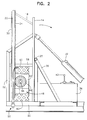
- Figure 2 is a fragmental vertical sectional view, on an enlarged scale, of the operative components of the device of the present invention.
- Figure 3 is a detailed vertical sectional view, on an enlarged scale, illustrating structural details of the hydraulic drive mechanism exerting downward force on the vertically movable pipe.
- Figure 4 is a transverse, plan sectional view taken along section line 4-4 on Fig. 3 illustrating further structural details of the hydraulic drive.
- Figure 5 is a schematic flow diagram illustrating the hydraulic drive mechanism and the structure which automatically actuates the vibrating mechanism when a predetermined resistance to penetration of an underground formation by the point on the mounting pipe is encountered.
- Figure 6 is a plan view of the vibratory exciter used in this invention.
- Figure 7 is a vertical sectional view of the vibratory exciter taken generally along section line 7-7 on Fig. 6.
- the vibrating hole forming device incorporating the present invention therein is generally designated by reference numeral 10 and includes a vertical tower or framework 12 which tapers upwardly and includes vertical members 14, horizontal brace members 16 and diagonal brace members 18.
- the structure and configuration of the tower can vary but usually it is of triangular cross-sectional configuration with one of the vertical members 18 being in the form of an elongated rigid generally semicylindrical guide tube or sleeve 20 which guidingly supports an elongated mounting pipe 22 therein with the mounting pipe 22 mounting and supporting an elongated, continuous rack gear 24 which extends substantially throughout the length of the mounting pipe 22 and faces away from guide tube 20.
- the tower 12 is preferably mounted on a supporting frame or skid 26 which may be positioned on a vessel or may be incorporated into various types of land vehicles.
- the lower end of the tower may be pivotally supported by a horizontally disposed, transversely extending pivot arrangement 28 supported by bracing 30 connected to the frame 26 with hydraulic piston and cylinder assemblies 32 pivoting the tower 18 and related structure to a horizontal position while the device 10 is being transported to a use site and to a vertical position when set up for use.
- Supported on the frame is a hydraulic pump unit 34, prime mover or motor 36 for driving the same combined with a tank 38 to store and supply hydraulic fluid and a control valve assembly 42 by which the device may be operated.
- the control valve assembly 42 includes a control for pivoting the tower 12 between horizontal and vertical positions and provides pressurized hydraulic fluid to a hydraulic motor 44 which drives a pinion gear 46 in meshing engagement with the rack gear 24.
- the control valve assembly 42 also supplies hydraulic fluid to a hydraulically driven vibratory exciter 48 which operates to impart vertical vibratory movement and forces to the mounting pipe 22 through the pinion gear 46 and rack gear 24.
- the mounting pipe 22 includes a disposable point generally designated by reference numeral 50 on the lower end thereof.
- the lower end of the tower 12 includes a vertically disposed supporting frame 52 which includes a bracket structure 54 supporting the lower end of the guide tube 20 with the bracket structure 54 being adjustable to compensate for wear between the guide tube 20 and the pipe 22.
- a bottom frame member 56 and a top frame member 58 of the frame 52 Positioned between a bottom frame member 56 and a top frame member 58 of the frame 52 is a pair of rubber latticework supports 60 which supports a housing structure 62 supporting the pinion gear 46 and hydraulic motor assembly 44 and the vibratory exciter 48 as illustrated in Figs. 2 and 3.
- the vibratory exciter 48 includes a housing 64 with a pair of rotating eccentrically weighted members 66 therein which may be similar to the structure disclosed in U.S. Patent No. 4,819,740 issued April 11, 1989 or U.S. Patent No.
- the housing 64 of the vibratory exciter is rigidly affixed to the housing 62 for rack gear 46 such as by welding or the like and both of these units are supported by the lattice rubber machinery mounts or supports 60 from the frame members 56 and 58.
- Four machinery mounts or supports 60 are provided as illustrated in Fig. 1 to reduce the amount of vibration transferred to the frame 52 and isolate the vibration to the area and equipment between the rubber lattice machine mounts or supports 60.
- the frequency and amplitude of the vibratory exciter may be varied such as by varying the amount of weight in the form of lobes on each eccentric rotable weight 66 in the vibratory exciter and the frequency can be varied by also varying the eccentric weight orientation on the eccentric weights 66 rather than by using a variable speed motor.
- the vibratory exciter is driven by a hydraulic motor with suitable controls 68 similar to the hydraulic motor 44 for driving the pinion gear 46 that is supported by a shaft 96 supported by bearings 98 in the housing 62 with the motor being provided with a bracket 102 all of which cooperate to impart rotation to the pinion gear 46 to move the pipe 22 vertically with the vibratory exciter being actuated automatically by the vibratory hydraulic motor 110, illustrated schematically in Fig. 5, which is energized when downward resistance encountered by the point 50 and pipe 22 exceeds a predetermined resistance.
- the pump 34 and motor 36 are schematically illustrated with the pump 34 being communicated with the tank schematically illustrated at 38.
- the pump discharges pressurized fluid through a relief valve 112 to manual control valve assemblies 42 for actuating the motor 44 for the pinion gear 46 and the lay down piston and cylinder assemblies 32 for the tower with pressure line 114 interconnecting the relief valve 112 and the control valve assemblies 42 and a drain line 116 returning fluid back to the tank 38.
- the pump 34 also supplies pressurized fluid to a relief valve 118 supplying pressurized fluid through pressure line 120 to a pressure reducing relief valve 122 and a check valve 124 with the relief valves 118 and 122 including drain lines 126 back to the tank 38.
- the valve 122 includes a pilot line 128 communicated with pressure line 114 which conveys the pressure in line 114 into valve 122 for control thereof.
- pressure line 114 When the motor 44 encounters a predetermined resistance to rotation due to the point 50 encountering resistance to penetration of the subsurface formation of a certain magnitude, the pressure in line 114 will increase and cause valve 122 to supply fluid past the check valve to the hydraulic motor 110 for the vibratory exciter 48 with the motor 110 including a drain line 130 back to the tank 38.
- the vibratory exciter motor will not be energized.
- the pilot line 128 will actuate the valve 122 to supply pressurized fluid to the vibratory motor 110 thus introducing a vibrating movement and force to the mounting pipe 22 and point 50 in order to enable the resistance to penetration to be overcome by using the dual force that is exerted by the drive pinion and weight of the unit and the vehicle on which it is mounted and the vibrating force which is automatically actuated when the resistance to penetration reaches a predetermined resistance.
- the check valve 124 and the pressure relief valve 122 provide a bypass of the fluid through the valve 122 back into the drain line 126.
- pressure in the pilot line 128 increases, the valve 122 will then cause pressurized fluid to overcome the check valve 124 and communicate pressure line 120 with the hydraulic motor 110 for the vibratory exciter 48.
- the location of the vibratory exciter 48 may vary as long as equal vibratory forces are exerted symmetrically on the housing 62 to move the shaft 96 and pinion gear 46 vertically while maintaining meshing contact between the pinion gear 46 and the rack gear 24.
- the hydraulic motor driving the shaft 96 for the pinion gear 46 may be provided with a suitable reduction gear to move the mounting or planting pipe 22 at a desired relatively slow speed.
- the downward force that could normally be applied to the pipe 22 would be the weight of the unit and vehicle to which it is attached and any downward force which exceeded this weight would lift the unit and vehicle.
- a relatively heavy vehicle would be required in order to provide adequate downward force to the structure which formed the hole in the earth.
- a dual force is exerted including the vibration movement which enables a downward force to be obtained which is greater than the weight of the unit and vehicle.
- the forces produced by the vibratory exciter 48 cause the housing 62 to vibrate vertically and this force is transferred to the pinion gear 46 and shaft which are supported from the housing 62 thereby transferring impulses from the vibratory exciter 48 to the pinion gear 46 which then transmits the same to the rack gear 24 welded to the pipe 22 thereby producing a downward force by a lightweight unit that has extraordinary penetrating capabilities.
- the vibratory exciter 48 is automatically actuated when the point on the pipe comes into contact with a dense subsurface formation and encounters a resistance that cannot be penetrated by the downward force provided by the weight of the unit and vehicle.
- the addition of the vibratory exciter and the forces produced thereby will enable penetration without requiring a heavy unit or vehicle with the vibration forces automatically ceasing when the dense subsurface formation has been penetrated.
- the vibratory force generated by the present invention is only used when downward force produced by the unit is overcome or exceeded by the resistance encountered in dense subsurface formations.
Landscapes
- Geology (AREA)
- Life Sciences & Earth Sciences (AREA)
- Engineering & Computer Science (AREA)
- Mining & Mineral Resources (AREA)
- Environmental & Geological Engineering (AREA)
- Fluid Mechanics (AREA)
- Physics & Mathematics (AREA)
- General Life Sciences & Earth Sciences (AREA)
- Geochemistry & Mineralogy (AREA)
- Geophysics And Detection Of Objects (AREA)
- Placing Or Removing Of Piles Or Sheet Piles, Or Accessories Thereof (AREA)
- Earth Drilling (AREA)
- Investigation Of Foundation Soil And Reinforcement Of Foundation Soil By Compacting Or Drainage (AREA)
Claims (15)
- Vibrierende, ein Bohrloch bildende Vorrichtung zur seismischen Bodenforschung, mit der ein Loch abwärts gerichtet in der Oberfläche der Erde zur Plazierung einer explosiven seismischen Ladung am Boden dieses Lochs gebildet werden kann, wobei die Vorrichtung folgendes umfaßt: ein Gestell, eine verlängerte, vertikal ausgerichtete Führung, die auf dem Gestell gehalten wird, ein längliches, vertikal angebrachtes Rohrelement, das von der Führung derart gehalten und geführt wird, daß es sich hin- und herbewegen kann, und das an dem unteren Ende davon eine Spitze aufweist, wobei das Rohrelement einen sich in Längsrichtung erstreckenden, kontinuierlichen Zahnstangentrieb umfaßt, der starr damit verbunden ist, ein drehbar auf dem Gestell gehaltenes Ritzel, das in Zahneingriff mit dem Zahnstangentrieb steht, um den Zahnstangentrieb und das Rohrelement vertikal zu bewegen, einen Antriebsmotor, der mit dem Ritzel verbunden ist, um das Ritzel zur Aufwärts- und Abwärtsbewegung des Rohrelements und des Zahnstangentriebs selektiv anzutreiben, und Mittel zum Beaufschlagen des Rohrelements mit Vibrationskräften, wobei das Mittel, das das Rohrelement mit Vibrationskräften beaufschlagt, das Ritzel und den Antriebsmotor umfaßt, die auf einem Rahmentragwerk angeordnet sind, Mittel zum Anbringen des Rahmentragwerks an dem Gestell derart, daß dieses eine federnde, vertikal geführte Bewegung durchführen kann, und Vibrationen erzeugende Mittel, die auf dem Rahmentragwerk angebracht sind, um das Rahmentragwerk und das Ritzel vertikal hin- und herzubewegen, um so auf den Zahnstangentrieb, das Rohrelement und die Spitze an dem unteren Ende des Rohrelements eine vertikale Vibration zu übertragen, damit dichte Erdschichfformationen durchdrungen werden können, die der Durchdringung Widerstand leisten, indem eine konstante, nach unten gerichtete Kraft auf das Rohrelement ausgeübt wird, während das Rohrelement vertikal mit einer Vibration beaufschlagt wird, wobei das Vibrationserzeugungsmittel einen Vibrationserreger, der durch hydraulischen Druck angetrieben wird, und Mittel umfaßt, die automatisch den Betrieb des Vibrationserregers starten, wenn der Durchdringungswiderstand an der Spitze an dem unteren Ende des Rohrelements einen Widerstand gegenüber der Durchdringung einer Erdschichtformation erzeugt, der größer als das Gewicht der Vorrichtung und eines zugehörigen Fahrzeugs ist, wodurch ermöglicht wird, daß ein Bohrloch durch die Verwendung von leichtgebauten Fahrzeugen und leichtgebauter Ausrüstung gebildet wird, die in der Lage sind, unebenes Terrain mit einer größeren Effizienz zu durchqueren als schwere Fahrzeuge.
- Vorrichtung nach Anspruch 1, bei der das Rahmentragwerk und das Gestell zusammenwirkende Führungsmittel und elastische Mittel umfassen, die eine vertikale Vibration des Rahmenwerks und des Rohrelements ermöglichen.
- Verfahren zur Bildung eines Bohrlochs in der Oberfläche der Erde, das aus den folgenden Schritten besteht: Positionieren eines vertikalen länglichen Elements an einer Stelle, an der ein Bohrloch gewünscht wird, Anlegen einer im wesentlichen konstanten, nach unten gerichteten Kraft an dem Element, um dieses nach unten in die Erde zu bewegen, wenn man auf den erwarteten Widerstand gegenüber der nach unten gerichteten Bewegung desselben trifft, und Beaufschlagen des Elements mit einer vertikalen Vibrationskraft nur dann, wenn das Element auf einen vorbestimmten, größer als erwarteten Widerstand gegenüber der nach unten gerichteten Bewegung in die Erde trifft, wodurch sowohl die im wesentlichen konstante, nach unten gerichtete Kraft als auch die vertikale Vibrationskraft kombiniert dazu verwendet werden, das Element durch den angetroffenen, größer als erwarteten, vorbestimmten Widerstand nach unten zu bewegen.
- Verfahren nach Anspruch 3, zusammen mit den Schritten des lösbaren Befestigens eines spitzen unteren Endes an dem vertikalen Element und Abtrennen des spitzen unteren Endes von dem länglichen Element, wenn das längliche Element zurückgezogen wird, wodurch das spitze untere Ende in dem Boden eines in der Erde gebildeten Lochs zurückgelassen wird.
- Verfahren nach Anspruch 4, zusammen mit dem Schritt des Anbringens einer explosiven Ladung an dem spitzen unteren Ende, das auf dem Boden des gebildeten Bohrlochs bleiben soll, um zur Verwendung bei der seismischen Untersuchung zu detonieren.
- Verfahren nach Anspruch 5, zusammen mit dem Schritt des Verankerns des spitzen unteren Endes an dem Boden des gebildeten Lochs, wenn das längliche Element zurückgezogen wird.
- Verfahren nach Anspruch 3, bei dem der Schritt des Anlegens der konstanten nach unten gerichteten Kraft an das längliche Element die Verwendung eines Hydraulikmotors einschließt, der ein Ritzel antreibt, das mit einem länglichen Zahnstangentrieb kämmt, der auf dem länglichen Element angebracht ist.
- Verfahren nach Anspruch 7, bei dem der Schritt des Anlegens der vertikalen Vibrationskraft an das längliche Element den Schritt des Anlegens einer vertikalen Vibrationskraft an das Ritzel umfaßt, wobei das Ritzel die vertikale Vibrationskraft auch auf den Zahnstangentrieb und das längliche Element überträgt.
- Verfahren nach Anspruch 8, bei dem der Schritt des Anlegens der vertikalen Vibrationskraft den Schritt des Antreibens einer Vibrationsvorrichtung durch einen Hydraulikmotor umfaßt, der mit einer Hochdruckfluidquelle in Verbindung gebracht wird in Reaktion auf einen Druckaufbau in einer Druckzufuhfleitung, die mit dem Hydraulikmotor in Verbindung steht, der das Ritzel antreibt.
- Vibrierende, ein Bohrloch bildende Vorrichtung mit einen Gestell, das eine längliche Führung trägt, einem länglichen, starren, loch bildenden Element, das von der Führung so gehalten und geführt wird, daß es sich hin- und herbewegen kann, wobei das längliche Element einen sich in Längsrichtung erstreckenden, kontinuierlichen Zahnstangentrieb besitzt, der starr damit verbunden ist, einem Ritzel, das drehbar von dem Gestell gehalten wird und mit dem Zahnstangentrieb in Zahneingriff steht, um den Zahnstangentrieb und das längliche Element in der Längsrichtung zu bewegen, Mittel, die mit dem Ritzel verbunden sind, um das Ritzel selektiv anzutreiben, um das längliche Element und den Zahnstangentrieb in der Längsrichtung zu bewegen, und Mittel, die das längliche Element nur dann in einer Längsrichtung durch das kämmende Ritzel und den Zahnstangentrieb mit Vibrationskräften beaufschlagen, wenn das längliche Element auf einen vorbestimmten, unerwarteten Widerstand bei der Bildung eines Bohrlochs trifft.
- Vorrichtung nach Anspruch 10, bei der das Mittel, das das Ritzel antreibt, einen Hydraulikmotors umfaßt, um das längliche Element mit einer im allgemeinen konstanten Geschwindigkeit und Kraft zu bewegen.
- Vorrichtung nach Anspruch 11, bei der das Ritzel und der Motor auf einem Träger angebracht sind, der an dem Gestell so befestigt ist, daß eine federnde geführte Bewegung in der gleichen Richtung durchgeführt werden kann, in der sich das längliche Element bewegt, wobei das Vibrationskräfte anlegende Mittel Vibrationserzeugungsmittel umfaßt, die auf dem Träger montiert sind, um diesen hin- und herzubewegen, damit auf das Ritzel, den Zahnstangentrieb und das längliche Element eine Vibration übertragen wird, wobei das längliche Element eine Spitze an dem Ende davon aufweist, um Bereiche zu durchdringen, die sich der Durchdringung widersetzen, indem eine konstante Kraft auf das längliche Element ausgeübt wird, während dieses mit einer Vibration beaufschlagt wird.
- Vorrichtung zur Bildung eines Bohrlochs nach Anspruch 10, bei der das Ritzel und das Mittel zum Antreiben des Ritzels auf einem Rahmentragwerk montiert sind, und mit Mitteln, die das Rahmentragwerk ausgehend von dem Gestell elastisch halten, um eine begrenzte federnde Bewegung des Rahmentragwerks in der Längsrichtung der Bewegung des länglichen Elements zu erlauben, um so die Vibrationskräfte gegenüber dem Gestell zu isolieren.
- Vorrichtung zur Bildung eines Bohrlochs nach Anspruch 13, bei der das Mittel zum Tragen des Rahmentragwerks ausgehend von dem Gestell einen Block aus gitterförmigem elastischem Material umfaßt, der stützend mit gegenüberliegenden Bereichen des Rahmentragwerks in Eingriff kommt, wobei das Gestell beabstandete Stützbereiche umfaßt, die sich in stützendem Eingriff mit den Blöcken in entgegengesetzter Beziehung zu dem Rahmentragwerk befinden.
- Element zur Bildung eines Bohrlochs nach Anspruch 10, bei dem das die Vibrationskräfte an legende Mittel einen Motor, der das Ritzel antreibt, und eine motorbetriebene Vibrationsvorrichtung, die mit einer Stütze für das Ritzel verbunden ist, und Mittel umfaßt, die die Kraft erfassen, die von dem Motor ausgeübt wird, wenn das Ritzel angetrieben wird, und die die Vibrationsvorrichtung aktivieren, wenn die von diesem Motor ausgeübte Kraft eine Kraft übersteigt, die notwendig ist, um das längliche Element in einer Längsrichtung zu bewegen, wenn das längliche Element auf einen erwarteten Widerstand trifft.
Applications Claiming Priority (3)
| Application Number | Priority Date | Filing Date | Title |
|---|---|---|---|
| US961851 | 1992-10-16 | ||
| US07/961,851 US5281775A (en) | 1992-10-16 | 1992-10-16 | Vibrating hole forming device for seismic exploration |
| PCT/US1993/009588 WO1994009386A1 (en) | 1992-10-16 | 1993-10-13 | Vibrating hole forming device for seismic exploration |
Publications (3)
| Publication Number | Publication Date |
|---|---|
| EP0664011A1 EP0664011A1 (de) | 1995-07-26 |
| EP0664011A4 EP0664011A4 (de) | 1997-12-29 |
| EP0664011B1 true EP0664011B1 (de) | 1999-03-10 |
Family
ID=25505103
Family Applications (1)
| Application Number | Title | Priority Date | Filing Date |
|---|---|---|---|
| EP93923303A Expired - Lifetime EP0664011B1 (de) | 1992-10-16 | 1993-10-13 | Vibrierendes bohrgerät für seismische exploration |
Country Status (10)
| Country | Link |
|---|---|
| US (1) | US5281775A (de) |
| EP (1) | EP0664011B1 (de) |
| AT (1) | ATE177538T1 (de) |
| AU (1) | AU679699B2 (de) |
| BR (1) | BR9307253A (de) |
| CA (1) | CA2147891C (de) |
| DE (1) | DE69323888T2 (de) |
| NZ (1) | NZ257030A (de) |
| OA (1) | OA09973A (de) |
| WO (1) | WO1994009386A1 (de) |
Families Citing this family (37)
| Publication number | Priority date | Publication date | Assignee | Title |
|---|---|---|---|---|
| US5488999A (en) * | 1994-04-19 | 1996-02-06 | Serrette; Billy J. | Drill bit for geological exploration |
| DE4425905A1 (de) * | 1994-07-21 | 1996-01-25 | Bald Hubert | Vorrichtung und Verfahren zur Kompensation von Querschwingungen an Unwuchtvibratoren mit vorgegebener Schwingrichtung |
| US5540295A (en) * | 1995-03-27 | 1996-07-30 | Serrette; Billy J. | Vibrator for drill stems |
| DE19528620A1 (de) * | 1995-08-04 | 1997-02-06 | Tracto Technik | Erdbohrgerät |
| DE19543910A1 (de) * | 1995-11-26 | 1997-05-28 | Gedib Ingbuero Innovation | Verstelleinrichtung für einen Unwucht-Richtschwinger mit verstellbarem Fliehmoment |
| US5658091A (en) * | 1996-01-29 | 1997-08-19 | Geotechnics America, Inc. | Apparatus for inserting prefabricated vertical drains into the earth |
| US5860482A (en) * | 1996-01-30 | 1999-01-19 | Ernie J. Gremillion | Multiple force hole forming device |
| US5811741A (en) * | 1997-03-19 | 1998-09-22 | Coast Machinery, Inc. | Apparatus for placing geophones beneath the surface of the earth |
| US6234260B1 (en) * | 1997-03-19 | 2001-05-22 | Coast Machinery, Inc. | Mobile drilling apparatus |
| US6543966B2 (en) | 1997-07-25 | 2003-04-08 | American Piledriving Equipment, Inc. | Drive system for inserting and extracting elongate members into the earth |
| US6431795B2 (en) | 1997-07-25 | 2002-08-13 | American Piledriving Equipment, Inc. | Systems and methods for inserting wick drain material |
| US6039508A (en) * | 1997-07-25 | 2000-03-21 | American Piledriving Equipment, Inc. | Apparatus for inserting elongate members into the earth |
| US6447036B1 (en) | 1999-03-23 | 2002-09-10 | American Piledriving Equipment, Inc. | Pile clamp systems and methods |
| US6419044B1 (en) | 1999-04-20 | 2002-07-16 | Schlumberger Technology Corporation | Energy source for use in seismic acquisitions |
| GB0001323D0 (en) * | 2000-01-20 | 2000-03-08 | Sol Comp Du | Rotary displacement piling equipment |
| NO20011425L (no) | 2000-03-24 | 2001-09-25 | Westerngeco Seismic Holdings | Seismic Shot-Hole Drill System |
| US6540034B1 (en) | 2000-04-29 | 2003-04-01 | Westerngeco L.L.C. | Portable seismic shothole drilling system |
| US7694747B1 (en) | 2002-09-17 | 2010-04-13 | American Piledriving Equipment, Inc. | Preloaded drop hammer for driving piles |
| WO2005087393A1 (en) * | 2004-03-18 | 2005-09-22 | Flexidrill Limited | Vibrational heads and assemblies and uses thereof |
| US7392855B1 (en) * | 2005-04-27 | 2008-07-01 | American Piledriving Equipment, Inc. | Vibratory pile driving systems and methods |
| US7854571B1 (en) | 2005-07-20 | 2010-12-21 | American Piledriving Equipment, Inc. | Systems and methods for handling piles |
| NZ542700A (en) * | 2005-09-27 | 2008-05-30 | Flexidrill Ltd | Drill string suspension with vibrational head floatably connected to a support |
| NZ554256A (en) * | 2007-03-29 | 2009-11-27 | Flexidrill Ltd | Drive vibrational drilling |
| ATE457411T1 (de) * | 2007-09-19 | 2010-02-15 | Bauer Maschinen Gmbh | Bohrgerät und verfahren zum betreib eines bohrgeräts |
| US8763719B2 (en) | 2010-01-06 | 2014-07-01 | American Piledriving Equipment, Inc. | Pile driving systems and methods employing preloaded drop hammer |
| US8434969B2 (en) | 2010-04-02 | 2013-05-07 | American Piledriving Equipment, Inc. | Internal pipe clamp |
| CN102819041B (zh) * | 2012-08-28 | 2014-12-10 | 中国石油化工股份有限公司 | 一种利用土层阻力信息确定地震炸药激发深度的方法 |
| US9249551B1 (en) | 2012-11-30 | 2016-02-02 | American Piledriving Equipment, Inc. | Concrete sheet pile clamp assemblies and methods and pile driving systems for concrete sheet piles |
| US9371624B2 (en) | 2013-07-05 | 2016-06-21 | American Piledriving Equipment, Inc. | Accessory connection systems and methods for use with helical piledriving systems |
| US10392871B2 (en) | 2015-11-18 | 2019-08-27 | American Piledriving Equipment, Inc. | Earth boring systems and methods with integral debris removal |
| US9957684B2 (en) | 2015-12-11 | 2018-05-01 | American Piledriving Equipment, Inc. | Systems and methods for installing pile structures in permafrost |
| US10273646B2 (en) | 2015-12-14 | 2019-04-30 | American Piledriving Equipment, Inc. | Guide systems and methods for diesel hammers |
| US10538892B2 (en) | 2016-06-30 | 2020-01-21 | American Piledriving Equipment, Inc. | Hydraulic impact hammer systems and methods |
| US12129623B2 (en) | 2021-03-31 | 2024-10-29 | American Piledriving Equipment, Inc. | Segmented ram systems and methods for hydraulic impact hammers |
| CN114151010B (zh) * | 2021-12-14 | 2023-12-08 | 刘继芳 | 一种矿产地质勘查装置 |
| US12461260B2 (en) * | 2022-03-01 | 2025-11-04 | Arizona Board Of Regents On Behalf Of The University Of Arizona | Seismic source |
| US12606972B2 (en) | 2024-02-07 | 2026-04-21 | American Piledriving Equipment, Inc. | Variable moment vibratory systems and methods |
Family Cites Families (9)
| Publication number | Priority date | Publication date | Assignee | Title |
|---|---|---|---|---|
| GB872923A (en) * | 1959-04-25 | 1961-07-12 | Mueller Ludwig | Improvements relating to devices for ramming or driving piles or other elements |
| US3242999A (en) * | 1963-08-07 | 1966-03-29 | Chevron Res | Method and apparatus for positioning geophones in subterranean earth formations |
| US3394766A (en) * | 1966-03-11 | 1968-07-30 | Lebelle Jean Louis | Apparatus for emplacing elongated rigid members into the soil selectively in a vibratory mode or in a percussive mode |
| US3752242A (en) * | 1971-11-16 | 1973-08-14 | E Gremillion | Hydraulically actuated cavity forming device |
| US3920083A (en) * | 1974-05-03 | 1975-11-18 | Toyoda Kikai Kogyo Kk | Pile driving and drawing apparatus |
| US3939771A (en) * | 1974-06-03 | 1976-02-24 | Mcreynolds Oliver B | Seismic explosive charge loader and anchor |
| US4471669A (en) * | 1982-01-21 | 1984-09-18 | J. I. Case Company | Track drive system with dual mode steering |
| US4553443A (en) * | 1982-11-19 | 1985-11-19 | Geomarex | High frequency vibratory systems for earth boring |
| US4819740A (en) * | 1987-11-16 | 1989-04-11 | Vulcan Iron Works Inc. | Vibratory hammer/extractor |
-
1992
- 1992-10-16 US US07/961,851 patent/US5281775A/en not_active Expired - Fee Related
-
1993
- 1993-10-13 NZ NZ257030A patent/NZ257030A/en unknown
- 1993-10-13 AT AT93923303T patent/ATE177538T1/de not_active IP Right Cessation
- 1993-10-13 WO PCT/US1993/009588 patent/WO1994009386A1/en not_active Ceased
- 1993-10-13 AU AU53238/94A patent/AU679699B2/en not_active Ceased
- 1993-10-13 CA CA002147891A patent/CA2147891C/en not_active Expired - Fee Related
- 1993-10-13 EP EP93923303A patent/EP0664011B1/de not_active Expired - Lifetime
- 1993-10-13 DE DE69323888T patent/DE69323888T2/de not_active Expired - Fee Related
- 1993-10-13 BR BR9307253-8A patent/BR9307253A/pt not_active IP Right Cessation
-
1995
- 1995-04-13 OA OA60639A patent/OA09973A/en unknown
Also Published As
| Publication number | Publication date |
|---|---|
| AU5323894A (en) | 1994-05-09 |
| OA09973A (en) | 1995-12-11 |
| WO1994009386A1 (en) | 1994-04-28 |
| DE69323888D1 (de) | 1999-04-15 |
| DE69323888T2 (de) | 1999-10-07 |
| CA2147891A1 (en) | 1994-04-28 |
| AU679699B2 (en) | 1997-07-10 |
| US5281775A (en) | 1994-01-25 |
| NZ257030A (en) | 1996-05-28 |
| EP0664011A1 (de) | 1995-07-26 |
| BR9307253A (pt) | 1999-10-13 |
| CA2147891C (en) | 2003-09-09 |
| ATE177538T1 (de) | 1999-03-15 |
| EP0664011A4 (de) | 1997-12-29 |
Similar Documents
| Publication | Publication Date | Title |
|---|---|---|
| EP0664011B1 (de) | Vibrierendes bohrgerät für seismische exploration | |
| US5811741A (en) | Apparatus for placing geophones beneath the surface of the earth | |
| WO1994009386B1 (en) | Vibrating hole forming device for seismic exploration | |
| US5339905A (en) | Gas injection dewatering process and apparatus | |
| US2871943A (en) | Petroleum well treatment by high power acoustic waves to fracture the producing formation | |
| EP2795045B1 (de) | Verfahren und system zur aufschlagsdruckerzeugung | |
| US20030201101A1 (en) | Method and apparatus for seismic stimulation of fluid-bearing formations | |
| US20050257931A1 (en) | Apparatus and method of applying force to a stuck object in a wellbore | |
| US3130552A (en) | Method and apparatus for creating a load | |
| US3929206A (en) | Servo hydraulic transducer and method of operation | |
| CN1261642A (zh) | 使用声能增加井的产量 | |
| US5158146A (en) | Mobile foxhole excavator | |
| CA2081251A1 (en) | Apparatus and method for constructing compacted granular or stone columns in soil masses | |
| US4574888A (en) | Method and apparatus for removing stuck portions of a drill string | |
| EP1232330B1 (de) | Verfahren und vorrichtung zur seismischen simulation einer fleisch-enthaltenden formation | |
| RU2172819C1 (ru) | Способ разработки обводненного нефтяного месторождения и устройство для вибросейсмического воздействия на это месторождение | |
| US4674591A (en) | Method and apparatus for seismic exploration | |
| RU2163660C1 (ru) | Способ разработки обводненного нефтяного месторождения и устройство для его осуществления | |
| EP2650446B1 (de) | Verfahren zur Herstellung einer Gründung für eine Offshore-Anlage | |
| DE3703669A1 (de) | Vorrichtung zum beaufschlagen der erde mit seismischen schwingungssignalen fuer die erzeugung von kombinierten kompressions- und scherungswellen | |
| GB2332690A (en) | Mechanical oscillator and methods for use | |
| US10174559B1 (en) | Apparatus for selective placement of auger or rod type anchors | |
| US11879331B2 (en) | Vibro-anchoring system integrated into horizontal directional rig | |
| US4114689A (en) | Recovery of petroleum | |
| CA2016720A1 (en) | Constant head pump for sonic wave generator used in treating subsurface formations |
Legal Events
| Date | Code | Title | Description |
|---|---|---|---|
| PUAI | Public reference made under article 153(3) epc to a published international application that has entered the european phase |
Free format text: ORIGINAL CODE: 0009012 |
|
| 17P | Request for examination filed |
Effective date: 19950421 |
|
| AK | Designated contracting states |
Kind code of ref document: A1 Designated state(s): AT BE CH DE DK ES FR GB GR IE IT LI LU MC NL PT SE |
|
| RAP1 | Party data changed (applicant data changed or rights of an application transferred) |
Owner name: SCHLUMBERGER SEISMIC HOLDINGS LIMITED |
|
| A4 | Supplementary search report drawn up and despatched |
Effective date: 19971106 |
|
| AK | Designated contracting states |
Kind code of ref document: A4 Designated state(s): AT BE CH DE DK ES FR GB GR IE IT LI LU MC NL PT SE |
|
| GRAG | Despatch of communication of intention to grant |
Free format text: ORIGINAL CODE: EPIDOS AGRA |
|
| 17Q | First examination report despatched |
Effective date: 19980427 |
|
| GRAG | Despatch of communication of intention to grant |
Free format text: ORIGINAL CODE: EPIDOS AGRA |
|
| GRAH | Despatch of communication of intention to grant a patent |
Free format text: ORIGINAL CODE: EPIDOS IGRA |
|
| GRAH | Despatch of communication of intention to grant a patent |
Free format text: ORIGINAL CODE: EPIDOS IGRA |
|
| GRAA | (expected) grant |
Free format text: ORIGINAL CODE: 0009210 |
|
| AK | Designated contracting states |
Kind code of ref document: B1 Designated state(s): AT BE CH DE DK ES FR GB GR IE IT LI LU MC NL PT SE |
|
| PG25 | Lapsed in a contracting state [announced via postgrant information from national office to epo] |
Ref country code: SE Free format text: THE PATENT HAS BEEN ANNULLED BY A DECISION OF A NATIONAL AUTHORITY Effective date: 19990310 Ref country code: LI Free format text: LAPSE BECAUSE OF FAILURE TO SUBMIT A TRANSLATION OF THE DESCRIPTION OR TO PAY THE FEE WITHIN THE PRESCRIBED TIME-LIMIT Effective date: 19990310 Ref country code: GR Free format text: LAPSE BECAUSE OF NON-PAYMENT OF DUE FEES Effective date: 19990310 Ref country code: ES Free format text: THE PATENT HAS BEEN ANNULLED BY A DECISION OF A NATIONAL AUTHORITY Effective date: 19990310 Ref country code: CH Free format text: LAPSE BECAUSE OF FAILURE TO SUBMIT A TRANSLATION OF THE DESCRIPTION OR TO PAY THE FEE WITHIN THE PRESCRIBED TIME-LIMIT Effective date: 19990310 Ref country code: BE Free format text: LAPSE BECAUSE OF FAILURE TO SUBMIT A TRANSLATION OF THE DESCRIPTION OR TO PAY THE FEE WITHIN THE PRESCRIBED TIME-LIMIT Effective date: 19990310 Ref country code: AT Free format text: LAPSE BECAUSE OF FAILURE TO SUBMIT A TRANSLATION OF THE DESCRIPTION OR TO PAY THE FEE WITHIN THE PRESCRIBED TIME-LIMIT Effective date: 19990310 |
|
| REF | Corresponds to: |
Ref document number: 177538 Country of ref document: AT Date of ref document: 19990315 Kind code of ref document: T |
|
| REG | Reference to a national code |
Ref country code: CH Ref legal event code: EP |
|
| REF | Corresponds to: |
Ref document number: 69323888 Country of ref document: DE Date of ref document: 19990415 |
|
| REG | Reference to a national code |
Ref country code: IE Ref legal event code: FG4D |
|
| ITF | It: translation for a ep patent filed | ||
| PG25 | Lapsed in a contracting state [announced via postgrant information from national office to epo] |
Ref country code: DK Free format text: LAPSE BECAUSE OF FAILURE TO SUBMIT A TRANSLATION OF THE DESCRIPTION OR TO PAY THE FEE WITHIN THE PRESCRIBED TIME-LIMIT Effective date: 19990610 |
|
| ET | Fr: translation filed | ||
| PG25 | Lapsed in a contracting state [announced via postgrant information from national office to epo] |
Ref country code: PT Free format text: LAPSE BECAUSE OF FAILURE TO SUBMIT A TRANSLATION OF THE DESCRIPTION OR TO PAY THE FEE WITHIN THE PRESCRIBED TIME-LIMIT Effective date: 19990611 |
|
| REG | Reference to a national code |
Ref country code: CH Ref legal event code: PL |
|
| PG25 | Lapsed in a contracting state [announced via postgrant information from national office to epo] |
Ref country code: LU Free format text: LAPSE BECAUSE OF NON-PAYMENT OF DUE FEES Effective date: 19991013 Ref country code: IE Free format text: LAPSE BECAUSE OF NON-PAYMENT OF DUE FEES Effective date: 19991013 |
|
| PLBE | No opposition filed within time limit |
Free format text: ORIGINAL CODE: 0009261 |
|
| STAA | Information on the status of an ep patent application or granted ep patent |
Free format text: STATUS: NO OPPOSITION FILED WITHIN TIME LIMIT |
|
| 26N | No opposition filed | ||
| PG25 | Lapsed in a contracting state [announced via postgrant information from national office to epo] |
Ref country code: MC Free format text: LAPSE BECAUSE OF NON-PAYMENT OF DUE FEES Effective date: 20000430 |
|
| REG | Reference to a national code |
Ref country code: IE Ref legal event code: MM4A |
|
| REG | Reference to a national code |
Ref country code: GB Ref legal event code: IF02 |
|
| PGFP | Annual fee paid to national office [announced via postgrant information from national office to epo] |
Ref country code: DE Payment date: 20031023 Year of fee payment: 11 |
|
| PGFP | Annual fee paid to national office [announced via postgrant information from national office to epo] |
Ref country code: NL Payment date: 20041003 Year of fee payment: 12 |
|
| PGFP | Annual fee paid to national office [announced via postgrant information from national office to epo] |
Ref country code: FR Payment date: 20041008 Year of fee payment: 12 |
|
| PGFP | Annual fee paid to national office [announced via postgrant information from national office to epo] |
Ref country code: GB Payment date: 20041013 Year of fee payment: 12 |
|
| PG25 | Lapsed in a contracting state [announced via postgrant information from national office to epo] |
Ref country code: DE Free format text: LAPSE BECAUSE OF NON-PAYMENT OF DUE FEES Effective date: 20050503 |
|
| PG25 | Lapsed in a contracting state [announced via postgrant information from national office to epo] |
Ref country code: IT Free format text: LAPSE BECAUSE OF NON-PAYMENT OF DUE FEES;WARNING: LAPSES OF ITALIAN PATENTS WITH EFFECTIVE DATE BEFORE 2007 MAY HAVE OCCURRED AT ANY TIME BEFORE 2007. THE CORRECT EFFECTIVE DATE MAY BE DIFFERENT FROM THE ONE RECORDED. Effective date: 20051013 Ref country code: GB Free format text: LAPSE BECAUSE OF NON-PAYMENT OF DUE FEES Effective date: 20051013 |
|
| PG25 | Lapsed in a contracting state [announced via postgrant information from national office to epo] |
Ref country code: NL Free format text: LAPSE BECAUSE OF NON-PAYMENT OF DUE FEES Effective date: 20060501 |
|
| GBPC | Gb: european patent ceased through non-payment of renewal fee |
Effective date: 20051013 |
|
| PG25 | Lapsed in a contracting state [announced via postgrant information from national office to epo] |
Ref country code: FR Free format text: LAPSE BECAUSE OF NON-PAYMENT OF DUE FEES Effective date: 20060630 |
|
| NLV4 | Nl: lapsed or anulled due to non-payment of the annual fee |
Effective date: 20060501 |
|
| REG | Reference to a national code |
Ref country code: FR Ref legal event code: ST Effective date: 20060630 |