EP0663572B1 - Kompaktklimagerät - Google Patents
Kompaktklimagerät Download PDFInfo
- Publication number
- EP0663572B1 EP0663572B1 EP95100168A EP95100168A EP0663572B1 EP 0663572 B1 EP0663572 B1 EP 0663572B1 EP 95100168 A EP95100168 A EP 95100168A EP 95100168 A EP95100168 A EP 95100168A EP 0663572 B1 EP0663572 B1 EP 0663572B1
- Authority
- EP
- European Patent Office
- Prior art keywords
- air
- compressor
- compact
- air conditioning
- conditioning unit
- Prior art date
- Legal status (The legal status is an assumption and is not a legal conclusion. Google has not performed a legal analysis and makes no representation as to the accuracy of the status listed.)
- Expired - Lifetime
Links
Images


Classifications
-
- B—PERFORMING OPERATIONS; TRANSPORTING
- B60—VEHICLES IN GENERAL
- B60H—ARRANGEMENTS OF HEATING, COOLING, VENTILATING OR OTHER AIR-TREATING DEVICES SPECIALLY ADAPTED FOR PASSENGER OR GOODS SPACES OF VEHICLES
- B60H1/00—Heating, cooling or ventilating devices
- B60H1/00357—Air-conditioning arrangements specially adapted for particular vehicles
- B60H1/00371—Air-conditioning arrangements specially adapted for particular vehicles for vehicles carrying large numbers of passengers, e.g. buses
-
- B—PERFORMING OPERATIONS; TRANSPORTING
- B61—RAILWAYS
- B61C—LOCOMOTIVES; MOTOR RAILCARS
- B61C17/00—Arrangement or disposition of parts; Details or accessories not otherwise provided for; Use of control gear and control systems
- B61C17/04—Arrangement or disposition of driving cabins, footplates or engine rooms; Ventilation thereof
-
- B—PERFORMING OPERATIONS; TRANSPORTING
- B61—RAILWAYS
- B61D—BODY DETAILS OR KINDS OF RAILWAY VEHICLES
- B61D27/00—Heating, cooling, ventilating, or air-conditioning
- B61D27/0018—Air-conditioning means, i.e. combining at least two of the following ways of treating or supplying air, namely heating, cooling or ventilating
-
- F—MECHANICAL ENGINEERING; LIGHTING; HEATING; WEAPONS; BLASTING
- F24—HEATING; RANGES; VENTILATING
- F24F—AIR-CONDITIONING; AIR-HUMIDIFICATION; VENTILATION; USE OF AIR CURRENTS FOR SCREENING
- F24F13/00—Details common to, or for air-conditioning, air-humidification, ventilation or use of air currents for screening
- F24F13/30—Arrangement or mounting of heat-exchangers
-
- B—PERFORMING OPERATIONS; TRANSPORTING
- B60—VEHICLES IN GENERAL
- B60H—ARRANGEMENTS OF HEATING, COOLING, VENTILATING OR OTHER AIR-TREATING DEVICES SPECIALLY ADAPTED FOR PASSENGER OR GOODS SPACES OF VEHICLES
- B60H1/00—Heating, cooling or ventilating devices
- B60H1/00007—Combined heating, ventilating, or cooling devices
- B60H1/00207—Combined heating, ventilating, or cooling devices characterised by the position of the HVAC devices with respect to the passenger compartment
- B60H2001/00228—Devices in the interior of the passenger compartment
Definitions
- the invention relates to a compact air conditioner according to the Preamble of claim 1 and can preferably be used in vehicles, used in particular for driver's cabs in rail vehicles become.
- a compact air conditioner is from the ABB HENSCHEL publication DEWAG 9202D known for a vehicle.
- the dimensions of a Such compact air conditioner are of the required air volumes dependent on air conditioning and condenser cooling.
- the size of the evaporator and the condenser largely determine the size of the air conditioner.
- maximum values for the air speed the amount of air flowing through the condenser and evaporator to consider.
- the maximum air speed is for evaporators at about 2 m / s.
- the invention has for its object a compact air conditioner of the type mentioned at the beginning, especially with relative Narrow and low, but long outer shape is sufficient free air cross sections for the evaporator and / or condenser provides the required amount of air to cope with technically acceptable air speed.
- the advantages that can be achieved with the invention are in particular in that it is divided by the evaporators and / or condensers is possible, the air cross-sections in the small cross section of the compact air conditioner.
- the available small device cross-section is divided into a first free air cross section for the first unit and a second free air cross section next to the first unit for the supply of air to the second unit, being used is that only the air speed through the aggregate flowing air is limited and the air speed the one flowing through the second free air cross section Air is not subject to this restriction and is significantly higher can be.
- the small device cross section it is overall available free air cross section is sufficient large to cope with the large amount of air required, the Flow velocities in the individual units below the maximum values are.
- Figure 1 is a view of an open compact air conditioner shown. They are a compressor 1, a condenser fan 2 and two condensers 3, 4 can be seen, one air baffle 5 to guide the next to the condenser 3 over to the condenser 4 flowing air is provided. The one from the outside atmosphere Air drawn in by the condenser fan 2 flows through the two condensers 3, 4 and then gets back into the Outside atmosphere. The one for fastening the compressor 1 to the housing serving compressor fastening screws 44 in the floor area of the compressor are indicated.
- two evaporators 6, 7 are provided, which is followed by a heating unit 9 and an air conditioning fan 10 are.
- the air conditioning fan 10 sucks the supply air into the two evaporators 6, 7 and presses the conditioned air into an air duct 11 to the vehicle, with an air baffle 8 for guiding the air flowing past the evaporator 6 into the evaporator 7 serves.
- Numeral 12 denotes the thermal insulation that the structural unit Evaporator / heating unit / air conditioning fan / air duct surrounds. The Installation of the compact air conditioner on the roof of a vehicle takes place over conditions 13, 14.
- FIG 2 is a view of a closed compact air conditioner shown.
- a lid 15 can be seen, which with a Air inlet grille 16 and an air outlet grille 17 is provided.
- the outside air drawn in by the condenser fan 2 flows through the grille 16 and is blown out through the grille 17.
- Of the Lid 15 is preferably divided so that, for example, cleaning, Adjustment and control work while the system is running can be carried out.
- Both air intake grille 16 and Air outlet grilles 17 are designed so that they can be walked on.
- FIG. 3 shows a side view of a compact air conditioner.
- a side wall 18 and the cover 15 with an air inlet grille 16 and air outlet grille 17 can be seen.
- An air duct 19 leads from the vehicle roof to the air duct the evaporators 6, 7.
- the inside of the Recirculating air coming into the vehicle via the bottom of the housing Compact air conditioner can be performed.
- the end walls of the compact air conditioner, on which the pads 13, 14 are mounted with Numbers 31, 32 denote.
- the air-conditioned supply air to the vehicle can be Leave the compact air conditioner to the side or above the housing base.
- FIGS. 4, 5 show two variants with regard to the housing design shown.
- the air conditioner housing consists of a U-shaped housing 20 with bottom plate 21 and two side walls 18, 22, a cover 15 and two end walls.
- the cover 15 is designed as a flat cover. Bends 30 on the side walls 18, 22 are used for Supporting and sealing the cover 15.
- this first variant there is access from above and it is possible the assembly of the compact air conditioner on the car roof too to carry out laterally arranged supports 23, 24.
- the air conditioner housing is made consisting of two L-shaped units and two end walls, the first unit having a floor panel 26 and a side wall 27 and the second unit a cover 28 and one Has side wall 29. At the connecting edges of the two L-shaped units 26/27 and 28/29 are again bends 30 intended for sealing and support. In the second variant must have lateral space for opening the second L-shaped Unit 28/29 should be available. Accessibility is from the side and given from above.
- the air conditioner housing is self-supporting and advantageously consists of only two basic elements.
- the It is usually placed on the end faces, but is a longitudinal support can also be easily implemented.
- the air conditioner housing is very stable and walkable, which is a big one
- the advantage of fully built car roofs is.
- the device can be used lengthways or installed transversely to the direction of travel of the vehicle.
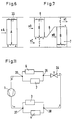
- the speed of the air flowing through the evaporator is denoted by xA and must not exceed a maximum value of 2 m / s, so that water droplets that are excreted due to the cooling air in the evaporator are reliably prevented from being entrained with the air flow and thus in get the air duct for the conditioned air to the vehicle. Due to the dimensions of the air conditioner housing to be maintained, an enlargement of the free air cross section A of the evaporator is not possible, so that only a relatively small amount of air can be passed through at maximum air speed.
- the air speed is halved to the value xB and flows through the evaporator 7 at this speed.
- Different exemplary embodiments are shown schematically in FIGS. 8, 9 and 10.
- FIG. 11 shows the basic integration of a divided evaporator and divided condenser inside the refrigerator shown.
- the coolant comes from the pressure side of the compressor 1 via a refrigerant distributor head 37 to two condensers 3, 4, from there via a refrigerant junction 38 to the expansion valve 34, from there via a refrigerant distributor head 35 to two evaporators 6, 7 and from there via one Refrigerant junction 36 to the suction side of the compressor 1.
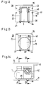
- FIGs 12, 13, 14 are fasteners for the compressor and access means to valves located on the compressor shown. Due to the extremely compact design of the Air conditioning unit is difficult to attach the compressor to the housing. Furthermore, access to the compressor is arranged Pressure and suction line shut-off valves difficult.
- mounting strips 39 are of this type double angled that one along the bottom of the Compressor 1 extending first leg, one at right angles thereto bent, extending from the bottom area to the lid area second leg and one bent at right angles to it Handle 43 result in the lid area.
- the mounting strips 39 can be made of solid material (steel, aluminum) in the first Legs cut threads for the compressor fastening screws 44 consist of sheet metal strips with rivet or weld nuts for the fastening screws become. It is important that the mounting strips 39 are bent such that the handle 43 in front of the free space or can be reached behind the compressor. That way it is possible to the compressor 1 with the help of the mounting strips 39 move inside the housing until the nuts / threaded holes of the compressor exactly over the corresponding bores lie in the bottom plate 21 and the assembly of the compressor by means Fastening screws 44 can be done.
- Figure 14 is the double-bent structure of the mounting bar 39 with first leg in the floor area, second Leg perpendicular to the floor area and handle 43 in the lid area to recognize.
- the compressor mounting screws 44 reach through the holes in the base plate 21 and the thread or the rivet or weld nuts in the mounting strips 39.
- the section planes of two sections are A-A and B-B. Section A-A is in Figure 13 and section B-B is shown in Figure 12. The location is in both cuts the mounting strips 39 with handles 43 and the compressor mounting screws 44 recognizable.
- assembly openings 41 are provided in the side walls 18, 22 of the housing. For this purpose, reference is made to FIGS. 12 and 14.
- the assembly openings 41 allow easy mounting of the fastening screws of the valves 40 with the compressor 1 installed, see above that an exchange of the compressor when compared to the compressor closed cooling circuit is possible. About wrong air currents The assembly openings are to be avoided during operation 41 closed by screwable cover 42.
- FIGS. 12 to 14 facilitate advantageous the assembly and replacement of the compressor 1 and are in a corresponding manner for other components of the Air conditioner can be used.
Landscapes
- Engineering & Computer Science (AREA)
- Mechanical Engineering (AREA)
- Physics & Mathematics (AREA)
- Thermal Sciences (AREA)
- Automation & Control Theory (AREA)
- Transportation (AREA)
- Chemical & Material Sciences (AREA)
- Combustion & Propulsion (AREA)
- General Engineering & Computer Science (AREA)
- Air-Conditioning For Vehicles (AREA)
- Air Humidification (AREA)
- Air-Conditioning Room Units, And Self-Contained Units In General (AREA)
Description
- Figur 1
- eine Sicht auf ein geöffnetes Kompaktklimagerät,
- Figur 2
- eine Sicht auf ein geschlossenes Kompaktklimagerät,
- Figur 3
- eine Seitenansicht eines Kompaktklimagerätes,
- Figur 4, 5
- zwei Varianten hinsichtlich der Gehäuseausführung,
- Figur 6
- die Luftführungsverhältnisse innerhalb eines Verdampfers bei konventioneller Technik,
- Figur 7
- die Luftführungsverhältnisse bei einem geteilten Verdampfer,
- Figur 8, 9, 10
- unterschiedliche Ausführungsbeispiele,
- Figur 11
- die prinzipielle Einbindung von geteiltem Verdampfer und geteiltem Verflüssiger,
- Figur 12, 13, 14
- Befestigungsmittel für den Verdichter und Zugangsmittel zu am Verdichter angeordneten Ventilen.
Claims (6)
- Kompaktklimagerät mit Verdampfer (6,7), Verdichter, Verflüssiger (3,4), Expansionsventil (3,4), Klimalüfter (10) und Verflüssigerlüfter (2), dadurch gekennzeichnet, daß Verdampfer (6,7) und/oder Verflüssiger (3,4) aus jeweils mindestens zwei getrennten Aggregaten zusammengesetzt sind, wobei die getrennten Aggregate derart versetzt hintereinander angeordnet sind, daß ein erster Teilluftstrom mit vorgegebener Luftgeschwindigkeit durch das erste Aggregat und ein zweiter Teilluftstrom mit hierzu erhöhter Luftgeschwindigkeit am ersten Aggregat vorbei und von dort mit vorgegebener Luftgeschwindigkeit durch das zweite Aggregat strömt und wobei die mindestens zwei getrennten Aggregate den gleichen Strömungswiderstand aufweisen.
- Kompaktklimagerät nach Anspruch 1, dadurch gekennzeichnet, daß ein Luftleitblech (8,5) zwischen den versetzt hintereinander angeordneten Aggregaten angeordnet ist.
- Kompaktklimagerät nach Anspruch 1 und/oder 2, dadurch gekennzeichnet, daß sich das Verhältnis der beiden Luftquerschnitte (B,C) für den ersten und den zweiten Teilluftstrom im Bereich zwischen 2:1 und 4:1 bewegt.
- Kompaktklimagerät nach einem der Ansprüche 1 bis 3, dadurch gekennzeichnet, daß zwischen Expansionsventil (34) und den Verdampfern (6,7) und/oder zwischen Verdichter (1) und den Verflüssigern (3,4) ein Kältemittel-Verteilerkopf (35 und/oder 37) angeordnet ist.
- Kompaktklimagerät nach einem der Ansprüche 1 bis 4, dadurch gekennzeichnet, daß die Montage von Baukomponenten, insbesondere die Montage des Verdichters (1) am Gehäuse über Befestigungsleisten (39) erfolgt, die ein Verschieben der Baukomponenten innerhalb des Gehäuses erleichtern.
- Kompaktklimagerät nach einem der Ansprüche 1 bis 5, dadurch gekennzeichnet, daß verschließbare Montageöffnungen (41) am Gehäuse vorgesehen sind, die die Zugänglichkeit zu Baukomponenten, insbesondere zu am Verdichter (1) angeordneten Befestigungsschrauben der Ventile (40) erleichtern.
Applications Claiming Priority (4)
| Application Number | Priority Date | Filing Date | Title |
|---|---|---|---|
| DE4400643 | 1994-01-12 | ||
| DE4400643 | 1994-01-12 | ||
| DE4414035 | 1994-04-22 | ||
| DE4414035A DE4414035A1 (de) | 1994-01-12 | 1994-04-22 | Kompaktklimagerät |
Publications (3)
| Publication Number | Publication Date |
|---|---|
| EP0663572A2 EP0663572A2 (de) | 1995-07-19 |
| EP0663572A3 EP0663572A3 (de) | 1997-06-04 |
| EP0663572B1 true EP0663572B1 (de) | 1999-12-08 |
Family
ID=25932958
Family Applications (1)
| Application Number | Title | Priority Date | Filing Date |
|---|---|---|---|
| EP95100168A Expired - Lifetime EP0663572B1 (de) | 1994-01-12 | 1995-01-07 | Kompaktklimagerät |
Country Status (3)
| Country | Link |
|---|---|
| EP (1) | EP0663572B1 (de) |
| AT (1) | ATE187398T1 (de) |
| ES (1) | ES2142959T3 (de) |
Cited By (1)
| Publication number | Priority date | Publication date | Assignee | Title |
|---|---|---|---|---|
| DE102005021396A1 (de) * | 2005-05-04 | 2006-11-09 | Behr Gmbh & Co. Kg | Vorrichtung zur Luftkonditionierung für ein Kraftfahrzeug |
Families Citing this family (3)
| Publication number | Priority date | Publication date | Assignee | Title |
|---|---|---|---|---|
| JP5868088B2 (ja) * | 2011-09-15 | 2016-02-24 | 株式会社ケーヒン・サーマル・テクノロジー | 車両用空調装置のクーリングユニット |
| US9835353B2 (en) * | 2011-10-17 | 2017-12-05 | Lennox Industries Inc. | Energy recovery ventilator unit with offset and overlapping enthalpy wheels |
| US20140311175A1 (en) * | 2013-04-19 | 2014-10-23 | Lg Electronics Inc. | Air conditioner |
Family Cites Families (1)
| Publication number | Priority date | Publication date | Assignee | Title |
|---|---|---|---|---|
| US4607497A (en) * | 1983-12-20 | 1986-08-26 | Suetrak U.S.A. | Roof-mounted air conditioner system having modular evaporator and condensor units |
-
1995
- 1995-01-07 AT AT95100168T patent/ATE187398T1/de not_active IP Right Cessation
- 1995-01-07 EP EP95100168A patent/EP0663572B1/de not_active Expired - Lifetime
- 1995-01-07 ES ES95100168T patent/ES2142959T3/es not_active Expired - Lifetime
Cited By (1)
| Publication number | Priority date | Publication date | Assignee | Title |
|---|---|---|---|---|
| DE102005021396A1 (de) * | 2005-05-04 | 2006-11-09 | Behr Gmbh & Co. Kg | Vorrichtung zur Luftkonditionierung für ein Kraftfahrzeug |
Also Published As
| Publication number | Publication date |
|---|---|
| ATE187398T1 (de) | 1999-12-15 |
| EP0663572A2 (de) | 1995-07-19 |
| ES2142959T3 (es) | 2000-05-01 |
| EP0663572A3 (de) | 1997-06-04 |
Similar Documents
| Publication | Publication Date | Title |
|---|---|---|
| DE19641635C2 (de) | Auf dem Dach montiertes Klimagerät | |
| DE4013036A1 (de) | Klimaanlage zum anbau am dach eines fahrzeugs | |
| DE4002909C2 (de) | Klimaanlage für Omnibusse | |
| EP3313678B1 (de) | Verdampfereinheit für eine aufdachklimaanlage eines strassenfahrzeugs | |
| EP3313677B1 (de) | Kondensatoreinheit einer aufdachklimaanlage | |
| DE4118745C2 (de) | Klimakompaktgerät für Fahrzeuge | |
| DE102012018537A1 (de) | Fahrzeugklimaanlage | |
| DE19750381B4 (de) | Kraftfahrzeug-Klimaanlage | |
| EP0663572A2 (de) | Kompaktklimagerät | |
| DE102004059680B4 (de) | Bauanordnung für Einrichtungen zum Austausch von Wärme | |
| DE10231395B4 (de) | Kraftfahrzeug-Kühlsystem | |
| DE102021002168B4 (de) | Klimatisierungs-Dachmodul | |
| DE102006009162B4 (de) | Heizungs-, Lüftungs- und Klimatisierungsanlage für Kraftfahrzeuge | |
| DE4414035A1 (de) | Kompaktklimagerät | |
| EP4334146B1 (de) | Klimatisierungsanordnung für einen innenraum eines fahrzeugs | |
| DE8622360U1 (de) | Fahrzeug, insbesondere Omnibus, mit einem für eine Klimaanlage vorgesehenen Dachaufbau | |
| DE1580731A1 (de) | Klimaanlage fuer Kraftfahrzeuge | |
| EP1434709A1 (de) | Lüftungssystem für fahrzeuge | |
| DE102016110604B4 (de) | Klimaanlage mit verbesserter Luftleitung und Verfahren dazu | |
| DE10032677C2 (de) | Kondensatoranordnung einer Klimaanlage, insbesondere in einem Kraftfahrzeug | |
| DE112024001439T5 (de) | Aggregatkühler | |
| EP1526016B1 (de) | Klimatisierungsvorrichtung, insbesondere für ein Kraftfahrzeug | |
| DE10315733A1 (de) | Vorrichtung zum Austausch von Wärme | |
| DE3911515C2 (de) | ||
| DE10344378A1 (de) | Komponentenanordnung einer Heiz-Klimaanlage |
Legal Events
| Date | Code | Title | Description |
|---|---|---|---|
| PUAI | Public reference made under article 153(3) epc to a published international application that has entered the european phase |
Free format text: ORIGINAL CODE: 0009012 |
|
| AK | Designated contracting states |
Kind code of ref document: A2 Designated state(s): AT DE ES FR GB IT |
|
| PUAL | Search report despatched |
Free format text: ORIGINAL CODE: 0009013 |
|
| AK | Designated contracting states |
Kind code of ref document: A3 Designated state(s): AT DE ES FR GB IT |
|
| RHK1 | Main classification (correction) |
Ipc: B60H 1/32 |
|
| 17P | Request for examination filed |
Effective date: 19970905 |
|
| RAP1 | Party data changed (applicant data changed or rights of an application transferred) |
Owner name: ABB DAIMLER-BENZ TRANSPORTATION (TECHNOLOGY) GMBH |
|
| GRAG | Despatch of communication of intention to grant |
Free format text: ORIGINAL CODE: EPIDOS AGRA |
|
| GRAG | Despatch of communication of intention to grant |
Free format text: ORIGINAL CODE: EPIDOS AGRA |
|
| GRAH | Despatch of communication of intention to grant a patent |
Free format text: ORIGINAL CODE: EPIDOS IGRA |
|
| 17Q | First examination report despatched |
Effective date: 19990517 |
|
| GRAH | Despatch of communication of intention to grant a patent |
Free format text: ORIGINAL CODE: EPIDOS IGRA |
|
| ITF | It: translation for a ep patent filed | ||
| GRAA | (expected) grant |
Free format text: ORIGINAL CODE: 0009210 |
|
| AK | Designated contracting states |
Kind code of ref document: B1 Designated state(s): AT DE ES FR GB IT |
|
| REF | Corresponds to: |
Ref document number: 187398 Country of ref document: AT Date of ref document: 19991215 Kind code of ref document: T |
|
| REF | Corresponds to: |
Ref document number: 59507353 Country of ref document: DE Date of ref document: 20000113 |
|
| GBT | Gb: translation of ep patent filed (gb section 77(6)(a)/1977) |
Effective date: 20000207 |
|
| ET | Fr: translation filed | ||
| REG | Reference to a national code |
Ref country code: ES Ref legal event code: FG2A Ref document number: 2142959 Country of ref document: ES Kind code of ref document: T3 |
|
| PLBE | No opposition filed within time limit |
Free format text: ORIGINAL CODE: 0009261 |
|
| STAA | Information on the status of an ep patent application or granted ep patent |
Free format text: STATUS: NO OPPOSITION FILED WITHIN TIME LIMIT |
|
| 26N | No opposition filed | ||
| REG | Reference to a national code |
Ref country code: FR Ref legal event code: TP Ref country code: FR Ref legal event code: CD |
|
| REG | Reference to a national code |
Ref country code: GB Ref legal event code: IF02 |
|
| PG25 | Lapsed in a contracting state [announced via postgrant information from national office to epo] |
Ref country code: IT Free format text: LAPSE BECAUSE OF NON-PAYMENT OF DUE FEES;WARNING: LAPSES OF ITALIAN PATENTS WITH EFFECTIVE DATE BEFORE 2007 MAY HAVE OCCURRED AT ANY TIME BEFORE 2007. THE CORRECT EFFECTIVE DATE MAY BE DIFFERENT FROM THE ONE RECORDED. Effective date: 20050107 |
|
| PGFP | Annual fee paid to national office [announced via postgrant information from national office to epo] |
Ref country code: ES Payment date: 20070321 Year of fee payment: 13 |
|
| PGFP | Annual fee paid to national office [announced via postgrant information from national office to epo] |
Ref country code: DE Payment date: 20070322 Year of fee payment: 13 |
|
| PGFP | Annual fee paid to national office [announced via postgrant information from national office to epo] |
Ref country code: AT Payment date: 20070323 Year of fee payment: 13 |
|
| PGFP | Annual fee paid to national office [announced via postgrant information from national office to epo] |
Ref country code: GB Payment date: 20070327 Year of fee payment: 13 |
|
| PGFP | Annual fee paid to national office [announced via postgrant information from national office to epo] |
Ref country code: IT Payment date: 20060131 Year of fee payment: 12 Ref country code: FR Payment date: 20070315 Year of fee payment: 13 |
|
| PGRI | Patent reinstated in contracting state [announced from national office to epo] |
Ref country code: IT Effective date: 20080301 |
|
| GBPC | Gb: european patent ceased through non-payment of renewal fee |
Effective date: 20080107 |
|
| PG25 | Lapsed in a contracting state [announced via postgrant information from national office to epo] |
Ref country code: DE Free format text: LAPSE BECAUSE OF NON-PAYMENT OF DUE FEES Effective date: 20080801 |
|
| PG25 | Lapsed in a contracting state [announced via postgrant information from national office to epo] |
Ref country code: AT Free format text: LAPSE BECAUSE OF NON-PAYMENT OF DUE FEES Effective date: 20080107 |
|
| REG | Reference to a national code |
Ref country code: FR Ref legal event code: ST Effective date: 20081029 |
|
| PG25 | Lapsed in a contracting state [announced via postgrant information from national office to epo] |
Ref country code: GB Free format text: LAPSE BECAUSE OF NON-PAYMENT OF DUE FEES Effective date: 20080107 |
|
| REG | Reference to a national code |
Ref country code: ES Ref legal event code: FD2A Effective date: 20080108 |
|
| PG25 | Lapsed in a contracting state [announced via postgrant information from national office to epo] |
Ref country code: FR Free format text: LAPSE BECAUSE OF NON-PAYMENT OF DUE FEES Effective date: 20080131 |
|
| PG25 | Lapsed in a contracting state [announced via postgrant information from national office to epo] |
Ref country code: ES Free format text: LAPSE BECAUSE OF NON-PAYMENT OF DUE FEES Effective date: 20080108 |
|
| PGRI | Patent reinstated in contracting state [announced from national office to epo] |
Ref country code: IT Effective date: 20080301 |