EP0659643B1 - Apparatus for grouping and packaging filled teabags - Google Patents
Apparatus for grouping and packaging filled teabags Download PDFInfo
- Publication number
- EP0659643B1 EP0659643B1 EP94117324A EP94117324A EP0659643B1 EP 0659643 B1 EP0659643 B1 EP 0659643B1 EP 94117324 A EP94117324 A EP 94117324A EP 94117324 A EP94117324 A EP 94117324A EP 0659643 B1 EP0659643 B1 EP 0659643B1
- Authority
- EP
- European Patent Office
- Prior art keywords
- row
- bags
- holder
- bag
- tea
- Prior art date
- Legal status (The legal status is an assumption and is not a legal conclusion. Google has not performed a legal analysis and makes no representation as to the accuracy of the status listed.)
- Expired - Lifetime
Links
- 238000004806 packaging method and process Methods 0.000 title claims description 6
- 241001122767 Theaceae Species 0.000 claims abstract description 28
- 230000015572 biosynthetic process Effects 0.000 claims description 4
- 230000000452 restraining effect Effects 0.000 claims description 2
- 238000010276 construction Methods 0.000 claims 2
- 238000012856 packing Methods 0.000 abstract description 3
- 238000011144 upstream manufacturing Methods 0.000 abstract description 3
- 230000008859 change Effects 0.000 description 3
- 238000003780 insertion Methods 0.000 description 2
- 230000037431 insertion Effects 0.000 description 2
- 238000012858 packaging process Methods 0.000 description 2
- 238000012546 transfer Methods 0.000 description 2
- 230000009471 action Effects 0.000 description 1
- 238000013016 damping Methods 0.000 description 1
- 238000011161 development Methods 0.000 description 1
- 230000018109 developmental process Effects 0.000 description 1
- 238000006073 displacement reaction Methods 0.000 description 1
- 238000009826 distribution Methods 0.000 description 1
- 230000000694 effects Effects 0.000 description 1
- 238000000034 method Methods 0.000 description 1
- 230000008569 process Effects 0.000 description 1
- 238000000926 separation method Methods 0.000 description 1
- 230000000087 stabilizing effect Effects 0.000 description 1
- 230000007704 transition Effects 0.000 description 1
- 238000009827 uniform distribution Methods 0.000 description 1
Images


Classifications
-
- B—PERFORMING OPERATIONS; TRANSPORTING
- B65—CONVEYING; PACKING; STORING; HANDLING THIN OR FILAMENTARY MATERIAL
- B65B—MACHINES, APPARATUS OR DEVICES FOR, OR METHODS OF, PACKAGING ARTICLES OR MATERIALS; UNPACKING
- B65B5/00—Packaging individual articles in containers or receptacles, e.g. bags, sacks, boxes, cartons, cans, jars
- B65B5/06—Packaging groups of articles, the groups being treated as single articles
- B65B5/061—Filled bags
Landscapes
- Engineering & Computer Science (AREA)
- Mechanical Engineering (AREA)
- Packages (AREA)
- Container Filling Or Packaging Operations (AREA)
- Auxiliary Devices For And Details Of Packaging Control (AREA)
Abstract
Description
Vorrichtung zum gruppenweisen Verpacken von gefüllten Teebeuteln mit einer durch einen Reihenhalter und einen Reihenschieber in einem Stapelschacht fixierten Beutelreihe, einem nachgeordneten Rotor mit wenigstens zwei Kassetten zur Aufnahme der fixierten Beutelreihe und einer aus einem weiteren Reihenhalter und Reihenschieber bestehenden Transporteinrichtung zum Transportieren der Beutelreihe aus der gedrehten Kassette über eine in Position gebrachte Schachtel.Device for the group packing of filled tea bags with a row of bags fixed by a row holder and a row slide in a stacking shaft, a downstream rotor with at least two cassettes for receiving the fixed row of bags and a transport device consisting of a further row holder and row slide for transporting the row of bags out of the rotated one Cassette over a positioned box.
Bei einer aus der DE-A-24 12 063 bekannten Vorrichtung der eingangs genannten Art werden die gefüllten Teebeutel aufrecht stehend auf einem Förderer herangeführt und mittels Abteilelementen in Gruppen vorbestimmter Anzahl abgeteilt und reihenweise durch den Reihenhalter und Reihenschieber erfaßt. Nach dem Überführen in die Kassette wird die Beutelreihe umgedreht, gerüttelt und zusammengedrückt, bevor sie dann in die bereitstehende Schachtel eingestoßen wird. Auf diese Weise soll erreicht werden, daß sich der Beutelinhalt weitgehend gleichmäßig verteilt und so verdichtet, daß die Beutelreihe in die bereitstehende Schachtel von vorbestimmter Länge paßt.In a device of the type mentioned at the beginning of DE-A-24 12 063, the filled tea bags are brought upright standing on a conveyor and divided into groups of predetermined numbers by means of compartment elements and recorded in rows by the row holder and row slide. After being transferred to the cassette, the row of bags is turned over, shaken and compressed before it is then pushed into the ready box. In this way, the aim is to ensure that the contents of the bag are largely evenly distributed and compressed so that the row of bags fits into the box of a predetermined length provided.
Eine derartige Vorrichtung ist in der Regel für das Verpacken gleichgroßer Beutelreihen mit einer vorbestimmten Anzahl von Teebeuteln ausgelegt. Um bei Bedarf die Anzahl der Teebeutel einer Beutelreihe dem jeweiligen Fassungsvermögen der eingesetzten Schachteln anzupassen, bedarf es langer Umrüstzeiten, was unerwünscht hohe Maschinenstandzeiten zur Folge hat. Hinzu kommt, daß sowohl bei einer Änderung der Beutelanzahl einer Beutelreihe als auch in Abhängigkeit von der Beschaffenheit des Teeguts sich ständig die Voraussetzungen für den Erhalt einer optimalen Verteilung des Beutelinhalts ändern, so daß bei hoher Maschinenleistung wenig Zeit bleibt, um die bekannte Vorrichtung den geänderten Gegebenheiten anzupassen. Störungen im Gesamtablauf sind daher selbst durch eine so aufwendige Maßnahme, wie das zusätzliche Rütteln der Teebeutel in den Kassetten, kaum zu vermeiden.Such a device is generally designed for packaging rows of bags of the same size with a predetermined number of tea bags. In order to adapt the number of tea bags in a row of bags to the respective capacity of the boxes used, long changeover times are required, which results in undesirably long machine downtimes. In addition, both when changing the number of bags in a row of bags and depending on the nature of the tea, the conditions for obtaining an optimal distribution of the Change the contents of the bag so that there is little time at high machine output to adapt the known device to the changed circumstances. Disruptions in the overall process can therefore hardly be avoided even by such a complex measure as the additional shaking of the tea bags in the cassettes.
Aus der DE-A-18 00 245 ist eine weitere Vorrichtung zur Bildung von Beutelgruppen und zur Einführung derselben in Schachteln bekannt, bei der die Beutel einer Gruppe abwechselnd aufrecht und auf dem Kopf stehend zusammengefaßt sind. Sie bilden somit zwar in der Schachtel eine kompakte und hochkante Gesamtform, die aber für den Kunden gewöhnungsbedüftig ist, da jeder zweite Teebeutel beim Herausnehmen auf dem Kopf steht. Auch bei dieser bekannten Vorrichtung sind Änderungen in der Gebindegröße nur unter großem Aufwand möglich.From DE-A-18 00 245 a further device for forming bag groups and for introducing them into boxes is known, in which the bags of a group are alternately grouped upright and upside down. They form a compact and upright overall shape in the box, but it takes getting used to for the customer, as every second tea bag is upside down when it is removed. With this known device, changes in the container size are only possible with great effort.
Aufgabe der vorliegenden Erfindung ist es daher, eine Vorrichtung der eingangs genannten Art zu schaffen, bei der eine Änderung der Gebindegröße zur optimalen Ausnutzung des Fassungsvermögens der Schachtel ohne weiteres möglich ist, wobei eine weitgehend gleichmäßige Teegutverteilung während des gesamten Verpackungsvorgangs erhalten bleibt.It is therefore an object of the present invention to provide a device of the type mentioned at the outset in which a change in the container size for optimal use of the capacity of the box is readily possible, with a largely uniform distribution of tea goods being maintained throughout the entire packaging process.
Die Aufgabe wird bei einer Vorrichtung der gattungsgemäßen Art durch die im Kennzeichen des Anspruches 1 genannten Merkmale gelöst.The object is achieved in a device of the generic type by the features mentioned in the characterizing part of claim 1.
Die mit der Erfindung erzielten Vorteile bestehen insbesondere darin, daß die Beutelreihe sich erst im Stapelschacht bildet, indem einzelne Beutel zugeführt und zu jeder Zeit zwischen den Rückhaltefingern und dem längsverschiebbaren Beutelhalter in einer aufrechten Lage gehalten bleiben. Auf diese Weise ist selbst bei hoher Maschinenleistung eine exakte Trennung und Fixierung der Beutel und Beutelreihen gewährleistet. Somit kann die Anzahl der Beutel einer Beutelreihe nach Bedarf beliebig verändert werden, ohne daß es dazu irgendwelcher zusätzlicher Maßnahmen oder Veränderungen an den vorhandenen Bauteilen der Vorrichtung bedarf. Zudem ist unabhängig vom Volumen des Teegutes und der Anzahl der vorgegebenen Beutel eine gleichbleibende und weitgehend drucklose Fixierung der Beutelreihe gewährleistet, was sich schonend sowohl auf das Teegut als auch auf das Beutelgut auswirkt. Dieser Zustand bleibt während des gesamten Verpackungsvorganges erhalten, so daß das Fassungsvermögen der Schachteln optimal genutzt werden kann.The advantages achieved by the invention are, in particular, that the row of bags only forms in the stacking shaft by feeding individual bags and keeping them in an upright position at all times between the retaining fingers and the longitudinally displaceable bag holder. In this way an exact separation and fixation of the bags and rows of bags is guaranteed even with high machine performance. Thus, the number of bags in a row of bags can be changed as required without the need for any additional measures or changes to the existing components of the device. In addition, regardless of the volume of the tea and the number of specified bags, a constant and largely pressure-free fixation of the bag row is guaranteed, which has a gentle effect on both the tea and the bag goods. This condition remains during the entire packaging process, so that the capacity of the boxes can be used optimally.
Vorteilhafte Ausgestaltungen der Erfindung sind in weiteren Ansprüchen angegeben. Die Weiterbildungen nach den Ansprüchen 2 bis 7 ermöglichen im wesentlichen einen zusätzlichen Stabilisierungseffekt bei der Reihenbildung bis zur Übernahme durch den Reihenhalter und Reihenschieber, die die Beutelreihe aus dem Stapelschacht in die nachgeschaltete Kassette überführt. Die Ansprüche 8 und 9 beinhalten konstruktive Maßnahmen an den Kassetten, wodurch auch im Übergangsbereich der Vorrichtung zwischen Bildung und Einstoßen einer Beutelreihe eine stabile Fixierung der Beutel erhalten bleibt und Leerzeiten vermieden werden. Die vorteilhaften Ausgestaltungen nach den Ansprüchen 10 und 11 ermöglichen schließlich, daß die erfindungsgemäße Vorrichtung an eine herkömmliche Teeverpackungsmaschine ankoppelbar ist, wobei weitgehend gewährleistet sein muß, daß durch die notwendige Änderung der Bewegungsbahn der mit hoher Geschwindigkeit entnommenen Beutel eine einseitige Verlagerung des Teegutes im Inneren des Beutels unterbleibt.Advantageous embodiments of the invention are specified in further claims. The further developments according to claims 2 to 7 essentially allow an additional stabilizing effect in the formation of rows until they are taken over by the row holder and row shifter, which transfers the row of bags from the stacking shaft into the downstream cassette.
Ein Ausführungsbeispiel der Erfindung ist in der Zeichnung dargestellt und wird im folgenden näher beschrieben.An embodiment of the invention is shown in the drawing and will be described in more detail below.
Es zeigen:
- Fig. 1
- eine Seitendarstellung der erfindungsgemäßen Vorrichtung in einem schematisierten Arbeitsablauf;
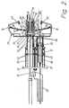
- Fig. 2
- die Vorrichtung nach Fig. 1 in Draufsicht;
- Fig. 3
- eine Schnittansicht entlang der Linie A-A nach Fig. 1 und
- Fig. 4
- eine Schnittansicht entlang der Linie B-B nach Fig. 1.
- Fig. 1
- a side view of the device according to the invention in a schematic workflow;
- Fig. 2
- the device of Figure 1 in plan view.
- Fig. 3
- a sectional view taken along line AA of FIG. 1 and
- Fig. 4
- 2 shows a sectional view along the line BB according to FIG. 1.
Die in der Zeichnung schematisch dargestellte Vorrichtung besitzt einen in Form einer Rinne mit rechteckförmigem Querschnitt ausgebildeten Stapelschacht 10 zur Bildung und Aufnahme einer aus mehreren gefüllten Teebeutel 11 bestehenden Beutelreihe 12. Die Beutel 11 werden einzeln mit Hilfe einer zangenförmigen Greifeinrichtung 13 von einer vorgeschalteten Teepverpackungsmaschine bekannter Bauart (nicht dargestellt) übernommen und dem Stapelschacht 10 mittels eines Beutelvorbringers 14 zugeführt. Die Greifeinrichtung 13 arbeitet mit einer Auflageschiene 15 zusammen, die vor dem Stapelschacht 10 in Höhe seiner unteren Auflagefläche angeordnet ist. Im Inneren des Stapelschachtes 10 sind im Eingangsbereich seitlich zwei gegenüberliegende Rückhaltefinger 16 vorgesehen, die in Längsrichtung ortsfest und quer zur Längsrichtung nach außen federnd angeordnet sind und eine schräge Anlauffläche in Vorschubrichtung der Beutel 11 aufweisen. Zum Halten der Beutel 11 bzw. der Beutelreihe 12 in Vorschubrichtung ist ein Beutelhalter 17 vorgesehen, der zwei Arme 18 besitzt, die verschwenkbar bei 19 an einer ortsfesten Halterung 20 angelenkt sind. An den freien Enden der Arme 18 ist jeweils ein gabelförmiger Finger 21 vorgesehen, der am Ende einer in den Armen 18 geführten Kolbenstange 22 befestigt ist. Arm 18 und Kolbenstange 22 bilden eine Kolben-Zylinder-Einheit, die vorzugsweise an eine nicht dargestellte Druckluftquelle angeschlossen ist. Die Arme 18 des Beutelhalters 17 sind zwischen einer Ausgangsstellung, in der sie federbeaufschlagt an einem Anschlag 23 anliegen, und einer Endstellung verschwenkbar, die in Abhängigkeit von der Beutelanzahl veränderbar ist.The device shown schematically in the drawing has a
Die Finger 21, die in Arbeitsstellung ausgefahren sind und an gegenüberliegenden Stellen seitlich in den Stapelschacht 10 ragen, bilden zusammen mit den Rückhaltefingern 16 eine Beutelfixierung, die die Beutel 11 im Stapelschacht 10 in einer Lage aufrechtstehend und flächig aneinanderliegend zusammenhalten. Zur besseren seitlichen Fixierung der Beutel sind innen an den Seitenwänden des Stapelschachtes 10 zusätzliche Führungsleisten 24 vorgesehen. An jedem Finger 21 ist jeweils ein Gleitelement 25 befestigt, das mit seiner kopfseitigen Stirnfläche gegenüber den Fingerspitzen zurückgesetzt ist und im ausgefahrenen Zustand der Finger 21 an einer Bremsleiste 26 an der Außenwand des Stapelschachtes 10 anliegt. Die Bremsleiste 26 erstreckt sich annähernd über die gesamte Länge des Stapelschachtes 10 und weist eine vorzugsweise aus Kunststoff bestehende Gleitfläche 27 auf, die in bezug zum Anlenkpunkt 19 der Arme 18 kreisbogenförmig ausgebildet ist. Im Bereich der Ausgangsstellung der Arme 18 ist die Gleitfläche 27 mit vorzugsweise mehreren Querrillen 28 versehen, die in Breite und Tiefe derart geformt sind, daß das Gleitelement 25 leicht einrasten kann.The
Zur Übernahme der fertigen Beutelreihe 12 im Stapelschacht 10 ist ein Reihenhalter 29 und ein Reihenschieber 30 vorgesehen, die vorzugsweise an eine Druckluftquelle (nicht dargestellt) angeschlossen sind und die sich in Ruhestellung außerhalb des Stapelschachtes 10 befinden. Der Reihenhalter 29 wird mittels einer Kolbenstange 31 entgegen der Vorschubrichtung der Beutel 11 in den Stapelschacht 10 eingefahren, während die Gegenbewegung des Reihenschiebers 30 über eine Hebelanordnung 32 gesteuert wird.To take over the finished row of
Dem Stapelschacht 10 ist ein mit 33 bezeichneter Rotor nachgeordnet, auf dem diametral zwei zur Rotorachse 34 versetzt angeordnete Kassetten 35, 36 untergebracht sind (Fig. 4). In der in Fig. 1 gezeigten Arbeitsstellung fluchtet die Kassette 35 mit dem Stapelschacht 10, während die Kassette 36 sich in einer Position befindet, in der sie mit einer aus einem weiteren Reihenhalter 37 und Reihenschieber 38 bestehenden Transporteinrichtung ausgerichtet ist, die vorzugsweise ebenfalls pneumatisch betätigbar ist. In den Kassetten 35, 36 sind paarweise seitliche Halter 39, 40 vorgesehen, von denen das vordere Halterpaar 39 im Aufbau und in der Funktionsweise den Rückhaltefingern 16 entspricht, während das hintere Halterpaar 40 in Längsrichtung einstellbar ist. Die beiden Halterpaare 39, 40 halten die Beutelreihe 12 während der Drehung der Kassetten positioniert. Die Transporteinrichtung 37, 38 schiebt die Beutelreihe 12 über eine ausgangsseitig der Kassette 36 in Position gebrachte Schachtel 41, oberhalb der sich ein Einstößer 42 befindet.The
Die Arbeitsweise der erfindungsgemäßen Vorrichtung ist wie folgt:The operation of the device according to the invention is as follows:
Die durch die Greifeinrichtung 13 einzeln auf der Auflageschiene 15 auf dem Kopf stehend abgesetzten Teebeutel 11 werden mit Hilfe des Beutelvorbringers 14 über die Anlaufschräge der Rückhaltefinger 16 in den Stapelschacht 10 gedrückt, wo sie durch die seitlich in den Stapelschacht 10 ragenden Finger 21 des in Ausgangsstellung befindlichen Beutelhalters 17 in aufrechter Lage fixiert werden. Fehlbeutel werden nach der Übergabe durch die Greifeinrichtung 13 vor Einstoßen in den Stapelschacht mittels einer Weiche und unter Einsatz von Druckluft ausgeschieden. Die beim Beschicken des Stapelschachtes 10 zu überwindenden Reibungskräfte des Beutelhalters 17 sind so eingestellt, daß nur während des Hinzukommens eines neuen Beutels kurzzeitig Druck auf die Beutelreihe ausgeübt wird, ansonsten aber eine gleichbleibende und weitgehend drucklose Fixierung der Beutel 11 gewährleistet ist. Die Querrillen 28 in der Bremsleiste 26 im Bereich der Ausgangsstellung des Beutelhalters 17 sorgen dafür, daß im Anfangsstadium der Reihenbildung die noch nicht ausreichende Eigendämpfung der Beutelreihe durch einen erhöhten Widerstand ersetzt wird. Ab einer vorbestimmten Beutelzahl übernimmt der Reihenhalter 29 übergangslos das Halten der Beutelreihe 12, so daß der Beutelhalter 17 vor Erreichen der vorgegebenen Beutelzahl pro Reihe in seine Ausgangsstellung zurückkehren kann. Sobald die gewünschte Beutelzahl pro Reihe erreicht ist, fährt der Reihenschieber 30 hinter den zuletzt gezählten Beutel und schiebt die gesamte Beutelreihe 12 gegen den reibungsgedämpften Reihenhalter 29 in eine bereitstehende Kassette 35, 36, in der die Halter 39, 40 die weitere Fixierung der Beutelreihe übernehmen. Unmittelbar nach Beginn der Übernahme beginnt sich im Stapelschacht zwischen den Rückhaltefingern 16 und dem Beutelhalter 17 eine neue Beutelreihe 12 zu bilden. Zur gleichen Zeit, wenn Reihenhalter 29 und Reihenschieber 30 die Kassette verlassen und in ihre Ausgangsstellung zurückkehren, beginnt sich der Rotor 33 zu drehen. Nachdem sich der Rotor 33 um 180 Grad gedreht hat, steht dem Stapelschacht 10 wieder eine freie Kassette zur Verfügung, während die nunmehr gedrehte und mit dem Beutelboden nach unten zeigende Beutelreihe 12 in der unteren Kassette durch den weiteren Reihenhalter 37 und Reihenschieber 38 übernommen und in eine Position oberhalb der bereitstehenden Schachtel 41 und unterhalb des Einstößers 42 geschoben wird. Der Einstößer fixiert die Beutelreihe seitlich und hält die Reihe während des Einstoßens fest. Erst in der Schachtel löst sich die Fixierung und der Einstößer fährt in seine Ausgangsstellung zurück.The
- 1010th
- StapelschachtStacking shaft
- 1111
- TeebeutelTeabag
- 1212th
- BeutelreiheRow of bags
- 1313
- GreifeinrichtungGripping device
- 1414
- BeutelvorbringerBag feeder
- 1515
- AuflageschieneSupport rail
- 1616
- RückhaltefingerRestraining fingers
- 1717th
- BeutelhalterBag holder
- 1818th
- Armpoor
- 1919th
- AnlenkpunktPivot point
- 2020th
- Halterungbracket
- 2121
- Fingerfinger
- 2222
- KolbenstangePiston rod
- 2323
- Anschlagattack
- 2424th
- FührungsleisteGuide bar
- 2525th
- GleitelementSliding element
- 2626
- BremsleisteBrake bar
- 2727
- GleitflächeSliding surface
- 2828
- QuerrillenCross grooves
- 2929
- ReihenhalterRow holder
- 3030th
- ReihenschieberRow slider
- 3131
- KolbenstangePiston rod
- 3232
- HebelanordnungLever arrangement
- 3333
- Rotorrotor
- 3434
- RotorachseRotor axis
- 3535
- Kassettecassette
- 3636
- Kassettecassette
- 3737
- ReihenhalterRow holder
- 3838
- ReihenschieberRow slider
- 3939
- Halterholder
- 4040
- Halterholder
- 4141
- Schachtelbox
- 4242
- EinstößerBumpers
Claims (11)
- Device for packaging filled tea bags in groups having a row of bags (12) fixed in a stacking shaft (10) by means of a row holder (29) and a row slider (30), a following rotor (33) with at least two cartridges (39, 36) for receiving the fixed row of bags and a transport device consisting of a further row holder (37) and row slider (38) for transporting the row of bags out of a rotated cartridge over a box (41) which is brought into position,
characterised in that
in the entrance region of the stacking shaft (10), together with a bag holder (17) displaceable during row formation in the longitudinal direction, two opposite, fixed restraining fingers (16) are additionally provided, between which the tea bags (11) fed individually through a bag advancer (14) are positioned before the row holder (29) takes over the holding of the row of bags from the bag holder (17), and that a pusher is provided for pushing the row of bags into the box. - Device according to Claim 1, characterised in that the bag holder (17) is friction damped and has two fingers (21) engaging at opposite positions laterally into the stacking shaft (10).
- Device according to Claim 2, characterised in that each finger (21) of the bag holder (17) is firmly connected to a sliding element (25) which, acted on by pressure, rests against a brake strip (26).
- Device according to Claim 3, characterised in that the brake strip (26) is of concave construction and in the forward region has at least one groove (28) running transversely.
- Device according to one of Claims 1 to 4, characterised in that the bag holder (17) is displaceable between a starting position and a specifiable end position, on reaching which it releases the row of bags (12) and returns to the starting position.
- Device according to one of Claims 1 to 5, characterised in that the row holder (29) provided in the stacking shaft (10) and the further row holder (37) of the transport device are friction damped.
- Device according to one of Claims 1 to 6, characterised in that in the interior of the stacking shaft (10) guide bars (24) running at the side are provided.
- Device according to one of Claims 1 to 7, characterised in that the two cartridges (35, 36) are arranged at an angular spacing offset with respect to the axis of rotation (34).
- Device according to Claim 8, characterised in that in the cartridges (35, 36) lateral holders (39, 40) are provided in pairs of which the front holder pair (39) is fixed in position and the rear holder pair (40) is adjustable in the longitudinal direction.
- Device according to one of Claims 1 to 9, characterised in that the bag advancer (14) is preceded by a tong-shaped grab device (13) which removes the tea bag (11) with head downwards from a tea packaging machine of known construction.
- Device according to Claim 10, characterised in that in the path of movement of the grab device (13) a bearing rail (15) is provided in front of the stacking shaft (10) at the level of its lower bearing surface.
Applications Claiming Priority (2)
| Application Number | Priority Date | Filing Date | Title |
|---|---|---|---|
| DE4342112 | 1993-12-10 | ||
| DE4342112A DE4342112C1 (en) | 1993-12-10 | 1993-12-10 | Apparatus for the groupwise packaging of filled teabags |
Publications (2)
| Publication Number | Publication Date |
|---|---|
| EP0659643A1 EP0659643A1 (en) | 1995-06-28 |
| EP0659643B1 true EP0659643B1 (en) | 1997-05-14 |
Family
ID=6504638
Family Applications (1)
| Application Number | Title | Priority Date | Filing Date |
|---|---|---|---|
| EP94117324A Expired - Lifetime EP0659643B1 (en) | 1993-12-10 | 1994-11-03 | Apparatus for grouping and packaging filled teabags |
Country Status (6)
| Country | Link |
|---|---|
| US (1) | US5548945A (en) |
| EP (1) | EP0659643B1 (en) |
| JP (1) | JP3719270B2 (en) |
| AT (1) | ATE152984T1 (en) |
| DE (2) | DE4342112C1 (en) |
| ES (1) | ES2103529T3 (en) |
Families Citing this family (11)
| Publication number | Priority date | Publication date | Assignee | Title |
|---|---|---|---|---|
| EP0791537A1 (en) * | 1996-02-22 | 1997-08-27 | Unilever Plc | Stack handling apparatus |
| IT1286753B1 (en) * | 1996-11-08 | 1998-07-17 | Tecnomeccanica Srl | DEVICE FOR FORMING, IN PACKAGING MACHINES, ORDERED SETS OF PRODUCTS AVAILABLE TO MUTUAL CONTACT AND INTRODUCING THEM INTO |
| EP0995702A1 (en) | 1998-10-23 | 2000-04-26 | The Procter & Gamble Company | Automatic handling device for flexible flat products, in particular catamenial products, and intermediate stacker unit to be used therein |
| ITBO20060422A1 (en) * | 2006-05-31 | 2007-12-01 | Ima Spa | AUTOMATIC PACKAGING MACHINE FOR THE PRODUCTION OF FILTER BAGS FOR INFUSION PRODUCTS |
| DE102008010432A1 (en) * | 2008-02-21 | 2009-08-27 | Focke & Co.(Gmbh & Co. Kg) | Method and device for inserting (hose) bags into cartons |
| US10144596B2 (en) | 2015-05-26 | 2018-12-04 | Dyco, Inc. | System and method for forming and moving an article array |
| US9586769B2 (en) * | 2015-05-26 | 2017-03-07 | Dyco, Inc. | System and method for forming and moving an article array |
| CN109436430B (en) * | 2018-12-14 | 2023-10-31 | 贵州西南工具(集团)有限公司 | Semi-automatic compressor sliding vane boxing device and boxing method |
| NL2023325B1 (en) * | 2019-06-17 | 2021-01-25 | Vmi Holland Bv | Container assembly for collecting pads, collector for receiving and collecting pads, punching device for manufacturing pads and method for collecting pads |
| EP4046916B1 (en) * | 2021-02-18 | 2023-07-19 | Teepack Spezialmaschinen GmbH & Co. KG | Method and device for forming packaging stacks |
| CN114955079B (en) * | 2022-05-07 | 2024-03-12 | 凯迈(洛阳)机电有限公司 | Multi-row tea bag stack summarizing mechanism, summarizing output method and summarizing output device |
Family Cites Families (16)
| Publication number | Priority date | Publication date | Assignee | Title |
|---|---|---|---|---|
| US2834164A (en) * | 1952-08-28 | 1958-05-13 | Nat Tea Packing Co Inc | Manufacture of filled packages with string-handles in predetermined counted output groups |
| US2941676A (en) * | 1954-02-17 | 1960-06-21 | Riegel Paper Corp | Apparatus for handling flexible walled bags |
| US2860460A (en) * | 1954-02-23 | 1958-11-18 | Teepack Spezialmaschinen G M B | Cartoning device |
| GB1097842A (en) * | 1965-09-21 | 1968-01-03 | Salomon Jacob | Method and apparatus for packaging bags |
| US3435584A (en) * | 1966-06-14 | 1969-04-01 | Domino Sugar Co | Packaging machine |
| DE1800245A1 (en) * | 1967-10-03 | 1969-10-16 | Azionaria Costruzioni | Device for forming groups of bags and for introducing them into boxes |
| GB1335223A (en) * | 1970-12-22 | 1973-10-24 | Salomon J | Packaging apparatus |
| US3812643A (en) * | 1972-08-31 | 1974-05-28 | Pneumatic Scale Corp | Semi-automatic machine for packaging tea bags |
| US3815316A (en) * | 1973-03-13 | 1974-06-11 | Delamere & Williams Co Ltd | Method and apparatus for loading tea bags into cartons |
| US4052838A (en) * | 1976-05-04 | 1977-10-11 | Frito-Lay, Inc. | Apparatus for packaging nested, uniformly shaped articles |
| DE2961405D1 (en) * | 1978-03-30 | 1982-01-28 | Conorelec | Packaging device and process therefor |
| CH630576A5 (en) * | 1978-05-29 | 1982-06-30 | Bernhard Steinbrecher | METHOD AND SYSTEM FOR THE AUTOMATIC PACKING OF STACKS OF ARTICLES. |
| CH632203A5 (en) * | 1978-08-22 | 1982-09-30 | Sig Schweiz Industrieges | DEVICE FOR CONSTANT WEIGHTING OF PACKAGES. |
| NL8001469A (en) * | 1980-03-12 | 1981-10-01 | Bouwe Prakken | Apparatus for packaging boxes of closed bags filled with product. |
| US4590743A (en) * | 1984-12-03 | 1986-05-27 | Food Machinery Sales, Inc. | Tray loading method and apparatus |
| DE3809039C1 (en) * | 1988-03-15 | 1989-09-14 | F. Zimmermann & Co, 1000 Berlin, De |
-
1993
- 1993-12-10 DE DE4342112A patent/DE4342112C1/en not_active Expired - Fee Related
-
1994
- 1994-11-03 EP EP94117324A patent/EP0659643B1/en not_active Expired - Lifetime
- 1994-11-03 ES ES94117324T patent/ES2103529T3/en not_active Expired - Lifetime
- 1994-11-03 DE DE59402747T patent/DE59402747D1/en not_active Expired - Lifetime
- 1994-11-03 AT AT94117324T patent/ATE152984T1/en not_active IP Right Cessation
- 1994-11-17 JP JP31898194A patent/JP3719270B2/en not_active Expired - Lifetime
- 1994-12-09 US US08/353,113 patent/US5548945A/en not_active Expired - Lifetime
Also Published As
| Publication number | Publication date |
|---|---|
| DE4342112C1 (en) | 1995-02-02 |
| JPH07205902A (en) | 1995-08-08 |
| DE59402747D1 (en) | 1997-06-19 |
| ATE152984T1 (en) | 1997-05-15 |
| JP3719270B2 (en) | 2005-11-24 |
| EP0659643A1 (en) | 1995-06-28 |
| ES2103529T3 (en) | 1997-09-16 |
| US5548945A (en) | 1996-08-27 |
Similar Documents
| Publication | Publication Date | Title |
|---|---|---|
| DE1561993C3 (en) | Device for stacking and packaging rod-shaped objects | |
| EP0311830B1 (en) | Method and device for packaging groups of single packages | |
| DE2003594C3 (en) | Device for spinning machines for evenly aligning and placing frustoconical bobbin tubes on the pins of a horizontally running conveyor | |
| EP0275481B2 (en) | Method and device for packaging paper handkerchiefs | |
| DE3123496C2 (en) | ||
| DE3736868C2 (en) | ||
| DE10201182A1 (en) | positioning | |
| EP0659643B1 (en) | Apparatus for grouping and packaging filled teabags | |
| EP1952705A2 (en) | Emptying cartridge and method for emptying shaft chamfers filled with rod-shaped products | |
| DE3521942C2 (en) | Device for producing groups of cigarettes in which there are gaps | |
| DE1980633U (en) | CIGARETTE PACKAGING MACHINE. | |
| DE3805093C1 (en) | ||
| DE3715570C2 (en) | ||
| DE2204268C3 (en) | Device for forming groups of cigarettes in a cigarette packing machine | |
| EP0393235B1 (en) | Device for collecting and depositing signatures | |
| DE10137843A1 (en) | Device for sorting and transporting bulk goods | |
| DE19746141A1 (en) | Method and device for wrapping articles of the tobacco processing industry into packaging material blanks | |
| EP0538742A1 (en) | Storage for goods pieces | |
| DE3104183A1 (en) | DEVICE FOR CONVEYING PARTIAL AMOUNTS OF BISKUITS | |
| DE3221620A1 (en) | DEVICE FOR ATTACHING COMPONENTS | |
| CH679924A5 (en) | ||
| EP0192116B1 (en) | Lateral folding packing device for soft cigarette packages | |
| DE2718338A1 (en) | Palletising system for rectangular items - has two packing plates used alternately to assemble layers for scraping onto pallet | |
| DE3543232A1 (en) | DEVICE FOR THE SUPPLY OF THE CIGARETTES FOR THE COVERING SECTION OF A PACKING MACHINE | |
| DE2809577C2 (en) | Device for conveying groups of elongated objects, in particular groups of cigarettes |
Legal Events
| Date | Code | Title | Description |
|---|---|---|---|
| PUAI | Public reference made under article 153(3) epc to a published international application that has entered the european phase |
Free format text: ORIGINAL CODE: 0009012 |
|
| AK | Designated contracting states |
Kind code of ref document: A1 Designated state(s): AT BE CH DE DK ES FR GB GR IE IT LI LU MC NL PT SE |
|
| RAX | Requested extension states of the european patent have changed |
Free format text: SI PAYMENT 941103 |
|
| 17P | Request for examination filed |
Effective date: 19950519 |
|
| GRAG | Despatch of communication of intention to grant |
Free format text: ORIGINAL CODE: EPIDOS AGRA |
|
| GRAH | Despatch of communication of intention to grant a patent |
Free format text: ORIGINAL CODE: EPIDOS IGRA |
|
| 17Q | First examination report despatched |
Effective date: 19961015 |
|
| GRAH | Despatch of communication of intention to grant a patent |
Free format text: ORIGINAL CODE: EPIDOS IGRA |
|
| GRAA | (expected) grant |
Free format text: ORIGINAL CODE: 0009210 |
|
| AK | Designated contracting states |
Kind code of ref document: B1 Designated state(s): AT BE CH DE DK ES FR GB GR IE IT LI LU MC NL PT SE |
|
| AX | Request for extension of the european patent |
Free format text: SI PAYMENT 941103 |
|
| PG25 | Lapsed in a contracting state [announced via postgrant information from national office to epo] |
Ref country code: GR Free format text: LAPSE BECAUSE OF FAILURE TO SUBMIT A TRANSLATION OF THE DESCRIPTION OR TO PAY THE FEE WITHIN THE PRESCRIBED TIME-LIMIT Effective date: 19970514 Ref country code: DK Effective date: 19970514 |
|
| REF | Corresponds to: |
Ref document number: 152984 Country of ref document: AT Date of ref document: 19970515 Kind code of ref document: T |
|
| REG | Reference to a national code |
Ref country code: CH Ref legal event code: EP |
|
| ET | Fr: translation filed | ||
| GBT | Gb: translation of ep patent filed (gb section 77(6)(a)/1977) |
Effective date: 19970515 |
|
| REF | Corresponds to: |
Ref document number: 59402747 Country of ref document: DE Date of ref document: 19970619 |
|
| PG25 | Lapsed in a contracting state [announced via postgrant information from national office to epo] |
Ref country code: SE Effective date: 19970814 Ref country code: PT Effective date: 19970814 |
|
| REG | Reference to a national code |
Ref country code: ES Ref legal event code: FG2A Ref document number: 2103529 Country of ref document: ES Kind code of ref document: T3 |
|
| PG25 | Lapsed in a contracting state [announced via postgrant information from national office to epo] |
Ref country code: LU Free format text: LAPSE BECAUSE OF NON-PAYMENT OF DUE FEES Effective date: 19971103 |
|
| PG25 | Lapsed in a contracting state [announced via postgrant information from national office to epo] |
Ref country code: LI Free format text: LAPSE BECAUSE OF NON-PAYMENT OF DUE FEES Effective date: 19971130 Ref country code: CH Free format text: LAPSE BECAUSE OF NON-PAYMENT OF DUE FEES Effective date: 19971130 |
|
| PLBE | No opposition filed within time limit |
Free format text: ORIGINAL CODE: 0009261 |
|
| STAA | Information on the status of an ep patent application or granted ep patent |
Free format text: STATUS: NO OPPOSITION FILED WITHIN TIME LIMIT |
|
| PG25 | Lapsed in a contracting state [announced via postgrant information from national office to epo] |
Ref country code: IE Free format text: LAPSE BECAUSE OF NON-PAYMENT OF DUE FEES Effective date: 19980330 |
|
| REG | Reference to a national code |
Ref country code: IE Ref legal event code: FD4D Ref document number: 73981 Country of ref document: IE |
|
| 26N | No opposition filed | ||
| PG25 | Lapsed in a contracting state [announced via postgrant information from national office to epo] |
Ref country code: MC Free format text: LAPSE BECAUSE OF NON-PAYMENT OF DUE FEES Effective date: 19980531 |
|
| REG | Reference to a national code |
Ref country code: CH Ref legal event code: PL |
|
| REG | Reference to a national code |
Ref country code: GB Ref legal event code: IF02 |
|
| PGFP | Annual fee paid to national office [announced via postgrant information from national office to epo] |
Ref country code: AT Payment date: 20021029 Year of fee payment: 9 |
|
| PG25 | Lapsed in a contracting state [announced via postgrant information from national office to epo] |
Ref country code: AT Free format text: LAPSE BECAUSE OF NON-PAYMENT OF DUE FEES Effective date: 20031103 |
|
| PGFP | Annual fee paid to national office [announced via postgrant information from national office to epo] |
Ref country code: FR Payment date: 20131120 Year of fee payment: 20 Ref country code: GB Payment date: 20131120 Year of fee payment: 20 |
|
| PGFP | Annual fee paid to national office [announced via postgrant information from national office to epo] |
Ref country code: IT Payment date: 20131128 Year of fee payment: 20 Ref country code: ES Payment date: 20131128 Year of fee payment: 20 Ref country code: NL Payment date: 20131121 Year of fee payment: 20 Ref country code: BE Payment date: 20131121 Year of fee payment: 20 |
|
| PGFP | Annual fee paid to national office [announced via postgrant information from national office to epo] |
Ref country code: DE Payment date: 20140124 Year of fee payment: 20 |
|
| REG | Reference to a national code |
Ref country code: DE Ref legal event code: R071 Ref document number: 59402747 Country of ref document: DE |
|
| REG | Reference to a national code |
Ref country code: NL Ref legal event code: V4 Effective date: 20141103 |
|
| REG | Reference to a national code |
Ref country code: GB Ref legal event code: PE20 Expiry date: 20141102 |
|
| PG25 | Lapsed in a contracting state [announced via postgrant information from national office to epo] |
Ref country code: GB Free format text: LAPSE BECAUSE OF EXPIRATION OF PROTECTION Effective date: 20141102 |
|
| REG | Reference to a national code |
Ref country code: ES Ref legal event code: FD2A Effective date: 20150826 |
|
| PG25 | Lapsed in a contracting state [announced via postgrant information from national office to epo] |
Ref country code: ES Free format text: LAPSE BECAUSE OF EXPIRATION OF PROTECTION Effective date: 20141104 |