EP0658775B1 - Kollisionsschutzeinrichtung für Kraftfahrzeuge - Google Patents
Kollisionsschutzeinrichtung für Kraftfahrzeuge Download PDFInfo
- Publication number
- EP0658775B1 EP0658775B1 EP94402842A EP94402842A EP0658775B1 EP 0658775 B1 EP0658775 B1 EP 0658775B1 EP 94402842 A EP94402842 A EP 94402842A EP 94402842 A EP94402842 A EP 94402842A EP 0658775 B1 EP0658775 B1 EP 0658775B1
- Authority
- EP
- European Patent Office
- Prior art keywords
- obstacle
- collision
- antennas
- risk
- moving object
- Prior art date
- Legal status (The legal status is an assumption and is not a legal conclusion. Google has not performed a legal analysis and makes no representation as to the accuracy of the status listed.)
- Expired - Lifetime
Links
Images


Classifications
-
- G—PHYSICS
- G01—MEASURING; TESTING
- G01S—RADIO DIRECTION-FINDING; RADIO NAVIGATION; DETERMINING DISTANCE OR VELOCITY BY USE OF RADIO WAVES; LOCATING OR PRESENCE-DETECTING BY USE OF THE REFLECTION OR RERADIATION OF RADIO WAVES; ANALOGOUS ARRANGEMENTS USING OTHER WAVES
- G01S13/00—Systems using the reflection or reradiation of radio waves, e.g. radar systems; Analogous systems using reflection or reradiation of waves whose nature or wavelength is irrelevant or unspecified
- G01S13/88—Radar or analogous systems specially adapted for specific applications
- G01S13/93—Radar or analogous systems specially adapted for specific applications for anti-collision purposes
- G01S13/931—Radar or analogous systems specially adapted for specific applications for anti-collision purposes of land vehicles
-
- G—PHYSICS
- G01—MEASURING; TESTING
- G01S—RADIO DIRECTION-FINDING; RADIO NAVIGATION; DETERMINING DISTANCE OR VELOCITY BY USE OF RADIO WAVES; LOCATING OR PRESENCE-DETECTING BY USE OF THE REFLECTION OR RERADIATION OF RADIO WAVES; ANALOGOUS ARRANGEMENTS USING OTHER WAVES
- G01S13/00—Systems using the reflection or reradiation of radio waves, e.g. radar systems; Analogous systems using reflection or reradiation of waves whose nature or wavelength is irrelevant or unspecified
- G01S13/02—Systems using reflection of radio waves, e.g. primary radar systems; Analogous systems
- G01S13/06—Systems determining position data of a target
- G01S13/46—Indirect determination of position data
- G01S13/48—Indirect determination of position data using multiple beams at emission or reception
-
- G—PHYSICS
- G01—MEASURING; TESTING
- G01S—RADIO DIRECTION-FINDING; RADIO NAVIGATION; DETERMINING DISTANCE OR VELOCITY BY USE OF RADIO WAVES; LOCATING OR PRESENCE-DETECTING BY USE OF THE REFLECTION OR RERADIATION OF RADIO WAVES; ANALOGOUS ARRANGEMENTS USING OTHER WAVES
- G01S13/00—Systems using the reflection or reradiation of radio waves, e.g. radar systems; Analogous systems using reflection or reradiation of waves whose nature or wavelength is irrelevant or unspecified
- G01S13/88—Radar or analogous systems specially adapted for specific applications
- G01S13/93—Radar or analogous systems specially adapted for specific applications for anti-collision purposes
- G01S13/931—Radar or analogous systems specially adapted for specific applications for anti-collision purposes of land vehicles
- G01S2013/9327—Sensor installation details
- G01S2013/93271—Sensor installation details in the front of the vehicles
-
- G—PHYSICS
- G01—MEASURING; TESTING
- G01S—RADIO DIRECTION-FINDING; RADIO NAVIGATION; DETERMINING DISTANCE OR VELOCITY BY USE OF RADIO WAVES; LOCATING OR PRESENCE-DETECTING BY USE OF THE REFLECTION OR RERADIATION OF RADIO WAVES; ANALOGOUS ARRANGEMENTS USING OTHER WAVES
- G01S13/00—Systems using the reflection or reradiation of radio waves, e.g. radar systems; Analogous systems using reflection or reradiation of waves whose nature or wavelength is irrelevant or unspecified
- G01S13/88—Radar or analogous systems specially adapted for specific applications
- G01S13/93—Radar or analogous systems specially adapted for specific applications for anti-collision purposes
- G01S13/931—Radar or analogous systems specially adapted for specific applications for anti-collision purposes of land vehicles
- G01S2013/9327—Sensor installation details
- G01S2013/93277—Sensor installation details in the lights
Definitions
- the present invention relates to an anti-collision device. She applies in particular to the equipment of motor vehicles for their avoid obstacles preceding them, in case of poor visibility for example. More generally it applies to all functions collision avoidance between a moving object and an obstacle.
- a first known system uses a millimeter radar, the antenna generally has an opening beam equal to approximately 2 to 3 degrees.
- This beam width means that at 100 m from the vehicle, the width at -3dB of the beam is about 5 m and at 200 m its width is about 10 m. With this last width, a lateral target not dangerous, such as a sign, can be lit by the beam and therefore cause a false alarm.
- the fineness of the beam means that a obstacle that could collide with this vehicle, may not be illuminated by the beam and therefore go unnoticed for the system anti-collision.
- a large rear load of the vehicle or a uneven terrain can raise the end of the beam in relation to obstacles preceding the vehicle, the latter then not being lit.
- Anti-collision optical systems are known. They are performing in clear weather but practically unusable in bad weather weather, rain or fog for example.
- US Patent 4,148,028 describes a device for avoiding collision between a vehicle and an obstacle.
- the object of the invention is to overcome the aforementioned drawbacks, in particular by making it possible to obtain reliable and reliable information on a risk of collision.
- the subject of the invention is a device as defined by the claim 1.
- the main advantages of the invention are that it operates by whatever the weather, that it adapts to all types of vehicles, that it is simple to implement and that it is economical.
- FIG. 1 shows, at a given time t 1 , a mobile object 1, a vehicle for example, circulating for example on a track and approaching an obstacle 3, another vehicle for example or any other type of possible obstacle .
- the mobile object 1 has a vector D oriented in the direction of its displacement and a speed vector V R towards the obstacle 3, the modulus of the speed vector expressing the relative speed between the latter and the mobile object 1.
- the vector D indicates the given direction in which the moving object 1 is moving.
- the relative speed vector V R and the displacement vector form between them a first angle ⁇ 1 .
- FIG. 1b shows the mobile object 1 and the obstacle 3 at an instant t 2 posterior to the previous instant t 1 , the mobile object 1 having come closer to the obstacle 3.
- the latter two now have a relative speed vector V R 'making a second angle ⁇ 2 with the displacement vector D of the mobile obstacle 1.
- V R the relative speed vector
- Figures 2a and 2b illustrate a case of risk of collision between the moving object 1 and the obstacle 3.
- FIG. 2a shows the relative positions of the mobile object 1 and of the obstacle 3 at a given first time t 1 .
- FIG. 2b presents their positions relating to a second instant t 2 after the previous one, the moving object having moved closer to the obstacle 3.
- the operating principle of the device according to the invention exploits in particular the fact that, when the moving object 1 is moving towards the obstacle 3 to the point of risking colliding with the latter, the relative speed vector V R pointing to a given point B of the obstacle 3, the angle ⁇ between the displacement vector D and the relative speed vector V R remains substantially constant during the approach between the moving object and the obstacle, the amplitude of the relative vector V R may vary.
- This constant angle ⁇ is illustrated by FIGS. 2a and 2b taken at two instants t 1 , t 2 during this approximation. In the case of FIGS. 1a and 1b where there is approximation without risk of collision, the angle ⁇ 2 of the instant t 2 is different from the angle ⁇ 1 of the previous instant t 1 .
- the device according to the invention uses at least two antennas A 1 , A 2 , represented by their relative positions in FIG. 3, these positions being able to be represented by dots due to the great distance separating the antennas from the obstacle. Furthermore, these points can represent for example the origin of the beams of the antennas A 1 , A 2 . These two antennas A 1 , A 2 each emit a microwave signal, the obstacle 3 being capable of returning an echo. In the case of application to a motor vehicle, these antennas are for example each placed at the level of a headlight. In the case where these two antennas A 1 , A 2 transmit for example simultaneously, they produce interference lobes 31.
- this point B returns energy E to reception means associated with the antennas A 1 , A 2 .
- the point B has a relative speed compared to a point A of the moving object, the relative speed being represented by a vector V R of origin in A and directed towards the point B, the point A was for example located in the middle of the two antennas A 1 , A 2 .
- This point A has a displacement vector D which is that of the mobile object 1.
- the relative speed vector V R makes an angle ⁇ with the displacement vector D.
- FIG. 4 illustrates the angles made by the aforementioned point B with the antennas A 1 , A 2 .
- the vector originating at the reference point of the first antenna A 1 and at the end B, makes an angle with an axis N passing through the reference point of the first antenna A 1 and parallel to the axis of symmetry S mentioned above which is substantially equal to the angle ⁇ previously defined between the relative speed vector V R and the displacement vector D because of the fact that the distance between the two antennas A 1 , A 2 and therefore the distance between the medium A of these antennas and the first antenna A 1 is very small compared to the distance of the antennas at point B of the obstacle;
- a 1 B - A 2 B constitutes the gait difference, it is equal to A 1 A 2 sin ⁇ , ⁇ being the angle previously defined.
- the energy E of the received echo can then be written:
- the angle ⁇ remains constant and therefore, at distance approximation effects contained in the first term in cosine of relation (5), the energy E of the received echo does not fluctuate. analysis of this energy E received by making it possible to analyze the variations of the angle ⁇ could predict the risk of collision.
- the first is that if the obstacle is located between the interference lobes 31, it is not identified by the means of detection associated with antennas and may therefore possibly not be avoid.
- the two antennas A 1 , A 2 for example transmit sequentially so that at all times the entire area contained inside the envelope 32 of the diagram of an antenna be lit. There are therefore no more interference lobes 31, therefore no more interference holes.
- the device according to the invention comprises means for keeping the instantaneous phase of the echoes received from the obstacle B following each antenna transmission, these means are for example distance extractors retaining the instantaneous phase of a received wave, which is achieved in particular by all Doppler radars. It is then possible to reconstruct an echo received from obstacle B, the phase of which remains associated with the distances A 1 B and A 2 B previously defined and therefore making it possible to obtain a signal which is a function of the angle ⁇ .
- the means for preserving the phase consist, for example, of means for correlating the echo received with a constant phase clock signal in a frequency modulation or phase jump radar.
- One of these means consists for example of a time gate of a pulse radar retaining the instantaneous phase at each recurrence of emission, this phase carrying the Doppler effect.
- the Doppler signal can be reconstructed from the samples for each antenna emission A 1 , A 2 in application of Shannon's theorem.
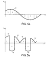
- Figures 5a and 5b show as a function of time, the amplitude Ad of the signals reconstructed from the samples received for each antenna emission in the case where the obstacle B belongs respectively to the place of an old interference lobe 31 or the place of an old hole interference.
- the signal 51 is reconstructed from samples, in phase, produced successively from the emission of one or the other antenna A 1 , A 2 , the signal samples from the first antenna A 1 being identified by portions comprising the number 1 and the signal samples from the second antenna A 2 being identified by portions comprising the number 2.
- the samples from the two antennas are then in phase opposition.
- the reconstructed signal 52 from the samples received then has the same surface on each side of the time axis t.
- This signal filtered by a low-pass filter under the switching frequency of the two antennas A 1 , A 2 therefore has a zero result.
- this signal filtered by a low-pass filter under the switching frequency of the two antennas A 1 , A 2 therefore has a zero result.
- this signal filtered by a low-pass filter under the switching frequency of the two antennas A 1 , A 2 therefore has a zero result.
- these are for example cut off from one another to obtain a non-zero signal after pass-filtering. low.
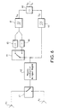
- Figure 6 shows a possible embodiment of the device according to the invention making it possible to obtain two signals So, S ⁇ after filtering lowpass.
- the first signal So is obtained by filtering the signal 51 reconstructed from Doppler samples in phase and the signal S ⁇ is obtained by filtering the signal 52 obtained from the Doppler samples in phase opposition but previously put back in phase by inversion of the sign, that is to say phase shift of ⁇ , of the signals coming from one of the antennas, and this in order to obtain a non-zero filtered signal.
- the two antennas A 1 , A 2 are connected to first switching means 61, the latter switching sequentially the echo samples received from the obstacle B by the first antenna A 1 and by the second A 2 .
- the output of the first switching means 61 is connected to means 62 for extracting the Doppler signals, which characterize the instantaneous phase of the echo samples received successively by one or the other antenna.
- the output of the Doppler signal extraction means is connected on the one hand to a first low-pass filter 63 whose output delivers the signal So and on the other hand to second switching means 64 whose switching is synchronous with the first switching means 61.
- the second switching means 64 have a first output connected to a first channel 65 which does not reverse its input signal and a second output connected to a second channel 66 which reverses its input signal, the two channels 65, 66 being connected together at their outputs to the input of a second low-pass filter 67 whose output delivers the signal S ⁇ .
- the initial positions of the switching means 61, 64 are for example adjusted so that the signals obtained at the inputs of the filters 63, 67 do not produce null signals at the output of the latter, but on the contrary signals not null, So, S ⁇ .
- the So / S ⁇ ratio of these signals is analyzed because it gives a good indication of the variation of the angle ⁇ previously defined, as well as of the value of this angle.
- the outputs of the filters 63, 67 are for example connected to means for dividing the energy of the signal So by the energy of the signal S ⁇ .
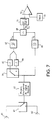
- FIG. 7 illustrates an example of implementation of the collision risk determination by completing the embodiment of Figure 6.
- the output of the division means 68 giving the ratio So / S ⁇ is connected to the input of means 71 of derivation with respect to time, which for example also give the absolute value of d (So / S ⁇ ) / dt .
- the latter is for example displayed at the negative input of comparison means 72, the positive input of which is linked to a threshold 73.
- the information obtained at the output of the comparison means 72 indicates the existence or not of a risk of collision, a positive signal indicating for example a risk of collision and a negative or zero signal, the absence of risk of collision.
- the value of the derivative signal d (So / S ⁇ ) / dt is an indicator, for each distance between the moving object 1 and the obstacle 3, of their lateral deviation.
- Figure 8 illustrates different lateral deviations.
- the threshold 73 previously defined to define the risk of collision can therefore be dependent on the distance to tolerate a constant lateral deviation between the moving object 1 and the obstacle 3, the value d (So / S ⁇ ) / dt being representative as a function the distance between the latter two from their lateral deviation.
- the definition of a lateral deviation below which a risk of collision is considered makes it possible in particular to improve the safety of the mobile object 1. This in particular makes it possible to overcome the effects of a conical beam, too narrow at short distance and too wide at a great distance.
- the value of the tolerated deviation can for example vary as a function of different parameters, linked to traffic conditions, relief conditions, environmental conditions or atmospheric conditions in particular.
- the device according to the invention can measure the speed of the obstacle as well as its distance from the moving object to refine the risk of collision.
- the anti-collision device according to the invention applies for example to motor vehicles. It can be applied to all types of objects mobile, aircraft for example.
- the obstacles to avoid can be all natures.
Landscapes
- Engineering & Computer Science (AREA)
- Radar, Positioning & Navigation (AREA)
- Remote Sensing (AREA)
- Physics & Mathematics (AREA)
- Electromagnetism (AREA)
- Computer Networks & Wireless Communication (AREA)
- General Physics & Mathematics (AREA)
- Radar Systems Or Details Thereof (AREA)
- Indicating Or Recording The Presence, Absence, Or Direction Of Movement (AREA)
- Traffic Control Systems (AREA)
Claims (7)
- Vorrichtung zur Vermeidung von Kollisionen zwischen einem beweglichen Objekt (1) und einem Hindernis (3, R), wobei das bewegliche Objekt sich in einer gegebenen Richtung gemäß einem Bewegungsvektor (D) bewegt und einen relativen Geschwindigkeitsvektor (VR) in Richtung zum Hindernis (3) besitzt, wobei die Vorrichtung mindestens zwei am beweglichen Objekt (1) angebrachte Antennen (A1, A2), die ein Hochfrequenzsignal aussenden, das auf das Hindernis (3) auftreffen kann, Mittel (A1, A2, 61, 62, 64, 65, 66) zum Empfang und Mittel (63, 67, 68, 71, 72, 73) zur Analyse der vom Hindernis (3) kommenden Echos sowie Analysemittel aufweist, die die zeitliche Veränderung des Winkels () zwischen dem Bewegungsvektor (D) und dem relativen Geschwindigkeitsvektor (VR) bestimmen, wobei eine Veränderung des Winkels () um einen Wert von im wesentlichen null eine Kollisionsgefahr anzeigt und die Antennen abwechselnd nacheinander senden, wobei die Vorrichtung weiter Mittel (62) zur Konservierung der augenblicklichen Phase der bei jeder Antennenaussendung empfangenen Echotastproben, sodaß ein Dopplersignal (51, 52) ausgehend von diesen empfangenen Tastproben erhalten wird, das eine Information über den Wert des Winkels () enthält, sowie erste Schaltmittel (61) zur Umschaltung der von den Antennen (A1, A2) empfangenen Signale enthält, deren Ausgang an Mittel (62) zur Erzeugung des Dopplersignals angeschlossen sind, dadurch gekennzeichnet, daß der Ausgang dieser Mittel einerseits mit einem ersten Tiefpaßfilter (63) und andrerseits mit zweiten Schaltmittels (64) verbunden ist, die mit den ersten Schaltmitteln (61) synchronisiert sind und das Dopplersignal abwechselnd an einen invertierenden Kanal (66) und einen nicht-invertierenden Kanal (65) leiten, wobei der nicht invertierende Kanal durchgeschaltet wird, wenn eine erste Antenne (A1) eingeschaltet ist, und der invertierende Kanal (66), wenn die andere Antenne (A2) eingeschaltet ist, wobei die beiden Kanäle (65, 66) mit ihren Ausgängen an den Eingang eines zweiten Tiefpaßfilters (67) angeschlossen sind und die Ausgänge der Filter (63, 67) an Mittel (68) zur Division des Ausgangssignals (So) des ersten Filters (63) durch das Ausgangssignmal (Sπ) des zweiten Filters (67) angeschlossen sind, sodaß das Verhältnis (So/Sπ) der Signale eine Information über den Wert des Winkels () enthält.
- Vorrichtung nach Anspruch 1, dadurch gekennzeichnet, daß die Antennen (A1, A2) als Sende- und Empfangsantennen dienen.
- Vorrichtung nach einem beliebigen der vorstehenden Ansprüche, dadurch gekennzeichnet, daß sie Mittel (71, 72, 73) zur Analyse des zeitlichen Differentials des Verhältnisses (So/Sπ) enthält, wobei die Unterschreitung einer Schwelle (73) des Absolutwerts des Differentials |d(So/Sπ)/dt| eine Kollisionsgefahr anzeigt.
- Vorrichtung nach einem beliebigen der vorstehenden Ansprüche, dadurch gekennzeichnet, daß der Ausgang der Divisionsmittel (68) an den Eingang von Differenziermitteln (71) angeschlossen ist, die den Absolutwert des zeitlichen Differentials des Verhältnisses (So/Sπ) liefern, wobei der Ausgang der Differenziermittel mit einem Schwellwert (73) über Vergleichsmittel (72) verglichen wird, deren Ausgang ein Signal liefert, das die Kollisionsgefahr bezeichnet.
- Vorrichtung nach einem beliebigen der Ansprüche 3 und 4, dadurch gekennzeichnet, daß die Schwelle (73) von der Entfernung zwischen dem beweglichen Objektes (1) und dem Hindernis (3) abhängt, um einen seitlichen Abstand zu definieren, innerhalb dem das Hindernis eine Kollisionsgefahr bedeutet.
- Vorrichtung nach einem beliebigen der vorstehenden Ansprüche, dadurch gekennzeichnet, daß das bewegliche Objekt ein Kraftfahrzeug ist und daß die Antennen (A1, A2) je in Höhe eines der vorderen Scheinwerfer des Fahrzeugs liegen.
- Vorrichtung nach einem beliebigen der vorstehenden Ansprüche, dadurch gekennzeichnet, daß sie die Geschwindigkeit des Hindernisses (3) und seine Entfernung zum beweglichen Objekt (1) mißt und daß diese Messungen mit der Messung des Winkels () kombiniert werden, um eine Kollisionsgefahr anzuzeigen.
Applications Claiming Priority (2)
| Application Number | Priority Date | Filing Date | Title |
|---|---|---|---|
| FR9314991 | 1993-12-14 | ||
| FR9314991A FR2713808B1 (fr) | 1993-12-14 | 1993-12-14 | Dispositif d'anticollision, notamment pour véhicules automobiles. |
Publications (2)
| Publication Number | Publication Date |
|---|---|
| EP0658775A1 EP0658775A1 (de) | 1995-06-21 |
| EP0658775B1 true EP0658775B1 (de) | 2000-02-23 |
Family
ID=9453898
Family Applications (1)
| Application Number | Title | Priority Date | Filing Date |
|---|---|---|---|
| EP94402842A Expired - Lifetime EP0658775B1 (de) | 1993-12-14 | 1994-12-09 | Kollisionsschutzeinrichtung für Kraftfahrzeuge |
Country Status (5)
| Country | Link |
|---|---|
| US (1) | US5534870A (de) |
| EP (1) | EP0658775B1 (de) |
| JP (1) | JPH07209418A (de) |
| DE (1) | DE69423079T2 (de) |
| FR (1) | FR2713808B1 (de) |
Families Citing this family (26)
| Publication number | Priority date | Publication date | Assignee | Title |
|---|---|---|---|---|
| SE516317C2 (sv) * | 1994-06-07 | 2001-12-17 | Saabtech Electronics Ab | Förfarande för att bestämma körfältet för ett framförvarande fordon |
| DE19537129A1 (de) * | 1994-10-05 | 1996-04-11 | Mazda Motor | Hinderniserfassungssystem für Fahrzeuge |
| EP0773452B1 (de) * | 1995-11-10 | 2000-12-20 | Toyota Jidosha Kabushiki Kaisha | Radargerät zur Erfassung der Richtung des Zentrums eines Ziels |
| JP3663702B2 (ja) * | 1995-12-05 | 2005-06-22 | 株式会社デンソー | 平面アレーアンテナ及び位相モノパルスレーダ装置 |
| GB9602250D0 (en) * | 1996-02-05 | 1996-04-03 | Secr Defence | Collision warning system |
| FR2764738B1 (fr) | 1997-06-13 | 1999-08-27 | Thomson Csf | Dispostif d'emission ou de reception integre |
| FR2769154B1 (fr) * | 1997-09-30 | 1999-12-03 | Thomson Csf | Dispositif de synchronisation precise |
| FR2776888B1 (fr) | 1998-03-27 | 2000-06-16 | Thomson Csf | Structure de circuits electroniques a encombrement optimise en fonction du volume disponible |
| US20030076981A1 (en) * | 2001-10-18 | 2003-04-24 | Smith Gregory Hugh | Method for operating a pre-crash sensing system in a vehicle having a counter-measure system |
| US6775605B2 (en) | 2001-11-29 | 2004-08-10 | Ford Global Technologies, Llc | Remote sensing based pre-crash threat assessment system |
| US6819991B2 (en) * | 2001-11-29 | 2004-11-16 | Ford Global Technologies, Llc | Vehicle sensing based pre-crash threat assessment system |
| US7158870B2 (en) * | 2002-01-24 | 2007-01-02 | Ford Global Technologies, Llc | Post collision restraints control module |
| US6831572B2 (en) | 2002-01-29 | 2004-12-14 | Ford Global Technologies, Llc | Rear collision warning system |
| US6519519B1 (en) | 2002-02-01 | 2003-02-11 | Ford Global Technologies, Inc. | Passive countermeasure methods |
| US6721659B2 (en) | 2002-02-01 | 2004-04-13 | Ford Global Technologies, Llc | Collision warning and safety countermeasure system |
| US7009500B2 (en) | 2002-02-13 | 2006-03-07 | Ford Global Technologies, Llc | Method for operating a pre-crash sensing system in a vehicle having a countermeasure system using stereo cameras |
| US6498972B1 (en) | 2002-02-13 | 2002-12-24 | Ford Global Technologies, Inc. | Method for operating a pre-crash sensing system in a vehicle having a countermeasure system |
| JP3949628B2 (ja) * | 2003-09-02 | 2007-07-25 | 本田技研工業株式会社 | 車両の周辺監視装置 |
| JP4333639B2 (ja) * | 2005-06-13 | 2009-09-16 | 株式会社豊田中央研究所 | 障害物回避制御装置及び障害物回避制御プログラム |
| US7876258B2 (en) * | 2006-03-13 | 2011-01-25 | The Boeing Company | Aircraft collision sense and avoidance system and method |
| JP2008249405A (ja) * | 2007-03-29 | 2008-10-16 | Mitsubishi Motors Corp | 物体識別方法及び物体識別装置 |
| JP5168640B2 (ja) * | 2008-05-12 | 2013-03-21 | トヨタ自動車株式会社 | レーダー装置 |
| US8248295B2 (en) * | 2008-12-05 | 2012-08-21 | Toyota Jidosha Kabushiki Kaisha | Pre-crash safety system |
| JP5944781B2 (ja) * | 2012-07-31 | 2016-07-05 | 株式会社デンソーアイティーラボラトリ | 移動体認識システム、移動体認識プログラム、及び移動体認識方法 |
| CN108767960B (zh) * | 2018-04-26 | 2020-08-21 | 乐清市华尊电气有限公司 | 一种基于蓝牙设备和LI-Fi无线传输的立体车库系统 |
| CN112489719B (zh) * | 2020-11-19 | 2022-02-18 | 滁州市新华建筑安装有限责任公司 | 一种基于建筑机械用的稳定型防撞警示装置 |
Citations (1)
| Publication number | Priority date | Publication date | Assignee | Title |
|---|---|---|---|---|
| US4148028A (en) * | 1976-08-03 | 1979-04-03 | Nissan Motor Company, Limited | Radar system for an anti-collision system for a vehicle |
Family Cites Families (12)
| Publication number | Priority date | Publication date | Assignee | Title |
|---|---|---|---|---|
| US3134100A (en) * | 1959-07-29 | 1964-05-19 | Thompson Ramo Wooldridge Inc | Doppler difference collision warning system |
| US3798644A (en) * | 1972-08-07 | 1974-03-19 | J Constant | Vector velocity system |
| CA1017835A (en) * | 1972-12-22 | 1977-09-20 | George B. Litchford | Collison avoidance/proximity warning system using secondary radar |
| US3922533A (en) * | 1974-03-22 | 1975-11-25 | Trw Inc | Method of locating a radiating target |
| JPS534932A (en) * | 1976-05-29 | 1978-01-18 | Nissan Motor Co Ltd | Device for collision avoidance of moving body |
| US4160250A (en) * | 1976-10-21 | 1979-07-03 | Motorola, Inc. | Active radar missile launch envelope computation system |
| US4417248A (en) * | 1981-06-30 | 1983-11-22 | Westinghouse Electric Corp. | Adaptive collision threat assessor |
| CA1262958A (en) * | 1985-12-26 | 1989-11-14 | Kouroku Namekawa | Ultrasonic doppler diagnostic apparatus |
| US5075694A (en) * | 1987-05-18 | 1991-12-24 | Avion Systems, Inc. | Airborne surveillance method and system |
| US4855748A (en) * | 1988-03-18 | 1989-08-08 | Allied-Signal Inc. | TCAS bearing estimation receiver using a 4 element antenna |
| US5249157A (en) * | 1990-08-22 | 1993-09-28 | Kollmorgen Corporation | Collision avoidance system |
| US5315303A (en) * | 1991-09-30 | 1994-05-24 | Trw Inc. | Compact, flexible and integrated millimeter wave radar sensor |
-
1993
- 1993-12-14 FR FR9314991A patent/FR2713808B1/fr not_active Expired - Fee Related
-
1994
- 1994-12-09 DE DE69423079T patent/DE69423079T2/de not_active Expired - Fee Related
- 1994-12-09 EP EP94402842A patent/EP0658775B1/de not_active Expired - Lifetime
- 1994-12-14 US US08/355,550 patent/US5534870A/en not_active Expired - Fee Related
- 1994-12-14 JP JP6332330A patent/JPH07209418A/ja active Pending
Patent Citations (1)
| Publication number | Priority date | Publication date | Assignee | Title |
|---|---|---|---|---|
| US4148028A (en) * | 1976-08-03 | 1979-04-03 | Nissan Motor Company, Limited | Radar system for an anti-collision system for a vehicle |
Also Published As
| Publication number | Publication date |
|---|---|
| EP0658775A1 (de) | 1995-06-21 |
| US5534870A (en) | 1996-07-09 |
| DE69423079D1 (de) | 2000-03-30 |
| DE69423079T2 (de) | 2000-07-13 |
| JPH07209418A (ja) | 1995-08-11 |
| FR2713808B1 (fr) | 1996-01-26 |
| FR2713808A1 (fr) | 1995-06-16 |
Similar Documents
| Publication | Publication Date | Title |
|---|---|---|
| EP0658775B1 (de) | Kollisionsschutzeinrichtung für Kraftfahrzeuge | |
| US9453941B2 (en) | Road surface reflectivity detection by lidar sensor | |
| EP3279690B1 (de) | Verfahren zum messen der höhe eines ziels über dem boden mithilfe eines radars in bewegung, und radar zur durchführung dieses verfahrens | |
| EP0568427B1 (de) | Verfahren und Vorrichtung zur Detektion von einem oder mehreren Objekten in einem Winkelsektor, mit Anwendungen | |
| EP0591497A1 (de) | Verfahren und vorrichtung zur bestimmung der position und der ausrichtung von beweglichen körpern, mit anwendungen. | |
| CA2106115A1 (fr) | Systeme de calcul d'au moins un parametre de controle de trafic de vehicules | |
| FR2718874A1 (fr) | Procédé de surveillance de trafic pour la détection automatique d'incident de véhicules. | |
| EP1295147A1 (de) | Verfahren und vorrichtung zur geschwindigkeitsmessung eines fahrzeuges | |
| US10429494B2 (en) | Method and apparatus for detecting target object | |
| FR2905765A1 (fr) | Dispositif et procede d'estimation des dimensions d'une place de parking, vehicule automobile comportant un tel dispositif. | |
| FR2969307A1 (fr) | Procede et dispositif de suivi de variation de terrain | |
| EP3074786B1 (de) | Antikollisionsradar, insbesondere für ein flugzeug beim rollen, und kollisionsschutzsystem | |
| FR2836998A1 (fr) | Controle de puissance pour des systemes radar | |
| EP0904552A1 (de) | Verfahren und vorrichtung zum messen von parklücken für fahrzeuge | |
| EP0866985B1 (de) | Verfahren zur messung der bodengeschwindigkeit eines fahrzeugs mittels radar unter verwendung der reflektion der elektromagnetischen wellen von der fahrebene | |
| EP0493141A1 (de) | Hyperfrequenzvorrichtung zur Verhützung von Kollisionen von Fahrzeugen, und entsprechendes Datenübertragungsverfahren | |
| WO2021209225A1 (fr) | Procédé de détection d'une situation d'embouteillage sur un véhicule automobile | |
| EP0778471B1 (de) | Verfahren und Vorrichtung zur Radardetektion | |
| WO1999064888A1 (fr) | Procede d'anticollision pour vehicule | |
| FR3125889A1 (fr) | système embarqué à ondes entretenues non modulées d’évitement de terrain | |
| EP4050376B1 (de) | Radarsystem zur nahbereichsbildgebung mit mehrwegantenne | |
| EP1835306B1 (de) | Verfahren und Vorrichtung zur Erkennung eines Hindernisses in der Umgebung eines sich in Bewegung befindlichen Fahrzeugs | |
| WO1993001506A1 (fr) | Systeme de detection d'objets sous-marins | |
| FR3118930A1 (fr) | Procédé de détection d’un état local de la route sur laquelle circule un véhicule automobile | |
| FR2809187A1 (fr) | Procede et dispositif pour mesurer la vitesse d'un mobile |
Legal Events
| Date | Code | Title | Description |
|---|---|---|---|
| PUAI | Public reference made under article 153(3) epc to a published international application that has entered the european phase |
Free format text: ORIGINAL CODE: 0009012 |
|
| AK | Designated contracting states |
Kind code of ref document: A1 Designated state(s): DE FR GB |
|
| 17P | Request for examination filed |
Effective date: 19951215 |
|
| 17Q | First examination report despatched |
Effective date: 19980331 |
|
| GRAG | Despatch of communication of intention to grant |
Free format text: ORIGINAL CODE: EPIDOS AGRA |
|
| GRAG | Despatch of communication of intention to grant |
Free format text: ORIGINAL CODE: EPIDOS AGRA |
|
| GRAH | Despatch of communication of intention to grant a patent |
Free format text: ORIGINAL CODE: EPIDOS IGRA |
|
| GRAH | Despatch of communication of intention to grant a patent |
Free format text: ORIGINAL CODE: EPIDOS IGRA |
|
| GRAA | (expected) grant |
Free format text: ORIGINAL CODE: 0009210 |
|
| AK | Designated contracting states |
Kind code of ref document: B1 Designated state(s): DE FR GB |
|
| REF | Corresponds to: |
Ref document number: 69423079 Country of ref document: DE Date of ref document: 20000330 |
|
| GBT | Gb: translation of ep patent filed (gb section 77(6)(a)/1977) |
Effective date: 20000502 |
|
| EN | Fr: translation not filed | ||
| PG25 | Lapsed in a contracting state [announced via postgrant information from national office to epo] |
Ref country code: FR Free format text: LAPSE BECAUSE OF FAILURE TO SUBMIT A TRANSLATION OF THE DESCRIPTION OR TO PAY THE FEE WITHIN THE PRESCRIBED TIME-LIMIT Effective date: 20000721 |
|
| EN4 | Fr: notification of non filing translation in an earlier bopi is erroneous | ||
| PLBE | No opposition filed within time limit |
Free format text: ORIGINAL CODE: 0009261 |
|
| STAA | Information on the status of an ep patent application or granted ep patent |
Free format text: STATUS: NO OPPOSITION FILED WITHIN TIME LIMIT |
|
| 26N | No opposition filed | ||
| PGFP | Annual fee paid to national office [announced via postgrant information from national office to epo] |
Ref country code: DE Payment date: 20011119 Year of fee payment: 8 |
|
| PGFP | Annual fee paid to national office [announced via postgrant information from national office to epo] |
Ref country code: GB Payment date: 20011122 Year of fee payment: 8 |
|
| PGFP | Annual fee paid to national office [announced via postgrant information from national office to epo] |
Ref country code: FR Payment date: 20011218 Year of fee payment: 8 |
|
| REG | Reference to a national code |
Ref country code: GB Ref legal event code: IF02 |
|
| REG | Reference to a national code |
Ref country code: FR Ref legal event code: CD |
|
| PG25 | Lapsed in a contracting state [announced via postgrant information from national office to epo] |
Ref country code: GB Free format text: LAPSE BECAUSE OF NON-PAYMENT OF DUE FEES Effective date: 20021209 |
|
| PG25 | Lapsed in a contracting state [announced via postgrant information from national office to epo] |
Ref country code: DE Free format text: LAPSE BECAUSE OF NON-PAYMENT OF DUE FEES Effective date: 20030701 |
|
| GBPC | Gb: european patent ceased through non-payment of renewal fee | ||
| REG | Reference to a national code |
Ref country code: FR Ref legal event code: ST |