EP0657884B1 - Magnetic recording medium, method of producing it, and magnetic recording apparatus using it - Google Patents
Magnetic recording medium, method of producing it, and magnetic recording apparatus using it Download PDFInfo
- Publication number
- EP0657884B1 EP0657884B1 EP95101862A EP95101862A EP0657884B1 EP 0657884 B1 EP0657884 B1 EP 0657884B1 EP 95101862 A EP95101862 A EP 95101862A EP 95101862 A EP95101862 A EP 95101862A EP 0657884 B1 EP0657884 B1 EP 0657884B1
- Authority
- EP
- European Patent Office
- Prior art keywords
- magnetic
- pits
- preformed
- recording
- data
- Prior art date
- Legal status (The legal status is an assumption and is not a legal conclusion. Google has not performed a legal analysis and makes no representation as to the accuracy of the status listed.)
- Expired - Lifetime
Links
Images


Classifications
-
- G—PHYSICS
- G09—EDUCATION; CRYPTOGRAPHY; DISPLAY; ADVERTISING; SEALS
- G09B—EDUCATIONAL OR DEMONSTRATION APPLIANCES; APPLIANCES FOR TEACHING, OR COMMUNICATING WITH, THE BLIND, DEAF OR MUTE; MODELS; PLANETARIA; GLOBES; MAPS; DIAGRAMS
- G09B5/00—Electrically-operated educational appliances
- G09B5/06—Electrically-operated educational appliances with both visual and audible presentation of the material to be studied
- G09B5/065—Combinations of audio and video presentations, e.g. videotapes, videodiscs, television systems
-
- B—PERFORMING OPERATIONS; TRANSPORTING
- B82—NANOTECHNOLOGY
- B82Y—SPECIFIC USES OR APPLICATIONS OF NANOSTRUCTURES; MEASUREMENT OR ANALYSIS OF NANOSTRUCTURES; MANUFACTURE OR TREATMENT OF NANOSTRUCTURES
- B82Y10/00—Nanotechnology for information processing, storage or transmission, e.g. quantum computing or single electron logic
-
- G—PHYSICS
- G11—INFORMATION STORAGE
- G11B—INFORMATION STORAGE BASED ON RELATIVE MOVEMENT BETWEEN RECORD CARRIER AND TRANSDUCER
- G11B19/00—Driving, starting, stopping record carriers not specifically of filamentary or web form, or of supports therefor; Control thereof; Control of operating function ; Driving both disc and head
- G11B19/02—Control of operating function, e.g. switching from recording to reproducing
-
- G—PHYSICS
- G11—INFORMATION STORAGE
- G11B—INFORMATION STORAGE BASED ON RELATIVE MOVEMENT BETWEEN RECORD CARRIER AND TRANSDUCER
- G11B20/00—Signal processing not specific to the method of recording or reproducing; Circuits therefor
- G11B20/10—Digital recording or reproducing
- G11B20/12—Formatting, e.g. arrangement of data block or words on the record carriers
- G11B20/1217—Formatting, e.g. arrangement of data block or words on the record carriers on discs
- G11B20/1252—Formatting, e.g. arrangement of data block or words on the record carriers on discs for discontinuous data, e.g. digital information signals, computer programme data
-
- G—PHYSICS
- G11—INFORMATION STORAGE
- G11B—INFORMATION STORAGE BASED ON RELATIVE MOVEMENT BETWEEN RECORD CARRIER AND TRANSDUCER
- G11B27/00—Editing; Indexing; Addressing; Timing or synchronising; Monitoring; Measuring tape travel
- G11B27/02—Editing, e.g. varying the order of information signals recorded on, or reproduced from, record carriers
- G11B27/031—Electronic editing of digitised analogue information signals, e.g. audio or video signals
- G11B27/034—Electronic editing of digitised analogue information signals, e.g. audio or video signals on discs
-
- G—PHYSICS
- G11—INFORMATION STORAGE
- G11B—INFORMATION STORAGE BASED ON RELATIVE MOVEMENT BETWEEN RECORD CARRIER AND TRANSDUCER
- G11B27/00—Editing; Indexing; Addressing; Timing or synchronising; Monitoring; Measuring tape travel
- G11B27/10—Indexing; Addressing; Timing or synchronising; Measuring tape travel
- G11B27/102—Programmed access in sequence to addressed parts of tracks of operating record carriers
- G11B27/105—Programmed access in sequence to addressed parts of tracks of operating record carriers of operating discs
-
- G—PHYSICS
- G11—INFORMATION STORAGE
- G11B—INFORMATION STORAGE BASED ON RELATIVE MOVEMENT BETWEEN RECORD CARRIER AND TRANSDUCER
- G11B27/00—Editing; Indexing; Addressing; Timing or synchronising; Monitoring; Measuring tape travel
- G11B27/10—Indexing; Addressing; Timing or synchronising; Measuring tape travel
- G11B27/19—Indexing; Addressing; Timing or synchronising; Measuring tape travel by using information detectable on the record carrier
- G11B27/28—Indexing; Addressing; Timing or synchronising; Measuring tape travel by using information detectable on the record carrier by using information signals recorded by the same method as the main recording
-
- G—PHYSICS
- G11—INFORMATION STORAGE
- G11B—INFORMATION STORAGE BASED ON RELATIVE MOVEMENT BETWEEN RECORD CARRIER AND TRANSDUCER
- G11B5/00—Recording by magnetisation or demagnetisation of a record carrier; Reproducing by magnetic means; Record carriers therefor
- G11B5/012—Recording on, or reproducing or erasing from, magnetic disks
-
- G—PHYSICS
- G11—INFORMATION STORAGE
- G11B—INFORMATION STORAGE BASED ON RELATIVE MOVEMENT BETWEEN RECORD CARRIER AND TRANSDUCER
- G11B5/00—Recording by magnetisation or demagnetisation of a record carrier; Reproducing by magnetic means; Record carriers therefor
- G11B5/48—Disposition or mounting of heads or head supports relative to record carriers ; arrangements of heads, e.g. for scanning the record carrier to increase the relative speed
- G11B5/54—Disposition or mounting of heads or head supports relative to record carriers ; arrangements of heads, e.g. for scanning the record carrier to increase the relative speed with provision for moving the head into or out of its operative position or across tracks
- G11B5/55—Track change, selection or acquisition by displacement of the head
- G11B5/5521—Track change, selection or acquisition by displacement of the head across disk tracks
- G11B5/5526—Control therefor; circuits, track configurations or relative disposition of servo-information transducers and servo-information tracks for control thereof
-
- G—PHYSICS
- G11—INFORMATION STORAGE
- G11B—INFORMATION STORAGE BASED ON RELATIVE MOVEMENT BETWEEN RECORD CARRIER AND TRANSDUCER
- G11B5/00—Recording by magnetisation or demagnetisation of a record carrier; Reproducing by magnetic means; Record carriers therefor
- G11B5/48—Disposition or mounting of heads or head supports relative to record carriers ; arrangements of heads, e.g. for scanning the record carrier to increase the relative speed
- G11B5/58—Disposition or mounting of heads or head supports relative to record carriers ; arrangements of heads, e.g. for scanning the record carrier to increase the relative speed with provision for moving the head for the purpose of maintaining alignment of the head relative to the record carrier during transducing operation, e.g. to compensate for surface irregularities of the latter or for track following
- G11B5/596—Disposition or mounting of heads or head supports relative to record carriers ; arrangements of heads, e.g. for scanning the record carrier to increase the relative speed with provision for moving the head for the purpose of maintaining alignment of the head relative to the record carrier during transducing operation, e.g. to compensate for surface irregularities of the latter or for track following for track following on disks
- G11B5/59633—Servo formatting
-
- G—PHYSICS
- G11—INFORMATION STORAGE
- G11B—INFORMATION STORAGE BASED ON RELATIVE MOVEMENT BETWEEN RECORD CARRIER AND TRANSDUCER
- G11B5/00—Recording by magnetisation or demagnetisation of a record carrier; Reproducing by magnetic means; Record carriers therefor
- G11B5/62—Record carriers characterised by the selection of the material
-
- G—PHYSICS
- G11—INFORMATION STORAGE
- G11B—INFORMATION STORAGE BASED ON RELATIVE MOVEMENT BETWEEN RECORD CARRIER AND TRANSDUCER
- G11B5/00—Recording by magnetisation or demagnetisation of a record carrier; Reproducing by magnetic means; Record carriers therefor
- G11B5/74—Record carriers characterised by the form, e.g. sheet shaped to wrap around a drum
- G11B5/743—Patterned record carriers, wherein the magnetic recording layer is patterned into magnetic isolated data islands, e.g. discrete tracks
-
- G—PHYSICS
- G11—INFORMATION STORAGE
- G11B—INFORMATION STORAGE BASED ON RELATIVE MOVEMENT BETWEEN RECORD CARRIER AND TRANSDUCER
- G11B5/00—Recording by magnetisation or demagnetisation of a record carrier; Reproducing by magnetic means; Record carriers therefor
- G11B5/74—Record carriers characterised by the form, e.g. sheet shaped to wrap around a drum
- G11B5/82—Disk carriers
-
- G—PHYSICS
- G11—INFORMATION STORAGE
- G11B—INFORMATION STORAGE BASED ON RELATIVE MOVEMENT BETWEEN RECORD CARRIER AND TRANSDUCER
- G11B5/00—Recording by magnetisation or demagnetisation of a record carrier; Reproducing by magnetic means; Record carriers therefor
- G11B5/84—Processes or apparatus specially adapted for manufacturing record carriers
- G11B5/855—Coating only part of a support with a magnetic layer
-
- G—PHYSICS
- G11—INFORMATION STORAGE
- G11B—INFORMATION STORAGE BASED ON RELATIVE MOVEMENT BETWEEN RECORD CARRIER AND TRANSDUCER
- G11B20/00—Signal processing not specific to the method of recording or reproducing; Circuits therefor
- G11B20/10—Digital recording or reproducing
- G11B20/12—Formatting, e.g. arrangement of data block or words on the record carriers
- G11B20/1217—Formatting, e.g. arrangement of data block or words on the record carriers on discs
- G11B2020/1259—Formatting, e.g. arrangement of data block or words on the record carriers on discs with ROM/RAM areas
-
- G—PHYSICS
- G11—INFORMATION STORAGE
- G11B—INFORMATION STORAGE BASED ON RELATIVE MOVEMENT BETWEEN RECORD CARRIER AND TRANSDUCER
- G11B2220/00—Record carriers by type
- G11B2220/20—Disc-shaped record carriers
- G11B2220/21—Disc-shaped record carriers characterised in that the disc is of read-only, rewritable, or recordable type
- G11B2220/211—Discs having both read-only and rewritable or recordable areas containing application data; Partial ROM media
-
- G—PHYSICS
- G11—INFORMATION STORAGE
- G11B—INFORMATION STORAGE BASED ON RELATIVE MOVEMENT BETWEEN RECORD CARRIER AND TRANSDUCER
- G11B2220/00—Record carriers by type
- G11B2220/20—Disc-shaped record carriers
- G11B2220/25—Disc-shaped record carriers characterised in that the disc is based on a specific recording technology
- G11B2220/2537—Optical discs
Definitions
- This invention relates to a magnetic recording medium; to a method of producing such medium and to an apparatus of magnetically recording and reading data on the recording medium while a magnetic head is being subjected to tracking control.
- Tracking control marks have not been necessary in a conventional magnetic recording medium (magnetic disk) which records digital information by a magnetic head because a method has been employed which sufficiently reduces eccentricity of the magnetic recording medium, sufficiently increases a track width and improves accuracy of a mechanism of a magnetic recording apparatus to reduce a relative position error between the magnetic recording medium and the magnetic head.
- a magnetic reocording medium for recording digital data a magnetic film is sputtered onto a disk substrate such as an aluminium substrate and initial magnetization is effected. Then, the disk is individually initialized by a servo writer or the magnetic head of the magnetic recording apparatus.
- EP-A-0 120 990 discloses a magnetic disc, including magnetically readable data recorded by partly removing a magnetic film from said disc and a method to produce such a magnetic disc.
- Pre-format signals such as a tracking signal, a sync signal, an address signal, and the like, can be detected magnetically by a magnetic head from a magnetic flux distribution (leakage magnetic field) occurring at the edges of servo pits by use of a magnetic recording medium equipped thereon with such servo pits which are pre-formed with different magnetic characteristics from those of the recording magnetic film and can be read magnetically, and the position of a magnetic head can be servo-controlled by the detected tracking signal so as to record or read magnetically data along the center of a track.
- a magnetic flux distribution leakage magnetic field
- wobbled servo pits, sync pits, track address pits and data pits that can be read magnetically are pre-formed on the magnetic recording medium and these pits have locally different magnetic characteristics from those of the magnetic recording film and have, for example, lower sturation magnetization than other portions.
- the preformed pits are formed by removing locally the recording magnetic film.
- the preformed pits are formed by removing locally the base film of the recording magnetic film.
- These preformed pits can be read magnetically by detecting the local magnetic field (leakage magnetic field) generated at their edges by a magnetic head floating on the magnetic recording medium.
- the tracking servo pits which are disposed along a track with predetermined gaps between them are formed by at least one pair of pits preformed in a wobbling arrangement with respect to the track center and a tracking signal can be detected by comparing read signals obtained when the magnetic head passes the pair of the wobbled pits.
- the magnetic recording medium can include a first area (ROM area) where magnetically readable data are stored in advance and a second area (RAM area) where a user can record and read magnetically data. Though the data of the first area (ROM area) can be read magnetically, the data are replicable and this first area (ROM area) can be used suitably for recording the fixed information specific to an apparatus utilizing a software specific to a computer, or the like.
- the first area (ROM area) and the second area (RAM area) are divided by angles and co-exist in mixture.
- magnetically readable data (ROM data) are preformed with locally different magnetic characteristics from those of the recording magnetic film.
- a large number of servo marks which are preformed with locally different magnetic characteristics from those of the recording magnetic film and which can be read magnetically are disposed periodically along the track in this first area (ROM area), and the magnetically readable data (ROM data) described above are preformed between these servo marks.
- a large number of magnetically readable servo marks preformed with locally different magnetic characteristics from those of the recording magnetic film and which can be read magnetically are disposed periodically along the track in the second area (RAM area), too, and the portions between these servo marks are used as data recording areas where a user magnetically records data.
- the present invention uses a magnetic recording medium equipped with servo pits which are preformed with locally different magnetic characteristics from those of the recording magnetic film as marks for detecting a tracking signal and detects the tracking signal from the localized magnetic field generated at the edges of these servo pits using a magnetic head floating on the magnetic recording medium. Accordingly, a tracking signal can be detected by the magnetic head alone with a high S/N, and moreover, the apparatus is compact in scale.
- the servo marks (servo pits) having different magnetic characteristics from those of the recording magnetic film are preformed and though these preformed pits can be detected magnetically, the recording medium of the invention is replicable. Therefore, a large number of the same magnetic recording media can be produced economically.
- the recording medium has the first area (ROM area) where magnetically readable data are stored in advance and the second area (RAM area) where a user can record and read data magnetically. Therefore, if the fixed information specific to an apparatus utilizing a software specific to a computer is recorded in this first area (ROM area), it is not necessary for the user to magnetically copy a software program or the like from a floppy disk to a magnetic recording medium. Moreover, though the data of the first area (ROM area) is magnetically readable, it is replicable, too, so that large quantities of the magnetic recording media having the same preformed data (servo data, sync data, address data, ROM data, etc) can be produced accurately.
- the tracking signal can be obtained by detecting magnetically the magnetic flux distribution generated at the servo marks by the magnetic head, the data can be recorded into the second area (RAM area) or read from the first area (ROM area) while the magnetic head is being servo-controlled.
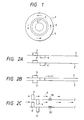
- Fig. 1 shows a magnetic recording medium and Figs. 2A ⁇ C show tracking pits and clock pits that are preformed along recording tracks formed on the recording surface of this magnetic recording medium.
- a magnetic recordina medium disk 1 is made of glass, a resin or aluminium, and a large number of tracking servo pits 3, 3', 4, 4' are periodically preformed on the recording surface along concentric or spiral tracks 2, 2' by etching or injection moulding as shown in Figs. 2 A ⁇ C
- These pits are appropriately preformed by removing the magnetic film by ion milling or reactive ion etching.
- At least a pair of pits 3, 4 (3', 4') that are preformed and distributed to the right and left with respect to the centre line of the tracks 2, 2' are used as servo marks.
- the tracking servo pits can be used commonly for the adjacent tracks 2 and 2'.
- the tracking servo pits may be preformed in a great width in such a manner as to overlap partially with one another in the advancing direction of the tracks, that is, in the circumferential direction, as shown in Fig. 2 C
- 2C represent clock pits that are disposed along the centre line of the tracks 2, 2' and these clock pits, too, are preformed by removing the magnetic film by ion milling-or reactive ion etching in the same way as the tracking servo pits.
- these preformed pits 3, 4, 35, 3', 4', 35' are preferably elongated thinly in a direction at right angles to the data recording direction (the track direction) as shown in Figs. 3A ⁇ C and their length d is preferably equal to the width D of the recording area 30 of the magnetic head (the magnetic gap represented by oblique lines).
- These preformed pits 3, 4, 35, 3', 4', 35' may be inclined with respect to the tracks 2, 2' as shown in Fig. 3D and the data, too, are recorded obliquely by the magnetic gap 30 of the magnetic head which is inclined with respect to the tracks. In this manner, cross-talk between the tracks 2, 2' can be eliminated and the track pitch can be further reduced.
- a magnetic recording thin film (a ferromagnetic film) 5 is formed on this medium disk 1 but it does not exist at the portions of the preformed pits 3, 3', 35, 4, 4', 35'. While the magnetic recording medium (magnetic film) 5 is being rotated, its entire surface is uniformly magnetized initially by the magnet. The direction 6 of magnetization is in agreement with the disk circumferential direction, that is, the data recording direction.
- Fig. 4 is a sectional view when the preformed pits 20 such as the servo pits 3, 3', 4, 4' or the clock pits 35, 35' are viewed in the disk circumferential direction, that is, in the data recording direction.
- Fig. 4A shows the state where the magnetic head 10 reads the preformed pit 20.
- reference numeral 5 represents the recording magnetic film formed on the substrate 1.
- This magnetic recording thin film (magnetic film) 5 is magnetized in one direction 6 by initial magnetization, and no leakage magnetic field exists at the place spaced apart from the preformed pits 20.
- positive and negative magnetic poles 7 and 8 are formed at both of their edges so that a leakage magnetic field occurs from both edges of the preformed pit portion 20.
- the preformed pits 20 (3, 3', 4, 4', 35, 35') are read magnetically when this leakage magnetic field is detected by the magnetic head 10 positioned on the magnetic recording medium.
- the magnetic head 10 which is positioned on the rotating magnetic disk recording medium floats with a delicate floating distance of less than ⁇ ms, for example.
- Figs. 4B ⁇ D show the magnetic film structure near the preformed pit 20.
- Fig. 4B shows an example where the substrate 1 of the pit portion 20 (3, 3', 4, 4', 35, 35') is flat and the magnetic film 5 does not exist at this portion.
- the N and S magnetic poles 7 and 8 are formed at both edges of the preformed pit 20 and therefore, the leakage magnetic field 9 occurs at both edges of the preformed pit 20.
- Fig. 4 C shows the case where substrate 1 at the portion of the preformed pit 20 is convex and no magnetic film 5 exists at this convex pit portion.
- Fig. 4D shows the case where the preformed pit 20 is concave and no magnetic film 5 exists at this concave pit portion, either.
- the depth of these preformed pits 20 is preferably substantially equal to the pit width in the data recording direction and, if the magnetic film 5 is 0.1 ⁇ m thick, for example, the depth of the preformed pit 20 is from 0.1 to 0.5 ⁇ m.
- the pit length of the preformed pit 20 in the data recording direction may be 0.5 ⁇ m and the pit width in the disk radial direction, from 1 to 20 ⁇ m. In any of the cases shown in Figs.
- the N and S magnetic poles 7, 8 are formed at both edges of the preformed pit 20 (the servo pits 3, 3', 4, 4' or the clock pits 35, 35') so that the leakage magnetic field 9 occurs at both edges of the preformed pit 20.
- These pits can be detected magnetically by detecting the magnetic flux 9 occurring at the edges of the preformed pit 20 by the magnetic head 10 .
- magnetic reading can be made by scanning such preformed pits 20 by the magnetic head 10 and detecting the magnetic flux 11 formed at the core 13 of the magnetic head 10 when the magnetic head 10 passes the preformed pits 20, by the magnetic coil 12.
- Fig. 5 shows the intensity of the magnetic flux passing through the magnetic coil 12 when the magnetic head 10 scans the preformed pit 20 in a direction at right angles to the data recording direction, that is, in the radial direction.
- This magnetic flux 11 provides a desirable output signal if the dimension D of the magnetic head 10 in the direction at right angles to the data recording direction is made to be substantially equal to the width d of the preformed pit 20 in the direction at right angles to the data recording direction.
- the magnetic flux 11 is symmetric with respect to the pit centre and thouqh the degree of track deviation can be known therefrom, the direction of the track deviation cannot be detected.
- the present embodiment uses preformed pits 3, 4 (3', 4') that are wobbled with respect to the track centre on the magnetic recording medium as tracking servo pits for detecting the degree and direction of the track deviation.
- the tracking signal representing the degree and direction of the track deviation can be obtained by sampling and detecting the read signals of the magnetic head 10 which are obtained when the magnetic head 10 passes over the preformed pits 3, 4 (3', 4') and determining the difference between them.
- tracking control In order to make control so that the position of the magnetic gap 30 of the magnetic head 10 is in conformity with the track centre, tracking control must be made by moving the position of the magnetic head 10 in the direction at right angles to the data recording direction (i.e. in the radial direction) by use of the detected tracking signals so as to always obtain the detection waveform.shown in Fia. 7B.
- Fig. 8 shows the case where both recording/reading of the data and detection of the tracking signal can be made by use of one magnetic head 10 .
- the concentric or spiral track 2 is divided into the servo area for detecting the tracking signal and the sync signal and the data area for recording/reading the data. A large number of these servo areas and data areas are disposed alternately and periodically along the track.
- the preformed pits in these servo areas and the recorded data in the data areas are detected by one magnetic head 10 on a time division basis.
- a pair of preformed pits 3, 4 described above which are wobbled with respect to the track centre on the magnetic recording medium are formed as the tracking servo marks for detecting the degree and direction of the track deviation, in each servo area.
- the clock pits represented by reference numerals 35 and 35' in Figs. 2C and 3 C may be disposed along the track centre line in each servo area. They may also be inclined with respect to the track as shown in Fig. 3D. Furthermore, track address pits may be preformed along the track centre line, whenever necessary. As described already, these preformed pits in each servo area have locally different magnetic characteristics from those of the recording magnetic film 5 and are formed by removing the magnetic film 5 by ion milling or reactive ion etching. They are read magnetically by detecting the leakage magnetic field generated from both edges of these preformed pits by the magnetic head 10 .
- the tracking signal can be obtained by sampling and detecting the leakage magnetic field occurring at the edges of the pair of wobbled preformed pits 3, 4 by the magnetic head 10 , as has already been explained in detail with reference to Figs. 6 and 7. While the magnetic head 10 is being subjected to the servo position control by the tracking signal thus obtained, desired data are recorded or read by the magnetic head 10 in the data areas between the servo areas along the centre line of the track.
- the magnetic head 10 is supported by a support mechanism (not shown in the drawing) connected to an actuator (not shown in the drawing) and can be moved in the direction at right angles to the data recording direction (e.g. in the radial direction of the magnetic disk) by driving this actuator.
- the magnetic head 10 when the actuator is driven on the basis of the detected tracking signal, the magnetic head 10 is subjected to the tracking control so that it always scans the centre of the track and the data can be accurately recorded or read along the track centre of the data areas by the magnetic head 10 which is subjected to the tracking control.
- the magnetic film 5 is a magnetic thin film for horizontal recording and the data recorded in the data area are recorded horizontally ( i.e. magnetized in a direction parallel to the magnetic film 5) by the magnetic head 10 .
- Figs. 9 and 10 show other examples of track patterns of the magnetic recording medium.
- the servo areas for detecting the tracking area and the data areas for recording the data are separated in the track and one magnetic coil detects the signals on the time division basis in the same way as in Fig. 8.
- the desired data are recorded and read by the magnetic head which is subjected to tracking control, into and from the data area between the servo areas along the track centre.
- a pair of circular pits 53, 54 are preformed in the wobbling arrangement with respect to the track centre, as the tracking servo marks in each servo area.
- Fig. 9 show other examples of track patterns of the magnetic recording medium.
- the servo areas for detecting the tracking area and the data areas for recording the data are separated in the track and one magnetic coil detects the signals on the time division basis in the same way as in Fig. 8.
- the desired data are recorded and read by the magnetic head which is subjected to tracking control, into and from the data area between the servo areas along the track centre
- a pit line 63 having a frequency f 1 is preformed at a position deviated slightly in a - (minus) direction from the track centre (on the inner circumferential side in the direction at right angles to the data recording direction, for example) in each servo area and another pit line 64 having a frequency f 2 is preformed at a position deviated in a + (plus) direction.
- the preformed pit lines 63, 63 are composed of circular pits. In order to improve the recording density in the track direction and S/N, however, it is more suitable to preform the pit lines 63, 64 with rectangular pits which are elongated in the direction at right angles to the data recording direction and have lengths substantially equal to the width of the recording area 30 of the magnetic head 10 .
- Fig. 11 shows the pit lines 72, 73 having different frequencies f 1 , f 2 that are preformed with rectangular pits. Since the pit lines having the frequencies f 1 , f 2 can be separately detected by frequency discrimination, they can be simultaneously preformed on both sides of the track centre as shown in Fig.
- the detection signal of the magnetic head 10 scanning along the track is separated into the component of the frequency f 1 and the component of the frequency f 2 by a frequency discriminator 65.
- Each frequency component is amplified by a differential amplifier 66 and the tracking signal can be obtained.
- the tracking signal is sent to the actuator for changing the position of the magnetic head in the radial direction.
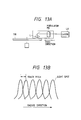
- Fig. 13 shows a recording apparatus of a photomask used in a production method.
- This recording apparatus is for recording patterns of data to be stored in advance on the magnetic recording medium 1 or patterns of the signals to be preformed, such as the ROM data which are stored in advance in the ROM area and can be read magnetically, and patterns of the signals to be preformed such as servo marks, clock pits, address pits, and the like, which are provided in a large number periodically along the track in the ROM area and/or the RAM area and can be read magnetically in the servo areas, onto a chromium photomask 130 by ultraviolet laser beam.
- the chromium photomask 130 is fixed to a spindle receptacle and is rotated.
- NA 0.93
- each preformed pit 20 constituting the ROM data, the tracking servo mark, the clock pit and the address pit is elongated in the disk radial direction and its size is 5 ⁇ m, for example. Then, a longitudinally elongated pit can not be formed by the circular spot of 0.4 ⁇ m.
- FIG. 13B is an explanatory view useful for explaining an example of the method of forming a longitudinally elongated pit.
- the optical system moves linearly in the disk radial direction while being placed on a moving table and it is advisable to control its moving speed so that the optical system moves by a distance smaller than the optical spot diameter such as a distance equivalent substantially to the radius of the optical spot while the photomask 130 rotates once. Then, the integration value of the quantity of the beam irradiated to the desired portion of the photomask 130 becomes a uniform rectangle as shown in Fig. 13 B.
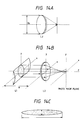
- Fig. 14 shows another method of forming the rectangular preformed pit. This embodiment improves the optical system in the recording apparatus of the photomask 130.
- a rectangular laser spot having a width of 0.5 ⁇ m and a length of 10 ⁇ m must be formed on the photomask 130 by the laser beam of the optical system.
- an elongated spot can be obtained by disposing a cylindrical lens L1 on the laser incident side of the objective lens L2 If the focal length of the cylindrical lens L1 is f x and f y in the x and y directions, respectively, f x is infinite whereas f y is definite and is 1 m, for example.
- the mask 130 on which the patterns consisting of the preformed pits 20 (tracking servo pits 3, 4, 3', 4', ...; 53, 54; 63, 64; 72, 73; address pits and clock pits 35, 35', ..., later-appearing ROM data pits 17, ...) are recorded, is developed by the recording apparatus of the photomask described above and, after etching is effected, the mask 130 having the patterns of the desired preformed pits 20 recorded thereon can be obtained.
- the magnetic recording medium is produced by use of this mask 130 in accordance with the processes of an embodiment of the present invention shown in Figs. 15 to 18.
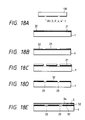
- Fig. 15 shows an example of a production method of the magnetic recording medium obtained by removing the magnetic thin film (magnetic film) 5 of each preformed pit 20.
- a neqative resist 22 is applied to an aluminium or glass disk substrate 1 and exposure is effected by bringing the mask 130 described above into close contact with this photoresist-coated disk substrate 1.
- the mask 130 is removed and development is then made.
- the photoresist 23 at portions other than the pit portions 20 is dissolved by development and remains only at the pit portions.
- the magnetic thin film 5 is formed by sputtering on the entire surface of the disk substrate 1 on which the resist 23 described above remains.
- the resist 23 on the disk is removed therefrom.
- the magnetic thin film 5 at the pit portions 20 is removed and the magnetic recording medium without the magnetic film 5 only at the pit portions 20 can thus be formed.
- the magnetic film 5 which is applied in a projecting form may be removed.
- the magnetic film at the pit portions where the magnetic film is applied in the projecting form can be eliminated.
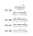
- Fig. 16 shows another example of a production method of the magnetic recording medium from which the magnetic film (magnetic recording film) 5 at each pit portion 20 is removed.
- the positive photoresist 21 is applied and then exposure is effected by bringing the mask 130 described above into close contact with the disk substrate 1 on which the magnetic film 5 and the photoresist 21 are thus formed.
- the mask 130 is removed and then development is effected. The resist at the pit portions 20 is dissolved by the development but the resist at other portions remains.
- Fig. 16 A after the magnetic thin film 5 is uniformly formed by sputtering on the aluminium or glass substrate 1, the positive photoresist 21 is applied and then exposure is effected by bringing the mask 130 described above into close contact with the disk substrate 1 on which the magnetic film 5 and the photoresist 21 are thus formed.
- the mask 130 is removed and then development is effected.
- the resist at the pit portions 20 is dissolved by the development but the resist at other portions remains.
- Fig. 17 shows an example of a production method of the magnetic medium whose preformed pits 20 are made of a non-ferromagnetic material.
- Fig. 17 the processes shown in Figs. 17A, B and D are the same as those shown in Figs. 16,A, B and D respectively.
- Fig. 17 C hydrogen, argon, nitrogen, boron, neon or dysprosium 23' is implanted to convert the magnetic film 5 at the preformed pit portions from the ferromagnetic material to the non-ferromagnetic material so as to obtain a magnetic recording medium of which only the preformed pit portions 20 are not ferromagnetic.
- the magnetic poles are formed on both edges of each preformed pit 20 because the magnetic film is ferromagnetic at portions other than at the pit portions.
- Fig. 19 shows in enlargement the portion of the preformed pits 20 in accordance with this production method.
- Fig. 18 shows an example of a production method of the magnetic recording medium not having a base film for each preformed pit 20.
- a Cr thin film 32 is formed by sputterinq on the aluminium or glass disk substrate 1 and the positive resist 21 is then applied. Exposure is effected by bringing the afore-mentioned mask 130 into close contact with the disk substrate 1 on which this Cr base film 32 and the photoresist 21 are formed.
- the mask 130 is removed and development is then effected. The resist 21 at the pit portions 20 is dissolved by the development but the resist 21 at other portions remains.
- Fig. 18 shows an example of a production method of the magnetic recording medium not having a base film for each preformed pit 20.
- the Cr thin film 32 at the pit portions 20 not having the resist 21 is removed by reactive ion etching, for example.
- the resist 21 at the unexposed portions on the disk is removed by an organic solvent, for example.
- the ferromagnetic film 5 such as CoNiZr and a protective film 34 such as C are uniformly formed by sputtering on the pattern of the Cr thin film 32. This production method can produce the magnetic recording medium without the Cr base film 32 only at the preformed pit portions 20.
- Fig. 20 shows in enlargement the portion of the preformed pit 20 in accordance with this production method.
- Fig. 20 A shows the case where the magnetic head 10 scans the preformed pit 20
- Fig. 20 B shows the magnetic film structure near the preformed pit 20.
- the structure of the magnetic film at portions other than the preformed pit portions 20 is formed by sputtering a 300 to 500 nm-thick Cr film 32 as the base film on the aluminium (Al) or glass substrate 1, then sputtering a 50 to 70 nm-thick ferromagnetic film 5 such as CoNiZr on the former and further sputtering the protective film 34 such as C.
- the Cr base film 32 is partially removed at each preformed pit portion 20, where only the ferromagnetic film (magnetic recording film) 5 and the protective film 34 are formed.
- the magnetic recording medium is initially magnetized uniformly by a magnet on its entire surface while it is being rotated.
- the direction 6 of magnetization is in conformity with the disk circumferential direction, that is, the data recording direction.
- the Cr base film 32 has the effect of improving saturated magnetization Ms of the ferromagnetic film 5. Since the Cr base film 32 does not exist at each preformed pit portion 20, saturated magnetization becomes small there. If the recording magnetic film 5 is magnetized unidirectionally 6 by initial magnetization, the leakage of the magnetic field does not occur at positions spaced apart from the preformed pits 20. However, since saturated magnetization is small at each preformed pit portion 20 such as the servo pits 3, 4, 3', 4', etc., positive and negative magnetic poles are formed at both edges 7, 8 of each preformed pit 20 and as a result, the leakage of the magnetic field 9 occurs from the edges of each preformed pit. Accordingly, the pits can be read magnetically by the magnetic head 10 in the same way as described already.
- the production method of the present invention can easily form a magnetic recording medium having preformed pits whose magnetic characteristics are locally different from those of the magnetic film and which can be detected magnetically. Moreover, since the mask 130 having the preformed pit patterns to be provided in advance on the magnetic recording medium can be used a large number of times, large quantities of magnetic recording media having the same pattern can be produced precisely.
- the production method shown in Figs. 15 to 18 can also form arbitrary patterns other than the preformed pits, and can preform, for example, linear ditches free from the magnetic thin film on the magnetic recording medium by forming in advance such linear ditches.
- pits for synchronization, address pits or pits for access can be likewise preformed as the servo pits besides the tracking pits.
- the protective film 34 has not been explained in the production methods shown in Figs. 15 to 17, the protective film 34 of C or the like is preferably formed on the recording magnetic film 5 in the production methods shown in Figs. 15 to 17 in the same way as in the production step shown in Fig. 18E.
- the data area between the servo areas assumes the case of the magnetic recording medium which can be freely recorded and erased by the magnetic head 10 .
- a disk having such a function is referred to as a "disk having the RAM function”.
- the form of a disk wherein the areas 40 having the RAM function and the ROM or read-only areas 39 exist in mixture as shown in Fig. 21 can be conceived.
- Such a structure provides the advantage that the read-only data and the rewritable data can be accessed simultaneously within a short period of time.
- the magnetic disk 1 has the magnetic film to and from which the data can be recorded and read magnetically, the second area (RAM area) 40 to and from which the user can record and read the data magnetically and the first area (ROM area) 39 in which magnetically readable data are preformed.
- the RAM area 40 is shown disposed on the outer peripheral side and the ROM area 39, on the inner peripheral side.
- the RAM area 40 is shown disposed on the outer peripheral side and the ROM area 39, on the inner peripheral side and at the same time, the ROM area 39 is divided by suitable angles and exists in mixture inside the RAM area 40.
- the concentric or spiral tracks are disposed in the RAM area 40 and in the ROM area 39, and the data are recorded and read and/or read only along the tracks.
- Fig. 23 shows the data recording tracks in the RAM area 40 described above.
- the data tracks 2, 2' consist of the combination of a large number of servo areas 15 disposed periodically along the track and the RAM data 16 recorded in the user data recording areas (data areas) between these servo areas 15.
- the preformed pits each having the different magnetic characteristics from those of the recording magnetic film and formed by etching and removing locally the magnetic film, as described above, are formed in each servo area 15 and the tracking signal is obtained by sampling and detecting magnetically the magnetic field occurring at the edges of the preformed pit inside the servo area 15 by the magnetic head 10 . While the magnetic head 10 is being subjected to the servo position control on the basis of the tracking signal thus obtained, the desired RAM data (e.g.
- the magnetic film is a magnetic thin film for horizontal recording and the RAM data 16 are horizontally recorded or read by the magnetic head 10 which is subjected to the tracking control.
- the tracking marks consisting of a pair of tracking servo pits distributed to the right and left with respect to the centre line of the tracks 2, 2' as explained with reference to Figs. 2, 3, 9 or the pit lines 63, 64,72, 73 distributed to the right and left with respect to the centre line and having different frequencies and/or phases as explained with reference to Figs. 10 and 11, are used as the preformed pits inside the servo area 15.
- the address pits and the clock pits 35, 35' are preformed, whenever necessary.
- Fig. 24 shows one example.
- Fig. 24 shows one example of the recording track inside the RAM area 40.
- a pair of wobbled servo pits 3, 4 which are wobbled with respect to the track centre are preformed as the tracking servo marks in each servo area 15.
- the pits represented by reference numeral 35 are preformed pits relating to the clock and access marks, which have the same magnetic film structure as the servo pits 3, 4 and are preformed on the substrate 1.
- Reference numeral 36 represents the groove formed between the tracks and these grooves are directed to reduce cross-talk between the tracks at the time of the data read-out operation. This groove 36, too, has the same structure as the servo pits 3, 4 and are preformed.
- Reference numeral 16 represents the data which are magnetically recorded by the magnetic head 10 .
- Fig. 25 shows the data read-only track inside the ROM area 39 described above.
- each data track 2, 2' consists of the combination of a large number of servo areas 15 disposed periodically along the track and the read-only ROM data (e.g. code data) 17 disposed between these servo areas 15.
- each of the servo area 15 and ROM data 17 is composed of the preformed pits formed by locally etching and removing the magnetic film and having the different magnetic characteristics from those of the recording magnetic film, for example, as described already.
- the tracking signal is obtained by sampling and detecting magnetically the magnetic field generated at the edges of the preformed pits in these servo areas 15 and while the magnetic head is being subjected to the servo position control on the basis of the tracking signal, the ROM data 17 between the servo areas 15 are read along the centre line of the tracks 2, 2'.
- the ROM data 17 are only read by the magnetic head but are not recorded by the magnetic head.
- Fig. 26 shows an example of the recording tracks in the ROM area 39.
- the preformed pits 3, 4, 35 in the servo area 15 and the grooves 36 between the tracks in the data area are the same as those shown in Fig. 24.
- the pits 17 in the data area are preformed by the same method as that for the preformed pits 3, 4, 35 in the servo area, in the ROM area 39.
- the pits in the servo area and the ROM data 17 in the data area are formed by locally etching and removing the recording film, for example.
- the tracking signal is obtained by magnetically sampling and detecting the magnetic field generated at the edges of each preformed pit in these servo areas and while the magnetic head is being subjected to the servo position control on the basis of the tracking signal, the ROM data 17 inside the data areas between the servo areas are read along the centre line of the track.
- This embodiment can economically duplicate and record the ROM data into the magnetic recording medium and moreover, since the ROM data and the RAM data exist in mixture, the embodiment can save the trouble of copying the software to the magnetic recording medium by use of a floppy because a software program or the like can in advance be formed as the ROM data in the magnetic recording medium when it is used in an apparatus such as a personal computer.
- the data can be recorded to and read from the second areas (RAM areas) or can be read out from the first areas (ROM areas) by magnetically detecting the flux distribution occurring at each preformed pit of the servo areas by the magnetic head and making the servo position control.
Abstract
Description
Accordingly, a tracking signal can be detected by the magnetic head alone with a high S/N, and moreover, the apparatus is compact in scale.
In this arrangement, the N and S magnetic poles 7 and 8 are formed at both edges of the preformed pit 20 and therefore, the leakage magnetic field 9 occurs at both edges of the preformed pit 20.
Fig. 4 C shows the case where substrate 1 at the portion of the preformed pit 20 is convex and no magnetic film 5 exists at this convex pit portion. Fig. 4D shows the case where the preformed pit 20 is concave and no magnetic film 5 exists at this concave pit portion, either. The depth of these preformed pits 20 (3, 3', 4, 4', 35, 35') is preferably substantially equal to the pit width in the data recording direction and, if the magnetic film 5 is 0.1 µm thick, for example, the depth of the preformed pit 20 is from 0.1 to 0.5µm. The pit length of the preformed pit 20 in the data recording direction may be 0.5 µm and the pit width in the disk radial direction, from 1 to 20 µm. In any of the cases shown in Figs. 4B ∼ D the N and S magnetic poles 7, 8 are formed at both edges of the preformed pit 20 (the servo pits 3, 3', 4, 4' or the clock pits 35, 35') so that the leakage magnetic field 9 occurs at both edges of the preformed pit 20. These pits can be detected magnetically by detecting the magnetic flux 9 occurring at the edges of the preformed pit 20 by the magnetic head 10. In other words, magnetic reading can be made by scanning such preformed pits 20 by the magnetic head 10 and detecting the magnetic flux 11 formed at the core 13 of the magnetic head 10 when the magnetic head 10 passes the preformed pits 20, by the magnetic coil 12.
When the magnetic head passes along the one-dot-chain line A, the magnetic head passes on the pit 3 so that the signal detected by the magnetic head is great in the case of the signal from the pit 3 but is small in the case of the signal from the pit 4. Accordingly, the detection signal shown in Fig. 7A can be obtained. Fig. 7B shows the detection waveform in the case where the magnetic head passes along the solid line B (track centre) and Fig. 7C shows the detection waveform in the case where the magnetic head passes along the two-dot-chain line C in Fig. 6. Therefore, the tracking signal representing the degree and direction of the track deviation can be obtained by sampling and detecting the read signals of the magnetic head 10 which are obtained when the magnetic head 10 passes over the preformed pits 3, 4 (3', 4') and determining the difference between them. In order to make control so that the position of the magnetic gap 30 of the magnetic head 10 is in conformity with the track centre, tracking control must be made by moving the position of the magnetic head 10 in the direction at right angles to the data recording direction (i.e. in the radial direction) by use of the detected tracking signals so as to always obtain the detection waveform.shown in Fia. 7B.
The concentric or spiral track 2 is divided into the servo area for detecting the tracking signal and the sync signal and the data area for recording/reading the data. A large number of these servo areas and data areas are disposed alternately and periodically along the track. The preformed pits in these servo areas and the recorded data in the data areas are detected by one magnetic head 10 on a time division basis. A pair of preformed pits 3, 4 described above which are wobbled with respect to the track centre on the magnetic recording medium are formed as the tracking servo marks for detecting the degree and direction of the track deviation, in each servo area. Incidentally, the clock pits represented by reference numerals 35 and 35' in Figs. 2C and 3 C may be disposed along the track centre line in each servo area. They may also be inclined with respect to the track as shown in Fig. 3D.
Furthermore, track address pits may be preformed along the track centre line, whenever necessary.
As described already, these preformed pits in each servo area have locally different magnetic characteristics from those of the recording magnetic film 5 and are formed by removing the magnetic film 5 by ion milling or reactive ion etching. They are read magnetically by detecting the leakage magnetic field generated from both edges of these preformed pits by the magnetic head 10. The tracking signal can be obtained by sampling and detecting the leakage magnetic field occurring at the edges of the pair of wobbled preformed pits 3, 4 by the magnetic head 10, as has already been explained in detail with reference to Figs. 6 and 7. While the magnetic head 10 is being subjected to the servo position control by the tracking signal thus obtained, desired data are recorded or read by the magnetic head 10 in the data areas between the servo areas along the centre line of the track. The magnetic head 10 is supported by a support mechanism (not shown in the drawing) connected to an actuator (not shown in the drawing) and can be moved in the direction at right angles to the data recording direction (e.g. in the radial direction of the magnetic disk) by driving this actuator. Accordingly, when the actuator is driven on the basis of the detected tracking signal, the magnetic head 10 is subjected to the tracking control so that it always scans the centre of the track and the data can be accurately recorded or read along the track centre of the data areas by the magnetic head 10 which is subjected to the tracking control. Incidentally, if the data area is elongated, it is advisable to hold the detected tracking signal from the wobbled pits of the servo areas during the data area period. In this embodiment the magnetic film 5 is a magnetic thin film for horizontal recording and the data recorded in the data area are recorded horizontally ( i.e. magnetized in a direction parallel to the magnetic film 5) by the magnetic head 10.
In Fig. 13 A, the chromium photomask 130 is fixed to a spindle receptacle and is rotated. A laser beam such as argon laser (w = 0.45 µm) LA is intensity-modulated by an optical modulator MD in accordance with the signal to be preformed and, when it is condensed by a lens system L having high NA (e.g. NA = 0.93), it forms a circular spot having a diameter of about 0.4 µm on the rotary mask 130. It will be assumed here that each preformed pit 20 constituting the ROM data, the tracking servo mark, the clock pit and the address pit is elongated in the disk radial direction and its size is 5 µm, for example. Then, a longitudinally elongated pit can not be formed by the circular spot of 0.4 µm.
Fig. 13B is an explanatory view useful for explaining an example of the method of forming a longitudinally elongated pit. In Fig. 13A, the optical system moves linearly in the disk radial direction while being placed on a moving table and it is advisable to control its moving speed so that the optical system moves by a distance smaller than the optical spot diameter such as a distance equivalent substantially to the radius of the optical spot while the photomask 130 rotates once. Then, the integration value of the quantity of the beam irradiated to the desired portion of the photomask 130 becomes a uniform rectangle as shown in Fig. 13 B. In order to form a longitudinally elongated preformed pit of 5 µm by the optical spot diameter of 0.4 µm, for example, the moving distance of the optical system is 0.2 µm/revolution and intensity modulation of the beam may be effected at desired timing while the photomask 130 rotates 25 turns, i.e. 5/0.2 = 25, in accordance with the signal to be preformed.
Therefore, the following equation is established from the optical system shown in Fig.14 B
In this manner, it becomes possible to form a rectangular laser spot such as shown in Fig. 14 C, which is 0.5 µm wide and 5 to 10 µm long by disposing the cylindrical lens L1 having a focal length fy of 50cm to 10m in front of the objective lens L2.
This groove 36, too, has the same structure as the servo pits 3, 4 and are preformed. Reference numeral 16 represents the data which are magnetically recorded by the magnetic head 10.
Claims (11)
- A magnetic recording medium having a magnetic film (5) for magnetically recording and reading data (16), comprising first areas (39) containing magnetically readable pre-recorded data (17) composed of preformed pits whose magnetic characteristics are locally different from those of said magnetic film and to be magnetically detected by magnetic flux distribution occurring at the edges of said pits; and second areas (40) for magnetically recording and reading data (16).
- The recording medium of claim 1, wherein said first and second areas (39, 40) co-exist in mixture and are defined at least partly by radial division of a disk-shaped recording medium.
- The recording medium of claim 1 or 2, wherein said pre-recorded data (17) are recorded in said first areas (39) by removing partially said magnetic film (5).
- The recording medium of any of claims 1 to 3, wherein a large number of magnetically readable servo pits (3, 4) recorded by partial removal of said magnetic film (5) are periodically provided along a track (2, 2') and said pre-recorded data (17) are provided between said servo pits (3, 4).
- The recording medium of any of claims 1 to 3, wherein a large number of magnetically readable servo pits (3, 4) recorded by partial removal of said magnetic film (5) are periodically provided along a track (2, 2') and the portions between said servo pits (3, 4) are used as second areas (40) for magnetically recording and reading data (16).
- A method of producing the magnetic recording medium (5) of any preceding claim, using a mask (130) having a pattern of pre-recorded pits (20) comprising:exposing a resist (22) disposed on a magnetic film, whereby said film is for magnetically recording and reading data (5) through said mask (130);removing the exposed part of said resist (22) corresponding to said pattern; andmodifying the magnetic characteristics of the portion of said magnetic film (5) corresponding to said pattern using the remaining part of said resist (22) as a mask to thereby preform magnetically readable pits (20) on first areas (39) and to leave second areas (40) for magnetically recording and reading data.
- The method of claim 6, wherein said pits (20) are pre-formed by removing the portions of said magnetic film (5) corresponding to said pattern.
- The method of claim 6 or 7, wherein said pits (20) are preformed by converting the portions of said magnetic film (5) corresponding to said pattern to a non-ferromagnetic state.
- The method of claim 6 or 7, wherein said pits (20) are preformed by local removal of a base film (32) below said magnetic film (5) corresponding to said pattern.
- A magnetic recording apparatus including a magnetic head (10) for detecting a tracking signal by sensing the magnetic field occurring at each of said preformed pits (20) formed on the magnetic recording medium of any of claims 1 to 5, and for magnetically recording data while controlling the recording position of said magnetic head (10) by said tracking signal.
- The recording apparatus of claim 10, wherein the length of each of said preformed pits (20) in a direction transverse to the data recording direction is substantially equal to the width of the recording portion of said magnetic head.
Applications Claiming Priority (15)
| Application Number | Priority Date | Filing Date | Title |
|---|---|---|---|
| JP2736/89 | 1989-01-11 | ||
| JP273689 | 1989-01-11 | ||
| JP17633/89 | 1989-01-30 | ||
| JP1763389 | 1989-01-30 | ||
| JP3103489 | 1989-02-13 | ||
| JP31034/89 | 1989-02-13 | ||
| JP38220/89 | 1989-02-20 | ||
| JP3822089A JPH02218016A (en) | 1989-02-20 | 1989-02-20 | Magnetic recording medium and magnetic recording device |
| JP6096789 | 1989-03-15 | ||
| JP60967/89 | 1989-03-15 | ||
| JP10162389 | 1989-04-24 | ||
| JP101623/89 | 1989-04-24 | ||
| JP15457089 | 1989-06-19 | ||
| JP154570/89 | 1989-06-19 | ||
| EP90100547A EP0378222B1 (en) | 1989-01-11 | 1990-01-11 | Magnetic recording medium and method of magnetically recording and reading data |
Related Parent Applications (1)
| Application Number | Title | Priority Date | Filing Date |
|---|---|---|---|
| EP90100547.0 Division | 1990-01-11 |
Publications (2)
| Publication Number | Publication Date |
|---|---|
| EP0657884A1 EP0657884A1 (en) | 1995-06-14 |
| EP0657884B1 true EP0657884B1 (en) | 1998-09-02 |
Family
ID=27563196
Family Applications (2)
| Application Number | Title | Priority Date | Filing Date |
|---|---|---|---|
| EP95101862A Expired - Lifetime EP0657884B1 (en) | 1989-01-11 | 1990-01-11 | Magnetic recording medium, method of producing it, and magnetic recording apparatus using it |
| EP90100547A Expired - Lifetime EP0378222B1 (en) | 1989-01-11 | 1990-01-11 | Magnetic recording medium and method of magnetically recording and reading data |
Family Applications After (1)
| Application Number | Title | Priority Date | Filing Date |
|---|---|---|---|
| EP90100547A Expired - Lifetime EP0378222B1 (en) | 1989-01-11 | 1990-01-11 | Magnetic recording medium and method of magnetically recording and reading data |
Country Status (3)
| Country | Link |
|---|---|
| US (1) | US5296995A (en) |
| EP (2) | EP0657884B1 (en) |
| DE (2) | DE69032626T2 (en) |
Families Citing this family (40)
| Publication number | Priority date | Publication date | Assignee | Title |
|---|---|---|---|---|
| US5568331A (en) * | 1989-10-27 | 1996-10-22 | Hitachi, Ltd. | Method of head positioning and magnetic recording disk drive using the same |
| US5768075A (en) * | 1991-12-17 | 1998-06-16 | Baradun R&D Ltd. | Disk medium w/magnetically filled features aligned in rows and columns |
| JP3254743B2 (en) * | 1992-08-17 | 2002-02-12 | ソニー株式会社 | Writing method of positioning signal |
| JPH06111502A (en) * | 1992-09-30 | 1994-04-22 | Sony Corp | Magnetic disk device |
| JP3344495B2 (en) * | 1993-03-04 | 2002-11-11 | ソニー株式会社 | Magnetic disk drive |
| US5430594A (en) * | 1993-05-10 | 1995-07-04 | Hitachi Maxell, Ltd. | Magnetic recording medium |
| US5583712A (en) * | 1993-06-24 | 1996-12-10 | Maxtor Corporation | Magnetic recording system having spiral tracks |
| US5993937A (en) * | 1993-11-30 | 1999-11-30 | Matsushita Electric Industrial Co., Ltd. | Magneto-optic recording medium and method of fabricating the same |
| US5585989A (en) * | 1993-11-30 | 1996-12-17 | Sony Corporation | Magnetic disc substrate and a magnetic disc using the same |
| US5537282A (en) * | 1994-07-15 | 1996-07-16 | Treves; David | Data storage disk having improved tracking capability |
| US6146740A (en) * | 1994-11-28 | 2000-11-14 | Matsushita Electric Industrial Co., Ltd. | Magnetic recording medium and method of fabricating the same |
| JPH08185676A (en) * | 1994-12-28 | 1996-07-16 | Sony Corp | Magnetic disk and disk device |
| US5576532A (en) * | 1995-01-03 | 1996-11-19 | Xerox Corporation | Interleaved and interlaced sync codes and address codes for self-clocking glyph codes |
| JPH08249602A (en) * | 1995-03-06 | 1996-09-27 | Mitsubishi Electric Corp | Magnetic storing/reproducing method and magnetic reproducing device used for it, magnetic storing medium, and its manufacturing method |
| JPH08300858A (en) | 1995-05-08 | 1996-11-19 | Dainippon Printing Co Ltd | Data recording medium |
| JPH09167308A (en) * | 1995-12-19 | 1997-06-24 | Canon Electron Inc | Magnetic reproducing method, magnetic detecting element, magnetic detector and magnetic recording medium |
| US6104579A (en) * | 1996-04-11 | 2000-08-15 | Sony Corporation | Magnetic disk head having data zone and control signal zones which generate different lifts when flown over by a head slider |
| KR19990044187A (en) * | 1996-06-26 | 1999-06-25 | 이데이 노부유끼 | Magnetic disk units, magnetic disks and disk cartridges |
| TW342495B (en) | 1996-07-22 | 1998-10-11 | Matsushita Electric Ind Co Ltd | Master information carrier, method of producing the same, and method for recording master information signal on magnetic recording medium |
| JP3384728B2 (en) * | 1997-11-12 | 2003-03-10 | 松下電器産業株式会社 | Method of manufacturing magnetic recording and reproducing apparatus and magnetic recording and reproducing apparatus |
| JP3329259B2 (en) | 1998-03-20 | 2002-09-30 | 松下電器産業株式会社 | Master information carrier and method of manufacturing magnetic recording medium |
| JP3361740B2 (en) | 1998-03-23 | 2003-01-07 | 松下電器産業株式会社 | Master information magnetic recording device and method of manufacturing magnetic recording medium |
| JP3639943B2 (en) * | 1998-04-22 | 2005-04-20 | 富士通株式会社 | Magnetic recording medium and magnetic head device |
| US6549360B1 (en) * | 1998-05-19 | 2003-04-15 | Seagate Technology Llc | Magnetic recording medium with laser-formed servo-marks |
| JP3344651B2 (en) | 1998-10-29 | 2002-11-11 | 松下電器産業株式会社 | Method of manufacturing magnetic recording medium using master information carrier |
| DE10084256T1 (en) | 1999-02-22 | 2002-01-31 | Seagate Technology Llc | Buried servo-patterned media |
| DE10085174T1 (en) * | 1999-11-12 | 2002-11-07 | Seagate Technology Llc | Magnetic media sampling using heat-induced phase transition |
| US6781785B2 (en) * | 1999-11-29 | 2004-08-24 | Jpmorgan Chase Bank | Method and system for utilizing circular marks in position error signal patterns |
| US6510015B2 (en) * | 1999-12-10 | 2003-01-21 | Seagate Technology Llc | Magnetic disc having physical servo patterns with a magnetic carrier, and method of making and using the same |
| WO2001065547A1 (en) * | 2000-03-01 | 2001-09-07 | Hitachi, Ltd. | Method and device for information recording/reproducing and information recording medium |
| JP3767470B2 (en) * | 2001-11-30 | 2006-04-19 | ブラザー工業株式会社 | Ink jet head and manufacturing method thereof |
| JP2006228348A (en) * | 2005-02-18 | 2006-08-31 | Sony Corp | Information writing device and method, magnetic disk manufacturing device and method, and magnetic disk |
| US7333289B2 (en) * | 2005-03-22 | 2008-02-19 | Tdk Corporation | Magnetic recording and reproducing apparatus, method of controlling the same, magnetic recording medium, and stamper for manufacturing magnetic recording medium |
| JP2008027524A (en) * | 2006-07-21 | 2008-02-07 | Hitachi Global Storage Technologies Netherlands Bv | Method for writing pattern on magnetic disk and device therefor |
| US7612961B2 (en) * | 2007-10-12 | 2009-11-03 | Hitachi Global Storage Technologies Netherlands B.V. | Magnetic recording disk and disk drive with patterned phase-type servo fields for read/write head positioning |
| US20090201722A1 (en) * | 2008-02-12 | 2009-08-13 | Kamesh Giridhar | Method including magnetic domain patterning using plasma ion implantation for mram fabrication |
| US8535766B2 (en) | 2008-10-22 | 2013-09-17 | Applied Materials, Inc. | Patterning of magnetic thin film using energized ions |
| US20090199768A1 (en) * | 2008-02-12 | 2009-08-13 | Steven Verhaverbeke | Magnetic domain patterning using plasma ion implantation |
| US8551578B2 (en) * | 2008-02-12 | 2013-10-08 | Applied Materials, Inc. | Patterning of magnetic thin film using energized ions and thermal excitation |
| US9111565B2 (en) * | 2009-01-16 | 2015-08-18 | Seagate Technology Llc | Data storage device with both bit patterned and continuous media |
Family Cites Families (14)
| Publication number | Priority date | Publication date | Assignee | Title |
|---|---|---|---|---|
| US3034111A (en) * | 1958-11-24 | 1962-05-08 | Ibm | Data storage system |
| US3593331A (en) * | 1969-01-31 | 1971-07-13 | Ncr Co | Magnetic disc calibration track with diminishing apertures |
| US3753252A (en) * | 1971-06-28 | 1973-08-14 | Ibm | Disk pack assembly and method of making |
| US4188646A (en) * | 1978-05-30 | 1980-02-12 | Sperry Rand Corporation | Sectorized data path following servo system |
| JPS58111130A (en) * | 1981-12-24 | 1983-07-02 | Omron Tateisi Electronics Co | Magnetic recording medium |
| EP0120990B1 (en) * | 1983-03-31 | 1989-05-31 | International Business Machines Corporation | Read-only magnetic recording media and process of making the same |
| US4746580A (en) * | 1983-03-31 | 1988-05-24 | International Business Machines Corporation | Read-only magnetic recording media |
| JPS62139179A (en) * | 1985-12-11 | 1987-06-22 | Csk Corp | Synchronous control system |
| JPS6410463A (en) * | 1987-07-01 | 1989-01-13 | Sony Corp | Magnetic disk |
| US4912487A (en) * | 1988-03-25 | 1990-03-27 | Texas Instruments Incorporated | Laser scanner using focusing acousto-optic device |
| US4935278A (en) * | 1988-04-28 | 1990-06-19 | International Business Machines Corporation | Thin film magnetic recording disk and fabrication process |
| US4912585A (en) * | 1988-04-28 | 1990-03-27 | International Business Machines Corporation | Discrete track thin film magnetic recording disk with embedded servo information |
| US4961123A (en) * | 1988-06-03 | 1990-10-02 | Insite Peripherals | Magnetic information media storage with optical servo tracks |
| US4935835A (en) * | 1988-11-10 | 1990-06-19 | Insite Peripherals, Inc. | Magnetic media containing reference feature and methods for referencing magnetic head position to the reference feature |
-
1990
- 1990-01-11 DE DE69032626T patent/DE69032626T2/en not_active Expired - Fee Related
- 1990-01-11 EP EP95101862A patent/EP0657884B1/en not_active Expired - Lifetime
- 1990-01-11 DE DE69021741T patent/DE69021741T2/en not_active Expired - Fee Related
- 1990-01-11 EP EP90100547A patent/EP0378222B1/en not_active Expired - Lifetime
-
1993
- 1993-01-04 US US08/000,549 patent/US5296995A/en not_active Expired - Lifetime
Also Published As
| Publication number | Publication date |
|---|---|
| DE69021741T2 (en) | 1996-04-18 |
| DE69032626T2 (en) | 1999-05-20 |
| DE69021741D1 (en) | 1995-09-28 |
| EP0378222A1 (en) | 1990-07-18 |
| DE69032626D1 (en) | 1998-10-08 |
| EP0378222B1 (en) | 1995-08-23 |
| US5296995A (en) | 1994-03-22 |
| EP0657884A1 (en) | 1995-06-14 |
Similar Documents
| Publication | Publication Date | Title |
|---|---|---|
| EP0657884B1 (en) | Magnetic recording medium, method of producing it, and magnetic recording apparatus using it | |
| US4672600A (en) | Optical disc having protective cover | |
| US5402411A (en) | Constant amplitude of tracking error signals generated from a head guide track and a performed track | |
| EP0656625A1 (en) | Optical disk and method for reproducing information recorded on the same | |
| US20050281177A1 (en) | High track density super resolution mo-rom medium | |
| EP0896325B1 (en) | High density optical disk, apparatus for reproducing optical disk and method for producing optical disk master | |
| US5892752A (en) | Optical recording medium and reproducing method and apparatus having offset preformat data | |
| EP0306324B1 (en) | An optical memory system | |
| EP0884722B1 (en) | Optical recording media | |
| US6800348B2 (en) | Optical recording medium | |
| JP2644840B2 (en) | optical disk | |
| US5432047A (en) | Patterning process for bipolar optical storage medium | |
| JP4024047B2 (en) | Optical recording medium and master for manufacturing optical recording medium | |
| EP0982716B1 (en) | Optical recording medium and master to produce it | |
| JP2816213B2 (en) | Magnetic recording / reproducing method of information | |
| EP0142927A2 (en) | Optical disc | |
| JPH08241512A (en) | Magnetic recording medium | |
| JP2806347B2 (en) | Magnetic disk drive | |
| JPH0765302A (en) | Magnetic recording medium and its production | |
| JPH09185820A (en) | Magnetic recording medium, its manufacture, and magnetic recorder | |
| JPH10188378A (en) | Magneto-optical recording medium and its recording and reproducing method | |
| JPH04184729A (en) | Optical recording medium and its manufacture | |
| JPH0765358A (en) | Magnetic recording medium and magnetic recorder | |
| JPH0765339A (en) | Magnetic recording medium and magnetic recorder | |
| JPH0765340A (en) | Magnetic recording medium and magnetic recording device |
Legal Events
| Date | Code | Title | Description |
|---|---|---|---|
| PUAI | Public reference made under article 153(3) epc to a published international application that has entered the european phase |
Free format text: ORIGINAL CODE: 0009012 |
|
| 17P | Request for examination filed |
Effective date: 19950228 |
|
| AC | Divisional application: reference to earlier application |
Ref document number: 378222 Country of ref document: EP |
|
| AK | Designated contracting states |
Kind code of ref document: A1 Designated state(s): DE FR GB |
|
| 17Q | First examination report despatched |
Effective date: 19960904 |
|
| GRAG | Despatch of communication of intention to grant |
Free format text: ORIGINAL CODE: EPIDOS AGRA |
|
| GRAG | Despatch of communication of intention to grant |
Free format text: ORIGINAL CODE: EPIDOS AGRA |
|
| GRAH | Despatch of communication of intention to grant a patent |
Free format text: ORIGINAL CODE: EPIDOS IGRA |
|
| GRAH | Despatch of communication of intention to grant a patent |
Free format text: ORIGINAL CODE: EPIDOS IGRA |
|
| GRAA | (expected) grant |
Free format text: ORIGINAL CODE: 0009210 |
|
| AC | Divisional application: reference to earlier application |
Ref document number: 378222 Country of ref document: EP |
|
| AK | Designated contracting states |
Kind code of ref document: B1 Designated state(s): DE FR GB |
|
| RIN1 | Information on inventor provided before grant (corrected) |
Inventor name: ITO, MASARU Inventor name: KINSTAETTER, KLAUS Inventor name: MIYAMOTO, HARUKAZU Inventor name: KATO, KEIZO Inventor name: TERASAWA, TSUNEO Inventor name: FUKKE, HAJIME Inventor name: KATAOKA, KEIJI Inventor name: YONEZAWA, SEIJI |
|
| REF | Corresponds to: |
Ref document number: 69032626 Country of ref document: DE Date of ref document: 19981008 |
|
| ET | Fr: translation filed | ||
| PLBE | No opposition filed within time limit |
Free format text: ORIGINAL CODE: 0009261 |
|
| STAA | Information on the status of an ep patent application or granted ep patent |
Free format text: STATUS: NO OPPOSITION FILED WITHIN TIME LIMIT |
|
| 26N | No opposition filed | ||
| REG | Reference to a national code |
Ref country code: GB Ref legal event code: IF02 |
|
| PGFP | Annual fee paid to national office [announced via postgrant information from national office to epo] |
Ref country code: GB Payment date: 20070108 Year of fee payment: 18 |
|
| PGFP | Annual fee paid to national office [announced via postgrant information from national office to epo] |
Ref country code: DE Payment date: 20070305 Year of fee payment: 18 |
|
| PGFP | Annual fee paid to national office [announced via postgrant information from national office to epo] |
Ref country code: FR Payment date: 20061220 Year of fee payment: 18 |
|
| GBPC | Gb: european patent ceased through non-payment of renewal fee |
Effective date: 20080111 |
|
| PG25 | Lapsed in a contracting state [announced via postgrant information from national office to epo] |
Ref country code: DE Free format text: LAPSE BECAUSE OF NON-PAYMENT OF DUE FEES Effective date: 20080801 |
|
| REG | Reference to a national code |
Ref country code: FR Ref legal event code: ST Effective date: 20081029 |
|
| PG25 | Lapsed in a contracting state [announced via postgrant information from national office to epo] |
Ref country code: GB Free format text: LAPSE BECAUSE OF NON-PAYMENT OF DUE FEES Effective date: 20080111 |
|
| PG25 | Lapsed in a contracting state [announced via postgrant information from national office to epo] |
Ref country code: FR Free format text: LAPSE BECAUSE OF NON-PAYMENT OF DUE FEES Effective date: 20080131 |