EP0657612A1 - Modular system for the formation of glass-enclosed closures - Google Patents
Modular system for the formation of glass-enclosed closures Download PDFInfo
- Publication number
- EP0657612A1 EP0657612A1 EP94201879A EP94201879A EP0657612A1 EP 0657612 A1 EP0657612 A1 EP 0657612A1 EP 94201879 A EP94201879 A EP 94201879A EP 94201879 A EP94201879 A EP 94201879A EP 0657612 A1 EP0657612 A1 EP 0657612A1
- Authority
- EP
- European Patent Office
- Prior art keywords
- bodies
- formation
- glass
- closures
- enclosed
- Prior art date
- Legal status (The legal status is an assumption and is not a legal conclusion. Google has not performed a legal analysis and makes no representation as to the accuracy of the status listed.)
- Withdrawn
Links
Images


Classifications
-
- E—FIXED CONSTRUCTIONS
- E06—DOORS, WINDOWS, SHUTTERS, OR ROLLER BLINDS IN GENERAL; LADDERS
- E06B—FIXED OR MOVABLE CLOSURES FOR OPENINGS IN BUILDINGS, VEHICLES, FENCES OR LIKE ENCLOSURES IN GENERAL, e.g. DOORS, WINDOWS, BLINDS, GATES
- E06B3/00—Window sashes, door leaves, or like elements for closing wall or like openings; Layout of fixed or moving closures, e.g. windows in wall or like openings; Features of rigidly-mounted outer frames relating to the mounting of wing frames
- E06B3/04—Wing frames not characterised by the manner of movement
- E06B3/263—Frames with special provision for insulation
- E06B3/26341—Frames with special provision for insulation comprising only one metal frame member combined with an insulating frame member
-
- E—FIXED CONSTRUCTIONS
- E06—DOORS, WINDOWS, SHUTTERS, OR ROLLER BLINDS IN GENERAL; LADDERS
- E06B—FIXED OR MOVABLE CLOSURES FOR OPENINGS IN BUILDINGS, VEHICLES, FENCES OR LIKE ENCLOSURES IN GENERAL, e.g. DOORS, WINDOWS, BLINDS, GATES
- E06B3/00—Window sashes, door leaves, or like elements for closing wall or like openings; Layout of fixed or moving closures, e.g. windows in wall or like openings; Features of rigidly-mounted outer frames relating to the mounting of wing frames
- E06B3/04—Wing frames not characterised by the manner of movement
- E06B3/263—Frames with special provision for insulation
- E06B3/26301—Frames with special provision for insulation with prefabricated insulating strips between two metal section members
- E06B3/26305—Connection details
- E06B2003/26312—Snap connections
-
- E—FIXED CONSTRUCTIONS
- E06—DOORS, WINDOWS, SHUTTERS, OR ROLLER BLINDS IN GENERAL; LADDERS
- E06B—FIXED OR MOVABLE CLOSURES FOR OPENINGS IN BUILDINGS, VEHICLES, FENCES OR LIKE ENCLOSURES IN GENERAL, e.g. DOORS, WINDOWS, BLINDS, GATES
- E06B3/00—Window sashes, door leaves, or like elements for closing wall or like openings; Layout of fixed or moving closures, e.g. windows in wall or like openings; Features of rigidly-mounted outer frames relating to the mounting of wing frames
- E06B3/04—Wing frames not characterised by the manner of movement
- E06B3/263—Frames with special provision for insulation
- E06B2003/26349—Details of insulating strips
- E06B2003/2635—Specific form characteristics
- E06B2003/26352—Specific form characteristics hollow
-
- E—FIXED CONSTRUCTIONS
- E06—DOORS, WINDOWS, SHUTTERS, OR ROLLER BLINDS IN GENERAL; LADDERS
- E06B—FIXED OR MOVABLE CLOSURES FOR OPENINGS IN BUILDINGS, VEHICLES, FENCES OR LIKE ENCLOSURES IN GENERAL, e.g. DOORS, WINDOWS, BLINDS, GATES
- E06B3/00—Window sashes, door leaves, or like elements for closing wall or like openings; Layout of fixed or moving closures, e.g. windows in wall or like openings; Features of rigidly-mounted outer frames relating to the mounting of wing frames
- E06B3/04—Wing frames not characterised by the manner of movement
- E06B3/263—Frames with special provision for insulation
- E06B2003/26349—Details of insulating strips
- E06B2003/26369—Specific material characteristics
- E06B2003/26374—Specific material characteristics with parts of differing nature
-
- E—FIXED CONSTRUCTIONS
- E06—DOORS, WINDOWS, SHUTTERS, OR ROLLER BLINDS IN GENERAL; LADDERS
- E06B—FIXED OR MOVABLE CLOSURES FOR OPENINGS IN BUILDINGS, VEHICLES, FENCES OR LIKE ENCLOSURES IN GENERAL, e.g. DOORS, WINDOWS, BLINDS, GATES
- E06B3/00—Window sashes, door leaves, or like elements for closing wall or like openings; Layout of fixed or moving closures, e.g. windows in wall or like openings; Features of rigidly-mounted outer frames relating to the mounting of wing frames
- E06B3/04—Wing frames not characterised by the manner of movement
- E06B3/263—Frames with special provision for insulation
- E06B2003/26349—Details of insulating strips
- E06B2003/26387—Performing extra functions
- E06B2003/26389—Holding sealing strips or forming sealing abutments
-
- E—FIXED CONSTRUCTIONS
- E06—DOORS, WINDOWS, SHUTTERS, OR ROLLER BLINDS IN GENERAL; LADDERS
- E06B—FIXED OR MOVABLE CLOSURES FOR OPENINGS IN BUILDINGS, VEHICLES, FENCES OR LIKE ENCLOSURES IN GENERAL, e.g. DOORS, WINDOWS, BLINDS, GATES
- E06B3/00—Window sashes, door leaves, or like elements for closing wall or like openings; Layout of fixed or moving closures, e.g. windows in wall or like openings; Features of rigidly-mounted outer frames relating to the mounting of wing frames
- E06B3/04—Wing frames not characterised by the manner of movement
- E06B3/263—Frames with special provision for insulation
- E06B2003/26396—Frames with special provision for insulation specially adapted for sheet metal frames
-
- E—FIXED CONSTRUCTIONS
- E06—DOORS, WINDOWS, SHUTTERS, OR ROLLER BLINDS IN GENERAL; LADDERS
- E06B—FIXED OR MOVABLE CLOSURES FOR OPENINGS IN BUILDINGS, VEHICLES, FENCES OR LIKE ENCLOSURES IN GENERAL, e.g. DOORS, WINDOWS, BLINDS, GATES
- E06B3/00—Window sashes, door leaves, or like elements for closing wall or like openings; Layout of fixed or moving closures, e.g. windows in wall or like openings; Features of rigidly-mounted outer frames relating to the mounting of wing frames
- E06B3/32—Arrangements of wings characterised by the manner of movement; Arrangements of movable wings in openings; Features of wings or frames relating solely to the manner of movement of the wing
- E06B3/34—Arrangements of wings characterised by the manner of movement; Arrangements of movable wings in openings; Features of wings or frames relating solely to the manner of movement of the wing with only one kind of movement
- E06B3/36—Arrangements of wings characterised by the manner of movement; Arrangements of movable wings in openings; Features of wings or frames relating solely to the manner of movement of the wing with only one kind of movement with a single vertical axis of rotation at one side of the opening, or swinging through the opening
- E06B3/362—Double winged doors or windows
Definitions
- the present invention refers to a modular system for the formation of glass-enclosed closures, which may be: doors, windows, dividers, facades, furniture and/or any type of structure for purposes similar to those of the cited components.
- the basic characteristic of the modular system lies on the fact that the sole section that conventionally forms the structure of, for example, a door or window frame, is defined by two parts that can be coupled together, the coupling being defined by a special shape that permits assembly or disassembly to be carried out, thus enabling the interchange and thus the inside of the structure is of a certain color or material and the outside one is different.
- This system even permits the change to be made whenever one so desires, even in the event that the closure has been assembled for some time.
- steelwork closures such as doors, windows, dividers, even facades, in the event of being simple closures, the structure or section on which the glass is mounted, is a single piece, in which the corresponding guides are formed, as well as the inside and outside surfaces of the section or structure itself.
- sections with a thermal bridge there are logically two pieces, one that constitutes the inside part and the other that constitutes the outside part, with the insertion of the middle piece or pieces that define the thermal bridge itself.
- the modular system for the formation of glass-enclosed closures object of the invention has the particularity that the basic section is divided into two parts, which may be made out of different materials and even of different colors, with the particularity that the two parts can be coupled together and taken apart in order to permit the color, material, etc. to be interchanged, by simply replacing the section or part that is to be renewed by another one, keeping the rest, which obviously cannot be done in conventional systems.
- the closure structure is formed by two totally independent parts or sections, one comprising the external body and the other one constituting the internal body, with the particularity that the two bodies can form the simple section, or else they can be connected to others to form structures or sections with a thermal bridge, it being provided for that the basic bodies or parts of the system may be made out of the same or different material.
- the material used to manufacture the bodies or parts that comprise the structure or system may be steel, light-weight metals, heavy-weight metals, plastic, compound materials, processed quarry materials, etc. and bodies made of different materials may be mounted very easily, which permits combined systems to be obtained and permits a broader range of goods to be offered to consumers.
- the assembling system between the two basic parts or bodies is based on some complementary projections and recesses that are coupled by pressure, thus avoiding use of specific machinery for the assembly operation as is required in conventional systems, so that this coupling may be done "in situ", which makes it possible to take the bodies, sections or parts that form it separately, with the subsequent advantages when said structures are handled, stored and transported.
- a section for the formation of a leaf or frame corresponding to a glass-enclosed closure is comprised of two parts (1) and (2) that can be coupled together by means of "clipping", for which purpose body (1) as well as body (2) are provided with complementary projections (3) and a special shape between which recesses are logically made, so that confronting the projections and recesses (3) of bodies (1) and (2) permits the corresponding coupling by pressure connection, in other words by the above-mentioned "clipping", both bodies (1) and (2) remaining perfectly assembled, all so that bodies (1) and (2) are complemented with the corresponding suitable shape for forming that which corresponds to the external part (4) and the internal part (5) of the corresponding closure.
- These two bodies (1) and (2) constitute in their coupling or assembly a section as is clearly shown in figure 2, a section that may be made out of aluminum or any other suitable material. These may be the same or different from each other, so that the external part (4) may be of a color different from that of the internal part (5) or even out of different material.
- the above mentioned bodies (1) and (2) coupled together constitute the metal section defining a simple structure, forming in these bodies (1) and (2) the external part (4) and the internal part (5) of the structure itself, the projections (3) being formed with their corresponding recesses so that the bodies (1) and (2) can move axially to each other and thus disassembly may be carried out.
- bodies (1) and (2) can form, structures with a thermal bridge like the one shown in figures (3) (4) and (5) can be formed, where the internal part can be comprised of the same body (2), while the external part (4) will be defined by the coupling of two bodies (1') and (4'), coupled together, so that the unit can be likewise coupled to the body (2) in the above mentioned manner.
- bodies (1') and (2) have the same projections (3) for pressure coupling and their possibility of axial movement in order to carry out disassembly, with the particularity that the body (1') will be of a different material than body (2) in order to make the corresponding thermal bridge defined by these three bodies (1') (2) and (4') coupled together as shown in figure 5.
- Figures 6, 7 and 8 show the two bodies (1) and (2) with their projections (3) defining the means for coupling together, and that can constitute on the whole a thermal bridge, either because they are made out of the same or different material, and in any case materials different from some complementary sections (4'') and (5'') that are going to constitute the external part (4) and the internal part (5), respectively, and whose complementary sections (4'') and (5'') can also be interchangeable and which are made from sheets of metal material that are formed by folding in order to define the corresponding sections.
- these sections (4'') and (5'') instead of being obtained by mechanizatiom, as usual, they are obtained from sheets that pass through suitable tools in order to make the suitable folds and to obtain the different shapes of the sections.
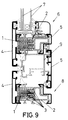
- FIG 9 one can see a practical embodiment of a pivoting window with the sections (4) defining the external part and sections (5) defining the internal part, and whose window has the corresponding leaf (6) for assembling the glass (7) and frame (8) with regard to which the leaf turns, the leaf (6) as well as the frame (8) being provided with bodies (1) and (2) with the projections (3) and corresponding recesses for pressure coupling or "clipping" of such bodies (1) and (2), joining together, once sections (4) and (5) that comprise the external part and the internal part, respectively, have been conveniently fastened to bodies (1) and (2), being complemented with other inside sections (9) for connecting the different parts to form the structure of said pivoting window unit.
- one of the bodies (1) or (2), or both of them may be made out of the same or different material, while sections (4) and (5) that constitute the inside part and the outside part and that are connected to bodies (1) and (2) may also be of identical or different material.
- a structure like the one represented in figure 9 can be complemented with the injection of insulating material such as polyurethane, providing the unit with thermal insulation and/or sound-proofing and it can even be complemented with the insertion of a sheet of steel in order to make the same reinforced.
- insulating material such as polyurethane
Landscapes
- Engineering & Computer Science (AREA)
- Civil Engineering (AREA)
- Structural Engineering (AREA)
- Securing Of Glass Panes Or The Like (AREA)
Abstract
The system is based on the use of two bodies (1) and (2) provided with projections (3) staggered with recesses, complementary in both bodies to permit pressure coupling of both bodies (1) and (2), with the possibility of axial movement to enable disassembly thereof. The bodies (1) and (2) can be made out of any suitable material and form together the structure corresponding to a closure of a window, door or the like, in such a way that the body (1) will constitute the part considered as external and body (2) will form the internal part of that structure, any of them being interchangeable as they are removable. In the case of structures with a thermal bridge any of the bodies (1) and (2) or both of them can constitute that which is the thermal bridge and can be fastened to the sections that will constitute the internal and/or external parts.
The possibility of this coupling of the bodies (1) and (2) permits any of the parts or bodies that form the closure to be interchanged, while the remaining ones are maintained.
Description
- As is expressed in the title of this specification, the present invention refers to a modular system for the formation of glass-enclosed closures, which may be: doors, windows, dividers, facades, furniture and/or any type of structure for purposes similar to those of the cited components.
- The basic characteristic of the modular system lies on the fact that the sole section that conventionally forms the structure of, for example, a door or window frame, is defined by two parts that can be coupled together, the coupling being defined by a special shape that permits assembly or disassembly to be carried out, thus enabling the interchange and thus the inside of the structure is of a certain color or material and the outside one is different. This system even permits the change to be made whenever one so desires, even in the event that the closure has been assembled for some time.
- Conventionally, steelwork closures, such as doors, windows, dividers, even facades, in the event of being simple closures, the structure or section on which the glass is mounted, is a single piece, in which the corresponding guides are formed, as well as the inside and outside surfaces of the section or structure itself. In the case of sections with a thermal bridge, there are logically two pieces, one that constitutes the inside part and the other that constitutes the outside part, with the insertion of the middle piece or pieces that define the thermal bridge itself.
- The fastening of these middle pieces constituting the thermal bridge with regard to the outside and inside sections, requires the use of some special pieces or machines to carry out the fastening or assembling between the different parts or pieces that constitute the structure, so that once the fastening or assembling has been carried out it is totally impossible to disassemble the same.
- Now then, for simple sections as well as for sections with a thermal bridge, irrespective of the assembly operations in the second case, the structure must be assembled at the factory and is taken to the installation site already assembled, which implies serious inconveniences when storage and transporation take place, due to the large space taken up by structures already mounted.
- Besides, due to the impossibility to disassemble the parts that make up the structure, the combination of materials, concerning colors as well as the nature of the same, is not possible, since a possible change inevitably requires the need to eliminate the original structure and to install an entire new one.
- The modular system for the formation of glass-enclosed closures object of the invention has the particularity that the basic section is divided into two parts, which may be made out of different materials and even of different colors, with the particularity that the two parts can be coupled together and taken apart in order to permit the color, material, etc. to be interchanged, by simply replacing the section or part that is to be renewed by another one, keeping the rest, which obviously cannot be done in conventional systems.
- In other words, in the system of the invention, the closure structure is formed by two totally independent parts or sections, one comprising the external body and the other one constituting the internal body, with the particularity that the two bodies can form the simple section, or else they can be connected to others to form structures or sections with a thermal bridge, it being provided for that the basic bodies or parts of the system may be made out of the same or different material.
- In this sense, the material used to manufacture the bodies or parts that comprise the structure or system may be steel, light-weight metals, heavy-weight metals, plastic, compound materials, processed quarry materials, etc. and bodies made of different materials may be mounted very easily, which permits combined systems to be obtained and permits a broader range of goods to be offered to consumers.
- The assembling system between the two basic parts or bodies is based on some complementary projections and recesses that are coupled by pressure, thus avoiding use of specific machinery for the assembly operation as is required in conventional systems, so that this coupling may be done "in situ", which makes it possible to take the bodies, sections or parts that form it separately, with the subsequent advantages when said structures are handled, stored and transported.
- These complementary projections and recesses for assembly of the two parts or bodies permit axial movement in terms of each other in order to carry out the corresponding disassembly, an operation which will be done manually, permitting any body or part to be replaced by another one of a different nature, color, etc.
- The fact that the structures that constitute the duly assembled sections permit injection of insulating products to meet the requirements of thermal insulation, soundproofing or they even permit a sheet of steel to be inserted in order to make the closure "reinforced" is also worth mentioning.
- In order to complement the description that is going to be made hereinafter and for the purpose of providing a better understanding of the characteristics of the invention, a set of drawings in which the innovations and advantages of the modular system for the formation of glass-enclosed closures object of the invention will be more easily understood is attached to the present specification.
- Figure 1.- It shows a cross-section view of the two separated bodies which are to form a section, for example, of a frame or leaf of a window.
- Figure 2.- It shows a section view of the two bodies represented in the above figure coupled together forming the section of the frame or lead of a window or the like.
- Figures 3, 4 and 5.- They show other views corresponding to separated sections and assembled sections of a section provided with a thermal bridge.
- Figures 6, 7 and 8.- They likewise show separated sections and assembled sections of two bodies constituting a section complemented by external finishing sections to form a structure that may or may not have a thermal bridge.
- Figure 9.- It shows a section view of the embodiment corresponding to the structure of a pivoting window made in accordance with the modular system object of the invention.
- In view of the figures commented on, and referring specifically to figures 1 and 2, one can observe how a section for the formation of a leaf or frame corresponding to a glass-enclosed closure, is comprised of two parts (1) and (2) that can be coupled together by means of "clipping", for which purpose body (1) as well as body (2) are provided with complementary projections (3) and a special shape between which recesses are logically made, so that confronting the projections and recesses (3) of bodies (1) and (2) permits the corresponding coupling by pressure connection, in other words by the above-mentioned "clipping", both bodies (1) and (2) remaining perfectly assembled, all so that bodies (1) and (2) are complemented with the corresponding suitable shape for forming that which corresponds to the external part (4) and the internal part (5) of the corresponding closure.
- These two bodies (1) and (2) constitute in their coupling or assembly a section as is clearly shown in figure 2, a section that may be made out of aluminum or any other suitable material. These may be the same or different from each other, so that the external part (4) may be of a color different from that of the internal part (5) or even out of different material.
- Therefore, the above mentioned bodies (1) and (2) coupled together constitute the metal section defining a simple structure, forming in these bodies (1) and (2) the external part (4) and the internal part (5) of the structure itself, the projections (3) being formed with their corresponding recesses so that the bodies (1) and (2) can move axially to each other and thus disassembly may be carried out.
- As one can see the projections (3) are made exactly in the same manner in both bodies, but in a reverse manner, thus making the coupling reversible, since it suffices to reverse the positioning of these bodies (1) and (2) to form that which is called the external part or the internal part of the general structure.
- Besides the simple structure that bodies (1) and (2) can form, structures with a thermal bridge like the one shown in figures (3) (4) and (5) can be formed, where the internal part can be comprised of the same body (2), while the external part (4) will be defined by the coupling of two bodies (1') and (4'), coupled together, so that the unit can be likewise coupled to the body (2) in the above mentioned manner. In other words, in this case bodies (1') and (2) have the same projections (3) for pressure coupling and their possibility of axial movement in order to carry out disassembly, with the particularity that the body (1') will be of a different material than body (2) in order to make the corresponding thermal bridge defined by these three bodies (1') (2) and (4') coupled together as shown in figure 5.
- In this case it is also possible to carry out the interchange of any of the three cited bodies (1'), (2) and (4'), either to replace the thermal body, or to change the color or material of body (2) forming the internal part, or else to interchange the external part (4), by means of interchanging the corresponding body (4'), and all on the basis of the possible disassembly by axial movement of some bodies with regard to each other.
- Figures 6, 7 and 8 show the two bodies (1) and (2) with their projections (3) defining the means for coupling together, and that can constitute on the whole a thermal bridge, either because they are made out of the same or different material, and in any case materials different from some complementary sections (4'') and (5'') that are going to constitute the external part (4) and the internal part (5), respectively, and whose complementary sections (4'') and (5'') can also be interchangeable and which are made from sheets of metal material that are formed by folding in order to define the corresponding sections. In other words, these sections (4'') and (5''), instead of being obtained by mechanizatiom, as usual, they are obtained from sheets that pass through suitable tools in order to make the suitable folds and to obtain the different shapes of the sections.
- In figure 9 one can see a practical embodiment of a pivoting window with the sections (4) defining the external part and sections (5) defining the internal part, and whose window has the corresponding leaf (6) for assembling the glass (7) and frame (8) with regard to which the leaf turns, the leaf (6) as well as the frame (8) being provided with bodies (1) and (2) with the projections (3) and corresponding recesses for pressure coupling or "clipping" of such bodies (1) and (2), joining together, once sections (4) and (5) that comprise the external part and the internal part, respectively, have been conveniently fastened to bodies (1) and (2), being complemented with other inside sections (9) for connecting the different parts to form the structure of said pivoting window unit.
- As it has already been said above, in the sections with thermal break bridge, one of the bodies (1) or (2), or both of them, may be made out of the same or different material, while sections (4) and (5) that constitute the inside part and the outside part and that are connected to bodies (1) and (2) may also be of identical or different material.
- Finally it is to be said that a structure like the one represented in figure 9 can be complemented with the injection of insulating material such as polyurethane, providing the unit with thermal insulation and/or sound-proofing and it can even be complemented with the insertion of a sheet of steel in order to make the same reinforced.
Claims (6)
- Modular system for the formation of glass-enclosed closures, which are to be used in the formation of frames, leaves and the like, of doors, windows, dividers or any other structure formed by means of a metal section with the corresponding shape for assembling glass and sealing molding, in the case of simple structures, or else the structure is formed by two section between which there is a middle piece of a different material, defining a thermal break bridge, essentially characterized in that the metal section comprising the simple structure is formed by two bodies (1) and (2) that can be coupled together with a removable nature, said bodies (1) and (2) forming the internal part (5) and the external part (4) of the structure itself, the latter having the possibility to be interchanged with others by virtue of the removable nature of the bodies (1) and (2) that form them; with the particularity that said two bodies have their coupling fronts provided with complementary recesses and projections (3), which adjust and link together by pressure in order to permit their disassembly by axial movement of one body with regard to the other; it also being provided for that these coupling projections (3) and recesses are materialized antagonistically in both bodies, making the coupling reversible, reversing the positioning of the body in its arrangement on either side of the structure that they form.
- Modular system for the formation of glass-enclosed closures, according to claim 1, characterized in that in structures with a thermal break bridge, one of the two pieces or both of them which constitute the bridge is/are materialized by the body or bodies (1) and (2) which, being of a different material, have the corresponding coupling means formed by the complementary recesses and projections (3.)
- Modular system for the formation of glass-enclosed closures, according to the above claims, characterized in that the two bodies (1) and (2) of different material, for the formation of the thermal break bridge, provided with complementary coupling projections (3) and recesses, are linked to both sections (4'') and (5'') that are identical to each other or different from each other, forming the inside part (5) and outside part (4) of the structure.
- Modular system for the formation of glass-enclosed closures, according to the above claims, characterized in that the two bodies (1) and (2) that can be coupled of the simple structure are metallic.
- Modular system for the formation of glass-enclosed closures, according to the above claims, characterized in that the body constituting the thermal break bridge (1') is made of different material than the opposite body (2) and can be coupled to it, that body (1') being connected to a section (4') of a nature identical to or different from that of the opposite body (2) and forming the other section.
- Modular system for the formation of glass-enclosed closures, according to the above claims, characterized in that the two bodies (1) and (2) that can be coupled together that form the thermal break bridge have an identical or a different nature, and in both eases of a nature different from that of the sections (4'') and (5'') connected to them and constituting the inside part (5) and outside part (4) of the structure, said sections either being of the same or a different nature.
Applications Claiming Priority (2)
| Application Number | Priority Date | Filing Date | Title |
|---|---|---|---|
| ES9302528 | 1993-12-02 | ||
| ES9302528A ES2076881B1 (en) | 1993-12-02 | 1993-12-02 | MODULAR SYSTEM FOR THE FORMATION OF GLASS ENCLOSURES. |
Publications (1)
| Publication Number | Publication Date |
|---|---|
| EP0657612A1 true EP0657612A1 (en) | 1995-06-14 |
Family
ID=8283814
Family Applications (1)
| Application Number | Title | Priority Date | Filing Date |
|---|---|---|---|
| EP94201879A Withdrawn EP0657612A1 (en) | 1993-12-02 | 1994-06-30 | Modular system for the formation of glass-enclosed closures |
Country Status (2)
| Country | Link |
|---|---|
| EP (1) | EP0657612A1 (en) |
| ES (1) | ES2076881B1 (en) |
Cited By (17)
| Publication number | Priority date | Publication date | Assignee | Title |
|---|---|---|---|---|
| EP0814228A2 (en) * | 1996-06-18 | 1997-12-29 | H. Hüttenbrauck GmbH u. Co. Profil- Walz- und Presswerk | Reinforcement profile for hollow plastic profiles for the production of windows, doors or the like |
| EP0829609A2 (en) * | 1996-09-17 | 1998-03-18 | SCHÜCO International KG | Heat-insulating compound profile for doors, windows or facades |
| WO1999032751A1 (en) * | 1997-12-19 | 1999-07-01 | James Hardie Research Pty. Limited | Building elements |
| DE10006612A1 (en) * | 2000-02-15 | 2001-08-30 | Guenther Hermann Seuffert | Plastic profile used as supporting part in window casement, cover frame or door profile, includes foam core and pockets for reinforcing or connection parts |
| AU738498B2 (en) * | 1997-12-19 | 2001-09-20 | Trend Windows & Doors Pty Limited | Building elements |
| WO2004079139A1 (en) * | 2003-03-05 | 2004-09-16 | Strato S.R.L. | Multiple structure profile for door and window frames provided with outer interchangeable section bars |
| DE10321685A1 (en) * | 2003-05-14 | 2004-12-30 | Sfs Handels Holding Ag | Frameless door or window sash with glass plates has glass plates located at inner and outer sides, and inner profile and outer profile formed with projections and indentations for positive and direct engagement with each other |
| EP1640548A2 (en) * | 2004-09-24 | 2006-03-29 | Giampiero Fabbri | Connection for composite profiles of door and window frames |
| FR2922990A1 (en) * | 2007-10-31 | 2009-05-01 | Norsk Hydro As | INSULATING BAR, PROFILE TYPE, FOR ASSOCIATED WITH A METAL BAR, OF PROFILE TYPE, BY A COMPLETE CONNECTION, AND CONSTRUCTION BAR SO OBTAINED |
| US7913470B2 (en) | 2007-04-02 | 2011-03-29 | Technoform Caprano Und Brunnhofer Gmbh & Co. Kg | Insulating strip for supporting a composite structure |
| US8584426B2 (en) | 2010-06-04 | 2013-11-19 | Milgard Manufacturing Incorporated | Sash binder |
| ITUD20120195A1 (en) * | 2012-11-20 | 2014-05-21 | Serrametal S R L | "WINDOW" |
| ITBA20130028A1 (en) * | 2013-04-16 | 2014-10-17 | Carmine Capece | FIXTURE FOR PASSIVE HOUSES EQUIPPED WITH INTERCHANGEABLE MODULAR COUPLING BOTH ON THE OUTSIDE SIDE, AND ON THE INTERNAL SIDE |
| EP3246505B1 (en) * | 2016-05-17 | 2019-09-25 | SCHÜCO International KG | Composite profile for doors, window or façade elements |
| EP4036360A1 (en) * | 2021-01-28 | 2022-08-03 | Garner Aluminium Extrusions Limited | A window frame assembly |
| GB2604579A (en) * | 2021-01-28 | 2022-09-14 | Garner Aluminium Extrusions Ltd | A window frame assembly |
| EP4434717A1 (en) * | 2023-03-24 | 2024-09-25 | Technoform Bautec Holding GmbH | Calibration device and method for calibrating an extruded plastic profile strand |
Citations (5)
| Publication number | Priority date | Publication date | Assignee | Title |
|---|---|---|---|---|
| GB1036480A (en) * | 1963-12-13 | 1966-07-20 | Meta Phronts Company Ltd | Improvements in or relating to frame members for making window and door frames and like structures |
| FR2372304A1 (en) * | 1976-11-25 | 1978-06-23 | Bierlich J H | Double glazed door or window frame - has ribbed extruded heat insulating strip between metal bar channel side stops (NL 29.5.78) |
| DE2908950A1 (en) * | 1979-03-07 | 1980-09-18 | Schuermann & Co Heinz | METHOD FOR PRODUCING A HEAT-INSULATED DOOR LEAF AND DOOR LEAF FRAME |
| GB2107774A (en) * | 1981-10-08 | 1983-05-05 | Duraflex Housecrafts Limited | Sectional frame members |
| WO1991010801A1 (en) * | 1990-01-11 | 1991-07-25 | Gasser Metallbau Des Gasser Erwin | Connecting system for producing composite profiles |
Family Cites Families (1)
| Publication number | Priority date | Publication date | Assignee | Title |
|---|---|---|---|---|
| IT225285Z2 (en) * | 1991-09-13 | 1996-10-24 | COMPOSITE PROFILE FOR WINDOWS |
-
1993
- 1993-12-02 ES ES9302528A patent/ES2076881B1/en not_active Expired - Lifetime
-
1994
- 1994-06-30 EP EP94201879A patent/EP0657612A1/en not_active Withdrawn
Patent Citations (5)
| Publication number | Priority date | Publication date | Assignee | Title |
|---|---|---|---|---|
| GB1036480A (en) * | 1963-12-13 | 1966-07-20 | Meta Phronts Company Ltd | Improvements in or relating to frame members for making window and door frames and like structures |
| FR2372304A1 (en) * | 1976-11-25 | 1978-06-23 | Bierlich J H | Double glazed door or window frame - has ribbed extruded heat insulating strip between metal bar channel side stops (NL 29.5.78) |
| DE2908950A1 (en) * | 1979-03-07 | 1980-09-18 | Schuermann & Co Heinz | METHOD FOR PRODUCING A HEAT-INSULATED DOOR LEAF AND DOOR LEAF FRAME |
| GB2107774A (en) * | 1981-10-08 | 1983-05-05 | Duraflex Housecrafts Limited | Sectional frame members |
| WO1991010801A1 (en) * | 1990-01-11 | 1991-07-25 | Gasser Metallbau Des Gasser Erwin | Connecting system for producing composite profiles |
Cited By (26)
| Publication number | Priority date | Publication date | Assignee | Title |
|---|---|---|---|---|
| EP0814228A2 (en) * | 1996-06-18 | 1997-12-29 | H. Hüttenbrauck GmbH u. Co. Profil- Walz- und Presswerk | Reinforcement profile for hollow plastic profiles for the production of windows, doors or the like |
| EP0814228A3 (en) * | 1996-06-18 | 1998-05-20 | H. Hüttenbrauck GmbH u. Co. Profil- Walz- und Presswerk | Reinforcement profile for hollow plastic profiles for the production of windows, doors or the like |
| EP0829609A2 (en) * | 1996-09-17 | 1998-03-18 | SCHÜCO International KG | Heat-insulating compound profile for doors, windows or facades |
| EP0829609A3 (en) * | 1996-09-17 | 1998-11-18 | SCHÜCO International KG | Heat-insulating compound profile for doors, windows or facades |
| AU738498B2 (en) * | 1997-12-19 | 2001-09-20 | Trend Windows & Doors Pty Limited | Building elements |
| WO1999032751A1 (en) * | 1997-12-19 | 1999-07-01 | James Hardie Research Pty. Limited | Building elements |
| DE10006612A1 (en) * | 2000-02-15 | 2001-08-30 | Guenther Hermann Seuffert | Plastic profile used as supporting part in window casement, cover frame or door profile, includes foam core and pockets for reinforcing or connection parts |
| WO2004079139A1 (en) * | 2003-03-05 | 2004-09-16 | Strato S.R.L. | Multiple structure profile for door and window frames provided with outer interchangeable section bars |
| DE10321685A1 (en) * | 2003-05-14 | 2004-12-30 | Sfs Handels Holding Ag | Frameless door or window sash with glass plates has glass plates located at inner and outer sides, and inner profile and outer profile formed with projections and indentations for positive and direct engagement with each other |
| DE10321685B4 (en) * | 2003-05-14 | 2006-03-30 | Sfs Handels Holding Ag | Door or casement with a double glazing |
| EP1640548A2 (en) * | 2004-09-24 | 2006-03-29 | Giampiero Fabbri | Connection for composite profiles of door and window frames |
| EP1640548A3 (en) * | 2004-09-24 | 2006-06-07 | Giampiero Fabbri | Connection for composite profiles of door and window frames |
| US7913470B2 (en) | 2007-04-02 | 2011-03-29 | Technoform Caprano Und Brunnhofer Gmbh & Co. Kg | Insulating strip for supporting a composite structure |
| FR2922990A1 (en) * | 2007-10-31 | 2009-05-01 | Norsk Hydro As | INSULATING BAR, PROFILE TYPE, FOR ASSOCIATED WITH A METAL BAR, OF PROFILE TYPE, BY A COMPLETE CONNECTION, AND CONSTRUCTION BAR SO OBTAINED |
| US8584426B2 (en) | 2010-06-04 | 2013-11-19 | Milgard Manufacturing Incorporated | Sash binder |
| ITUD20120195A1 (en) * | 2012-11-20 | 2014-05-21 | Serrametal S R L | "WINDOW" |
| WO2014079556A1 (en) | 2012-11-20 | 2014-05-30 | Serrametal S.R.L. | Frame |
| CN104919124A (en) * | 2012-11-20 | 2015-09-16 | 塞拉金属有限责任公司 | Frame |
| RU2639626C2 (en) * | 2012-11-20 | 2017-12-21 | Серраметал С.Р.Л. | Frame |
| CN104919124B (en) * | 2012-11-20 | 2018-06-15 | 塞拉金属有限责任公司 | Frame |
| ITBA20130028A1 (en) * | 2013-04-16 | 2014-10-17 | Carmine Capece | FIXTURE FOR PASSIVE HOUSES EQUIPPED WITH INTERCHANGEABLE MODULAR COUPLING BOTH ON THE OUTSIDE SIDE, AND ON THE INTERNAL SIDE |
| EP3246505B1 (en) * | 2016-05-17 | 2019-09-25 | SCHÜCO International KG | Composite profile for doors, window or façade elements |
| EP4036360A1 (en) * | 2021-01-28 | 2022-08-03 | Garner Aluminium Extrusions Limited | A window frame assembly |
| GB2604579A (en) * | 2021-01-28 | 2022-09-14 | Garner Aluminium Extrusions Ltd | A window frame assembly |
| EP4434717A1 (en) * | 2023-03-24 | 2024-09-25 | Technoform Bautec Holding GmbH | Calibration device and method for calibrating an extruded plastic profile strand |
| WO2024200028A1 (en) | 2023-03-24 | 2024-10-03 | Technoform Bautec Holding Gmbh | Calibration device for an extruded plastic profile strand and method for calibrating an extruded plastic profile strand and calibrated plastic profile |
Also Published As
| Publication number | Publication date |
|---|---|
| ES2076881R (en) | 1998-02-01 |
| ES2076881B1 (en) | 1998-09-01 |
| ES2076881A2 (en) | 1995-11-01 |
Similar Documents
| Publication | Publication Date | Title |
|---|---|---|
| EP0657612A1 (en) | Modular system for the formation of glass-enclosed closures | |
| EP3388608B1 (en) | Sliding element with sealing device and sealing element | |
| DE69000741T2 (en) | PROFILE ELEMENT FOR DOOR LEAFS. | |
| EP1877640B1 (en) | Frame for a window or a door | |
| WO1994025716A1 (en) | Composite section | |
| EP1674649A1 (en) | Two-part connecting section for plaster adjoining construction elements | |
| DE102010023607C5 (en) | Thermally insulated profile for sliding doors | |
| DE19731064C2 (en) | Aluminum mounting frame for door openings or the like | |
| DE202013102945U1 (en) | Door with a wing-covering door panel | |
| EP3002403A1 (en) | Window element | |
| DE9422032U1 (en) | Thermally insulated composite profile for window, door frames or the like. | |
| CA2312605A1 (en) | Window gate | |
| EP1184533B1 (en) | Low-energy house window | |
| SE462867B (en) | FRAME CONSTRUCTION CONSISTING OF FRAME PARTS AND WITH THESE FRONT ASSEMBLY | |
| EP0780525A1 (en) | Façade construction | |
| DE10117427B4 (en) | Door frames for sectional doors | |
| EP0658675A1 (en) | Door frame, particularly cladding therefor | |
| DE10251431A1 (en) | Door for installation in door aperture in house has hinges connecting moving frame to fixed frame, with frame elements made of hollow profiles | |
| US20090049755A1 (en) | Stepped frames for steel closures | |
| EP1811112A2 (en) | Glass bonding | |
| EP1152096A2 (en) | The perfected hidden union applicable to insulation panels and similar products | |
| ITPD950067A1 (en) | LOCKING SYSTEM FOR VEHICLE LOADING DOORS INCLUDING HINGES, ROTATION PINS, LOCKING RODS | |
| DE10047559C2 (en) | fitting | |
| DE7716996U1 (en) | PROFILE BAR UNIT | |
| DE3337310A1 (en) | Sealing arrangement at the opening of a thermally insulated container |
Legal Events
| Date | Code | Title | Description |
|---|---|---|---|
| PUAI | Public reference made under article 153(3) epc to a published international application that has entered the european phase |
Free format text: ORIGINAL CODE: 0009012 |
|
| AK | Designated contracting states |
Kind code of ref document: A1 Designated state(s): AT BE CH DE DK FR GB GR IE IT LI NL PT SE |
|
| 17P | Request for examination filed |
Effective date: 19951213 |
|
| 17Q | First examination report despatched |
Effective date: 19970409 |
|
| STAA | Information on the status of an ep patent application or granted ep patent |
Free format text: STATUS: THE APPLICATION IS DEEMED TO BE WITHDRAWN |
|
| 18D | Application deemed to be withdrawn |
Effective date: 19971021 |