EP0657549B1 - Process for producing an iron melt - Google Patents
Process for producing an iron melt Download PDFInfo
- Publication number
- EP0657549B1 EP0657549B1 EP94890201A EP94890201A EP0657549B1 EP 0657549 B1 EP0657549 B1 EP 0657549B1 EP 94890201 A EP94890201 A EP 94890201A EP 94890201 A EP94890201 A EP 94890201A EP 0657549 B1 EP0657549 B1 EP 0657549B1
- Authority
- EP
- European Patent Office
- Prior art keywords
- fine
- grained
- several
- iron
- solids
- Prior art date
- Legal status (The legal status is an assumption and is not a legal conclusion. Google has not performed a legal analysis and makes no representation as to the accuracy of the status listed.)
- Expired - Lifetime
Links
- XEEYBQQBJWHFJM-UHFFFAOYSA-N Iron Chemical compound [Fe] XEEYBQQBJWHFJM-UHFFFAOYSA-N 0.000 title claims description 100
- 229910052742 iron Inorganic materials 0.000 title claims description 50
- 238000000034 method Methods 0.000 title claims description 45
- 239000007789 gas Substances 0.000 claims description 58
- 239000002893 slag Substances 0.000 claims description 54
- 238000010891 electric arc Methods 0.000 claims description 38
- 239000007787 solid Substances 0.000 claims description 36
- 239000000969 carrier Substances 0.000 claims description 32
- 239000000428 dust Substances 0.000 claims description 28
- 229910000831 Steel Inorganic materials 0.000 claims description 23
- 239000010959 steel Substances 0.000 claims description 23
- OKTJSMMVPCPJKN-UHFFFAOYSA-N Carbon Chemical compound [C] OKTJSMMVPCPJKN-UHFFFAOYSA-N 0.000 claims description 21
- 239000003245 coal Substances 0.000 claims description 20
- 239000000203 mixture Substances 0.000 claims description 20
- 229910052799 carbon Inorganic materials 0.000 claims description 18
- 238000007664 blowing Methods 0.000 claims description 15
- 238000004519 manufacturing process Methods 0.000 claims description 12
- 239000000463 material Substances 0.000 claims description 11
- QVGXLLKOCUKJST-UHFFFAOYSA-N atomic oxygen Chemical compound [O] QVGXLLKOCUKJST-UHFFFAOYSA-N 0.000 claims description 10
- 239000003638 chemical reducing agent Substances 0.000 claims description 10
- VNWKTOKETHGBQD-UHFFFAOYSA-N methane Chemical compound C VNWKTOKETHGBQD-UHFFFAOYSA-N 0.000 claims description 10
- 229910052760 oxygen Inorganic materials 0.000 claims description 10
- 239000001301 oxygen Substances 0.000 claims description 10
- CURLTUGMZLYLDI-UHFFFAOYSA-N Carbon dioxide Chemical compound O=C=O CURLTUGMZLYLDI-UHFFFAOYSA-N 0.000 claims description 7
- 239000003570 air Substances 0.000 claims description 6
- 239000012159 carrier gas Substances 0.000 claims description 6
- 229930195733 hydrocarbon Natural products 0.000 claims description 6
- 150000002430 hydrocarbons Chemical class 0.000 claims description 6
- 229910002092 carbon dioxide Inorganic materials 0.000 claims description 5
- XLYOFNOQVPJJNP-UHFFFAOYSA-N water Substances O XLYOFNOQVPJJNP-UHFFFAOYSA-N 0.000 claims description 5
- XKRFYHLGVUSROY-UHFFFAOYSA-N Argon Chemical compound [Ar] XKRFYHLGVUSROY-UHFFFAOYSA-N 0.000 claims description 4
- IJGRMHOSHXDMSA-UHFFFAOYSA-N Atomic nitrogen Chemical compound N#N IJGRMHOSHXDMSA-UHFFFAOYSA-N 0.000 claims description 4
- 238000011010 flushing procedure Methods 0.000 claims description 4
- 238000005259 measurement Methods 0.000 claims description 4
- 239000003345 natural gas Substances 0.000 claims description 4
- 239000004215 Carbon black (E152) Substances 0.000 claims description 3
- 238000006243 chemical reaction Methods 0.000 claims description 3
- 239000000571 coke Substances 0.000 claims description 3
- 239000000155 melt Substances 0.000 claims description 3
- 230000001590 oxidative effect Effects 0.000 claims description 3
- 239000000161 steel melt Substances 0.000 claims description 3
- 230000001133 acceleration Effects 0.000 claims description 2
- 229910052786 argon Inorganic materials 0.000 claims description 2
- 239000001569 carbon dioxide Substances 0.000 claims description 2
- 229910001567 cementite Inorganic materials 0.000 claims description 2
- 229910052757 nitrogen Inorganic materials 0.000 claims description 2
- 239000008188 pellet Substances 0.000 claims description 2
- 230000002093 peripheral effect Effects 0.000 claims description 2
- 239000011449 brick Substances 0.000 claims 1
- 239000002002 slurry Substances 0.000 claims 1
- 229920002994 synthetic fiber Polymers 0.000 claims 1
- 239000002023 wood Substances 0.000 claims 1
- 239000006260 foam Substances 0.000 description 26
- ODINCKMPIJJUCX-UHFFFAOYSA-N Calcium oxide Chemical compound [Ca]=O ODINCKMPIJJUCX-UHFFFAOYSA-N 0.000 description 20
- 239000000292 calcium oxide Substances 0.000 description 10
- 235000012255 calcium oxide Nutrition 0.000 description 10
- 229910052751 metal Inorganic materials 0.000 description 9
- 239000002184 metal Substances 0.000 description 9
- UQSXHKLRYXJYBZ-UHFFFAOYSA-N Iron oxide Chemical compound [Fe]=O UQSXHKLRYXJYBZ-UHFFFAOYSA-N 0.000 description 6
- 229910004298 SiO 2 Inorganic materials 0.000 description 6
- VYPSYNLAJGMNEJ-UHFFFAOYSA-N Silicium dioxide Chemical compound O=[Si]=O VYPSYNLAJGMNEJ-UHFFFAOYSA-N 0.000 description 6
- 239000010439 graphite Substances 0.000 description 6
- 229910002804 graphite Inorganic materials 0.000 description 6
- 239000007788 liquid Substances 0.000 description 6
- 238000002844 melting Methods 0.000 description 6
- 230000008018 melting Effects 0.000 description 6
- 238000003723 Smelting Methods 0.000 description 5
- 229910052593 corundum Inorganic materials 0.000 description 5
- 229910018072 Al 2 O 3 Inorganic materials 0.000 description 4
- 238000011084 recovery Methods 0.000 description 4
- 238000010079 rubber tapping Methods 0.000 description 4
- 229910052717 sulfur Inorganic materials 0.000 description 4
- PNEYBMLMFCGWSK-UHFFFAOYSA-N aluminium oxide Inorganic materials [O-2].[O-2].[O-2].[Al+3].[Al+3] PNEYBMLMFCGWSK-UHFFFAOYSA-N 0.000 description 3
- 229910002091 carbon monoxide Inorganic materials 0.000 description 3
- 229910052681 coesite Inorganic materials 0.000 description 3
- 238000002485 combustion reaction Methods 0.000 description 3
- 229910052906 cristobalite Inorganic materials 0.000 description 3
- 229910052739 hydrogen Inorganic materials 0.000 description 3
- 239000011261 inert gas Substances 0.000 description 3
- 238000012545 processing Methods 0.000 description 3
- 239000000377 silicon dioxide Substances 0.000 description 3
- 229910052682 stishovite Inorganic materials 0.000 description 3
- 229910052905 tridymite Inorganic materials 0.000 description 3
- 239000002699 waste material Substances 0.000 description 3
- 229910001845 yogo sapphire Inorganic materials 0.000 description 3
- 235000008733 Citrus aurantifolia Nutrition 0.000 description 2
- 235000011941 Tilia x europaea Nutrition 0.000 description 2
- 239000000654 additive Substances 0.000 description 2
- 239000003575 carbonaceous material Substances 0.000 description 2
- 239000010431 corundum Substances 0.000 description 2
- 230000005611 electricity Effects 0.000 description 2
- 238000009434 installation Methods 0.000 description 2
- 239000004571 lime Substances 0.000 description 2
- 230000000149 penetrating effect Effects 0.000 description 2
- 239000004033 plastic Substances 0.000 description 2
- 238000004064 recycling Methods 0.000 description 2
- 230000001105 regulatory effect Effects 0.000 description 2
- 229910004261 CaF 2 Inorganic materials 0.000 description 1
- VTYYLEPIZMXCLO-UHFFFAOYSA-L Calcium carbonate Chemical compound [Ca+2].[O-]C([O-])=O VTYYLEPIZMXCLO-UHFFFAOYSA-L 0.000 description 1
- UGFAIRIUMAVXCW-UHFFFAOYSA-N Carbon monoxide Chemical compound [O+]#[C-] UGFAIRIUMAVXCW-UHFFFAOYSA-N 0.000 description 1
- 229910001341 Crude steel Inorganic materials 0.000 description 1
- 229910005347 FeSi Inorganic materials 0.000 description 1
- 229920000426 Microplastic Polymers 0.000 description 1
- 241001062472 Stokellia anisodon Species 0.000 description 1
- 229910010413 TiO 2 Inorganic materials 0.000 description 1
- 239000003513 alkali Substances 0.000 description 1
- RHZUVFJBSILHOK-UHFFFAOYSA-N anthracen-1-ylmethanolate Chemical compound C1=CC=C2C=C3C(C[O-])=CC=CC3=CC2=C1 RHZUVFJBSILHOK-UHFFFAOYSA-N 0.000 description 1
- 239000003830 anthracite Substances 0.000 description 1
- 230000015572 biosynthetic process Effects 0.000 description 1
- WUKWITHWXAAZEY-UHFFFAOYSA-L calcium difluoride Chemical compound [F-].[F-].[Ca+2] WUKWITHWXAAZEY-UHFFFAOYSA-L 0.000 description 1
- 229910001634 calcium fluoride Inorganic materials 0.000 description 1
- 238000005255 carburizing Methods 0.000 description 1
- 238000005266 casting Methods 0.000 description 1
- 229910052804 chromium Inorganic materials 0.000 description 1
- 239000002817 coal dust Substances 0.000 description 1
- 230000001143 conditioned effect Effects 0.000 description 1
- 239000000470 constituent Substances 0.000 description 1
- 238000010924 continuous production Methods 0.000 description 1
- 230000001276 controlling effect Effects 0.000 description 1
- 239000000112 cooling gas Substances 0.000 description 1
- 239000000498 cooling water Substances 0.000 description 1
- 238000013461 design Methods 0.000 description 1
- 238000005265 energy consumption Methods 0.000 description 1
- 238000003912 environmental pollution Methods 0.000 description 1
- 210000003608 fece Anatomy 0.000 description 1
- -1 ferrous metals Chemical class 0.000 description 1
- 239000010436 fluorite Substances 0.000 description 1
- 238000005187 foaming Methods 0.000 description 1
- 239000002803 fossil fuel Substances 0.000 description 1
- 238000010438 heat treatment Methods 0.000 description 1
- 238000002347 injection Methods 0.000 description 1
- 239000007924 injection Substances 0.000 description 1
- JEIPFZHSYJVQDO-UHFFFAOYSA-N iron(III) oxide Inorganic materials O=[Fe]O[Fe]=O JEIPFZHSYJVQDO-UHFFFAOYSA-N 0.000 description 1
- 238000005304 joining Methods 0.000 description 1
- 238000012423 maintenance Methods 0.000 description 1
- 229910052748 manganese Inorganic materials 0.000 description 1
- 229910052750 molybdenum Inorganic materials 0.000 description 1
- 229910052759 nickel Inorganic materials 0.000 description 1
- 238000013021 overheating Methods 0.000 description 1
- 230000003647 oxidation Effects 0.000 description 1
- 238000007254 oxidation reaction Methods 0.000 description 1
- 229920003023 plastic Polymers 0.000 description 1
- 238000001556 precipitation Methods 0.000 description 1
- 238000010926 purge Methods 0.000 description 1
- 239000010802 sludge Substances 0.000 description 1
- 239000000126 substance Substances 0.000 description 1
- 231100000331 toxic Toxicity 0.000 description 1
- 230000002588 toxic effect Effects 0.000 description 1
Images
Classifications
-
- C—CHEMISTRY; METALLURGY
- C21—METALLURGY OF IRON
- C21B—MANUFACTURE OF IRON OR STEEL
- C21B13/00—Making spongy iron or liquid steel, by direct processes
- C21B13/0006—Making spongy iron or liquid steel, by direct processes obtaining iron or steel in a molten state
- C21B13/0013—Making spongy iron or liquid steel, by direct processes obtaining iron or steel in a molten state introduction of iron oxide into a bath of molten iron containing a carbon reductant
-
- C—CHEMISTRY; METALLURGY
- C21—METALLURGY OF IRON
- C21B—MANUFACTURE OF IRON OR STEEL
- C21B13/00—Making spongy iron or liquid steel, by direct processes
- C21B13/12—Making spongy iron or liquid steel, by direct processes in electric furnaces
-
- C—CHEMISTRY; METALLURGY
- C21—METALLURGY OF IRON
- C21C—PROCESSING OF PIG-IRON, e.g. REFINING, MANUFACTURE OF WROUGHT-IRON OR STEEL; TREATMENT IN MOLTEN STATE OF FERROUS ALLOYS
- C21C5/00—Manufacture of carbon-steel, e.g. plain mild steel, medium carbon steel or cast steel or stainless steel
- C21C5/52—Manufacture of steel in electric furnaces
- C21C5/527—Charging of the electric furnace
-
- C—CHEMISTRY; METALLURGY
- C22—METALLURGY; FERROUS OR NON-FERROUS ALLOYS; TREATMENT OF ALLOYS OR NON-FERROUS METALS
- C22B—PRODUCTION AND REFINING OF METALS; PRETREATMENT OF RAW MATERIALS
- C22B7/00—Working up raw materials other than ores, e.g. scrap, to produce non-ferrous metals and compounds thereof; Methods of a general interest or applied to the winning of more than two metals
- C22B7/02—Working-up flue dust
-
- F—MECHANICAL ENGINEERING; LIGHTING; HEATING; WEAPONS; BLASTING
- F27—FURNACES; KILNS; OVENS; RETORTS
- F27B—FURNACES, KILNS, OVENS OR RETORTS IN GENERAL; OPEN SINTERING OR LIKE APPARATUS
- F27B3/00—Hearth-type furnaces, e.g. of reverberatory type; Electric arc furnaces ; Tank furnaces
- F27B3/08—Hearth-type furnaces, e.g. of reverberatory type; Electric arc furnaces ; Tank furnaces heated electrically, with or without any other source of heat
- F27B3/085—Arc furnaces
-
- C—CHEMISTRY; METALLURGY
- C21—METALLURGY OF IRON
- C21C—PROCESSING OF PIG-IRON, e.g. REFINING, MANUFACTURE OF WROUGHT-IRON OR STEEL; TREATMENT IN MOLTEN STATE OF FERROUS ALLOYS
- C21C5/00—Manufacture of carbon-steel, e.g. plain mild steel, medium carbon steel or cast steel or stainless steel
- C21C5/28—Manufacture of steel in the converter
- C21C5/36—Processes yielding slags of special composition
- C21C2005/366—Foam slags
-
- F—MECHANICAL ENGINEERING; LIGHTING; HEATING; WEAPONS; BLASTING
- F27—FURNACES; KILNS; OVENS; RETORTS
- F27D—DETAILS OR ACCESSORIES OF FURNACES, KILNS, OVENS OR RETORTS, IN SO FAR AS THEY ARE OF KINDS OCCURRING IN MORE THAN ONE KIND OF FURNACE
- F27D3/00—Charging; Discharging; Manipulation of charge
- F27D3/16—Introducing a fluid jet or current into the charge
- F27D2003/161—Introducing a fluid jet or current into the charge through a porous element
-
- F—MECHANICAL ENGINEERING; LIGHTING; HEATING; WEAPONS; BLASTING
- F27—FURNACES; KILNS; OVENS; RETORTS
- F27D—DETAILS OR ACCESSORIES OF FURNACES, KILNS, OVENS OR RETORTS, IN SO FAR AS THEY ARE OF KINDS OCCURRING IN MORE THAN ONE KIND OF FURNACE
- F27D21/00—Arrangement of monitoring devices; Arrangement of safety devices
- F27D21/02—Observation or illuminating devices
- F27D2021/026—Observation or illuminating devices using a video installation
-
- F—MECHANICAL ENGINEERING; LIGHTING; HEATING; WEAPONS; BLASTING
- F27—FURNACES; KILNS; OVENS; RETORTS
- F27D—DETAILS OR ACCESSORIES OF FURNACES, KILNS, OVENS OR RETORTS, IN SO FAR AS THEY ARE OF KINDS OCCURRING IN MORE THAN ONE KIND OF FURNACE
- F27D21/00—Arrangement of monitoring devices; Arrangement of safety devices
- F27D21/0035—Devices for monitoring the weight of quantities added to the charge
-
- F—MECHANICAL ENGINEERING; LIGHTING; HEATING; WEAPONS; BLASTING
- F27—FURNACES; KILNS; OVENS; RETORTS
- F27D—DETAILS OR ACCESSORIES OF FURNACES, KILNS, OVENS OR RETORTS, IN SO FAR AS THEY ARE OF KINDS OCCURRING IN MORE THAN ONE KIND OF FURNACE
- F27D3/00—Charging; Discharging; Manipulation of charge
- F27D3/0025—Charging or loading melting furnaces with material in the solid state
- F27D3/0026—Introducing additives into the melt
-
- Y—GENERAL TAGGING OF NEW TECHNOLOGICAL DEVELOPMENTS; GENERAL TAGGING OF CROSS-SECTIONAL TECHNOLOGIES SPANNING OVER SEVERAL SECTIONS OF THE IPC; TECHNICAL SUBJECTS COVERED BY FORMER USPC CROSS-REFERENCE ART COLLECTIONS [XRACs] AND DIGESTS
- Y02—TECHNOLOGIES OR APPLICATIONS FOR MITIGATION OR ADAPTATION AGAINST CLIMATE CHANGE
- Y02A—TECHNOLOGIES FOR ADAPTATION TO CLIMATE CHANGE
- Y02A40/00—Adaptation technologies in agriculture, forestry, livestock or agroalimentary production
- Y02A40/90—Adaptation technologies in agriculture, forestry, livestock or agroalimentary production in food processing or handling, e.g. food conservation
- Y02A40/924—Adaptation technologies in agriculture, forestry, livestock or agroalimentary production in food processing or handling, e.g. food conservation using renewable energies
- Y02A40/928—Cooking stoves using biomass
-
- Y—GENERAL TAGGING OF NEW TECHNOLOGICAL DEVELOPMENTS; GENERAL TAGGING OF CROSS-SECTIONAL TECHNOLOGIES SPANNING OVER SEVERAL SECTIONS OF THE IPC; TECHNICAL SUBJECTS COVERED BY FORMER USPC CROSS-REFERENCE ART COLLECTIONS [XRACs] AND DIGESTS
- Y02—TECHNOLOGIES OR APPLICATIONS FOR MITIGATION OR ADAPTATION AGAINST CLIMATE CHANGE
- Y02P—CLIMATE CHANGE MITIGATION TECHNOLOGIES IN THE PRODUCTION OR PROCESSING OF GOODS
- Y02P10/00—Technologies related to metal processing
- Y02P10/10—Reduction of greenhouse gas [GHG] emissions
- Y02P10/134—Reduction of greenhouse gas [GHG] emissions by avoiding CO2, e.g. using hydrogen
-
- Y—GENERAL TAGGING OF NEW TECHNOLOGICAL DEVELOPMENTS; GENERAL TAGGING OF CROSS-SECTIONAL TECHNOLOGIES SPANNING OVER SEVERAL SECTIONS OF THE IPC; TECHNICAL SUBJECTS COVERED BY FORMER USPC CROSS-REFERENCE ART COLLECTIONS [XRACs] AND DIGESTS
- Y02—TECHNOLOGIES OR APPLICATIONS FOR MITIGATION OR ADAPTATION AGAINST CLIMATE CHANGE
- Y02P—CLIMATE CHANGE MITIGATION TECHNOLOGIES IN THE PRODUCTION OR PROCESSING OF GOODS
- Y02P10/00—Technologies related to metal processing
- Y02P10/20—Recycling
Definitions
- the invention relates to a method for producing a molten iron, in particular one Molten steel, in a reactor with power supply, e.g. an electric arc furnace, and an installation for carrying out the method.
- a reactor with power supply e.g. an electric arc furnace
- EP-A-0 418 656 describes a method for applying a molten metal to a gas and fine-grained solids, in which a gas through a first lance and the solids are fed as a flow via a second lance so that after the Leaving the outlet opening of the second lance of gas emerging from the first lance deflected and fed with this to the molten metal without it through Solids migrate to areas above the molten metal noteworthy losses.
- the converted coal can only be converted into CO to a very limited extent as an energy source act; a complete reduction is only here at high carbon contents and -consumption possible.
- the amount of solids to be introduced per blowing point is due to the unfavorable local energy generation very limited.
- EP-A-0 637 634 describes a method for producing a molten metal, in particular a molten steel, known in an electric arc furnace, in which the bath surface is covered with a foam slag during the flat bath period (s).
- a foam slag during the flat bath period (s).
- a level measurement is made several times during a furnace batch the layer height of a slag, and by blowing in and / or inflating Solids, gases or a mixture of solids and gases in and / or on the Slag or the molten metal an arc formed by at least one electrode enveloping foam slag formed, the layer height is such that the Foam slag extends at least over the entire arc.
- the invention aims at avoiding these disadvantages and difficulties and presents itself the task, a method of the type described above and a system for Implementation of the process to create a particularly economical recovery of fine-grained iron girders, especially of house dust, even in large ones Enable usage amounts, etc. while minimizing energy use, taking losses by moving the fine-grained iron carriers out of the electric furnace in unchanged form largely avoided, so that the recycling of the filter dust without any Environmental pollution is possible.
- the introduction of the fine-grained substances into the foam slag is of importance for the invention, since this makes it possible to avoid a reduction in the CO 2 produced when the iron carriers are reduced, as a result of which substantial energy savings can be achieved.
- the iron melt either represents a residual amount of steel from the previous melting period or is previously produced by melting lumpy iron carriers (possibly with the addition of liquid iron carriers). Plastics and graphite are also suitable as carbon-containing feedstocks.
- Inert and / or reducing and / or is preferably used to accelerate the process oxidizing gas introduced directly into the molten iron, preferably from below.
- An efficient process sequence can be achieved in that the fine-grained iron carriers, the fine-grained carbonaceous reducing agents and energy sources in several local limited peripheral areas of the reactor are introduced.
- the Layer height of the foam slag kept at a predetermined minimum value, preferably regulated to maintain the minimum value, expediently during a Oven batch several times or continuously a level measurement of the layer height of the Foam slag is carried out and by blowing and / or inflating solids, gases or a mixture of solids and gases in and / or on the foam slag or Iron smelt enveloping an arc formed by at least one electrode Foam slag is formed, the layer height of which is such that the Foam slag extends at least over the entire arc.
- the process according to the invention enables large quantities of fine-grained materials to be used Iron beams.
- the blow rate per minute for the fine-grained iron carriers is appropriate between one thousandth and a few hundredths of the tapping weight of the reactor, , u.zw. advantageous between 20 kg / min and 2000 kg / min.
- the fine-grained materials are advantageously fed pneumatically, with the conveying gas Oxygen, air, nitrogen, argon, hydrocarbons, such as natural gas, water vapor, Carbon dioxide or mixtures of these gases can be used.
- the conveying gas Oxygen, air, nitrogen, argon, hydrocarbons, such as natural gas, water vapor, Carbon dioxide or mixtures of these gases can be used.
- fine-grained iron carriers and optionally fine-grained carbonaceous materials by means of a carrier gas blown in at least one hollow electrode.
- Fine-grained iron carriers and fine-grained carbonaceous materials are useful by means of a carrier gas over at least one penetrating the side wall of the reactor Side lance and / or a pair of nozzles in the formed on the surface of the molten iron Blown in foam slag, with oxygen or oxygen-containing gases over at least a side lance and / or nozzle passing through the side wall of the reactor into the Foam slag is (are) blown.
- Lumpy materials can also be recycled using the method according to the invention. These are advantageous via one or more openings provided in the furnace cover Openings introduced.
- the sensible heat expediently becomes hotter and escapes from the electric arc furnace
- Exhaust gases for preheating at least a part of the electric arc furnace introduced solids and / or introduced gases.
- a system for performing the method is characterized by the features of claim 15 characterized.
- the supplied gas and the supplied Solids by means of at least one side lance passing through the side wall of the reactor feedable, the side lance up to the mouth separate flow cross sections for the Has gas and the solids.
- Another preferred embodiment is characterized in that at least one Electrode with a central longitudinal recess into which a fine-grained solids and / or Gas supply line opens, is provided.
- Nozzles or flushing stones are advantageously provided in the bottom of the reactor.
- the nozzles are preferably protected with natural gas.
- a level measuring device for measuring the layer height of those located on the iron melt Foam slag provided with a controlled system, which with the feed device for the Solids and / or gases and / or solid-gas mixtures is coupled.
- the mouths of the gas supply devices and the mouths of the Feeding devices for the fine-grained iron carriers, reducing agents and energy carriers directed obliquely downwards against the floor nozzles.
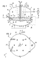
- FIG. 1 illustrates a vertical section through an inventive Arc furnace along the line I-I of Fig. 2
- Fig. 2 is a horizontal section of the same after the Line II-II of Fig. 1st
- an electric arc furnace 1 In an electric arc furnace 1, one protrudes centrally from above through its cover 2 self-consuming graphite electrode 3, the arc 4 against a the bottom 5 of the Electric arc furnace 1 covering molten steel 6 burns. In the bottom 5 is the Counter electrode 7 arranged.
- the embodiment shown is a DC arc furnace with only one electrode. However, there could be several self-consuming graphite electrodes 3 - as illustrated in dash-dotted lines - be provided, which could be operated with AC or three-phase current.
- the self-consuming graphite electrode 3 is designed as a hollow electrode. Through its inner central longitudinal recess 11, which is expediently provided with an inner lining made of Al 2 O 3 -containing pipes (corundum, Sillimanit etc.) or steel, 12 fine-grained solids and / or gases or mixtures of solids and gases can be supplied via the line are supplied, which then go directly into the electric arc 4.
- the lid 2 of the electric arc furnace 1 also has a lid opening 13 through which lumpy solids, lump coal or coke, lump ore, filter dust pellets or briquettes or additives, which are fed in via the feed line 14, are introduced into the interior 15 of the electric arc furnace 1 can.
- One or more protrude through the side wall 16 of the electric arc furnace 1 this either movable or rigid and either by cooling water or Cooling gas protected or - if not protected - self-consuming lances 17 in the Interior 15 of the electric arc furnace 1.
- the lances 17 are inclined in the operating position directed against the floor 5. They can be arranged movably in the side wall 16, u.zw. tiltable, swiveling and sliding and retractable. There is also a stationary installation conceivable in the side wall 16.
- the lances 17 each have separate flow cross sections 18, 19 for the mouth 20 the supply of gas and solids, so that with a gaseous medium solids conveyed to the orifice 20 are only at the or with the separately supplied gas mix after exiting the mouth.
- the orifices 20 of the lances 17 lie during the operation of the electric arc furnace 1 in a height range over which the Foam slag 9 extends
- the electric arc furnace 1 has its side wall 16 penetrating nozzle pairs 21, 22, the orifices 23, 24 of the nozzle pairs 21, 22 also lie in a height range over which the foam slag 9 extends.
- Each a pair of nozzles 21, 22 is formed by an upper nozzle 22 and one approximately vertically below this nozzle 22 lying further nozzle 21 is formed.
- the upper nozzle turns oxygen or a oxygen-containing gas and through the lower nozzle 21 fine-grained solids with the help of a conveying gas introduced into the interior 15 of the electric arc furnace 1.
- expedient the nozzles 21, 22 are also movably arranged in the side wall 16 (tiltable and forward and retractable).
- the electric arc furnace 1 has one according to the illustrated embodiment Floor tapping 26; however, a siphon tap could also be provided.
- the Slag tapping is indicated at 27.
- the exhaust gas that forms in the interior 15 of the electric arc furnace 1 is passed through a Exhaust pipe 28 fed to a filter system, not shown.
- the sensible warmth of Exhaust gases can subsequently be used to preheat at least part of the electric arc furnace 1 charged solids and / or introduced gases, etc. without or with partial afterburning of the exhaust gases.
- the preheating is done by the Exhaust gases through suitable preheating devices, e.g. a preheating shaft and / or Fluidized bed or rotary tube reactors and / or other heat exchangers are conducted.
- the height of the foam slag 9 can be measured by means of a level measuring device 29, e.g. as Sound measuring device, high temperature measuring device or a high temperature video camera or is designed as a high-temperature radar can be detected, the Measurement signal from the level measuring device for regulating the height 10 of the foam slag 9 is used, for example by feeding it to a controlled system 30, the Output signals control elements for controlling the introduced solids and / or gases and / or mixtures of solids and gases are transmitted. However, it could also be one Corresponding message to the operator at the furnace control station, whereupon this Control bodies in the appropriate position.
- a level measuring device 29 e.g. as Sound measuring device, high temperature measuring device or a high temperature video camera or is designed as a high-temperature radar can be detected
- the Measurement signal from the level measuring device for regulating the height 10 of the foam slag 9 is used, for example by feeding it to a controlled system 30, the Output signals control elements for controlling the introduced solids and / or gases and
- the fine-grained feed materials (filter dust and coal) were pneumatically ins up to 100% Bad 6 fed.
- the lumpy slag formers were added via the lid opening 13th
- steel scrap (a basket) was charged into the empty furnace and melted down with the electrode while blowing fine-grained coal and O 2 .
- the coal was introduced via the lances 17 and through the nozzles 21 of the lower level, the oxygen via the lances 17 and the nozzles 22 of the upper level.
- the temperature of the resulting steel sump (approx. 60 t) was then increased to 1620 ° C., its C content being 0.15%.
- the amount of furnace slag formed was approximately 6 t after the addition of slag formers.
- the blowing in of filter dust was started under these bath conditions.
- a filter dust-coal mixture was blown through the hollow electrode 3, the lances 17 and the nozzles 21 of the lower nozzle level using N 2 carrier gas below the surface 31 of the foam slag 9, but above the surface 8 of the steel bath 6.
- the blowing rate was 500 kg of filter dust / min, so that a total of 20 t of filter dust was blown in within 40 minutes.
- the foam slag 9 was also blown through the lances 17 and the nozzles 22 of the upper nozzle plane O 2 .
- N 2 + CH 4 was introduced through the bottom nozzles 25 as the bottom flushing gas.
- Lump lime was added through the lid opening 13.
- a well foaming slag 9 was obtained during the entire dust blowing period, which completely surrounded the arc 4 over almost the entire dust blowing period.
- the following bath conditions were achieved: temperature 1600 ⁇ 20 ° C (% C) 0.07 ⁇ 0.03 (% FeO n ) 20 ⁇ 5 (% CaO) / (% SiO 2 ) 2.2 ⁇ 0.2
- the amount of steel in the furnace was approx. 73 t.
- the amount of slag was approximately 7.5 t.
- the melt reduction of the iron carriers supplied is preferred according to the invention at a temperature between approx. 1500 and 1650 ° C
- the Foam slag 9 on the slag tapping 27 or the steel melt 6 produced on the Bottom cut 26 partially tapped from time to time (with interruption of the feed of electricity and fine-grained solids because of the electric arc furnace conditioned discontinuous process flow), so that a certain residual slag or a certain steel sump as a minimum quantity for the trouble-free continuation of the smelting reduction remains in the oven.
- a steel sump can also be melted by iron beams (too in pieces).
- the steel melt produced (crude steel) is replaced by others secondary metallurgical treatment to the desired composition and casting Brought temperature.
- the method according to the invention is in a conventional DC or AC electric arc furnace carried out, a discontinuous process is appropriate.
- a discontinuous process is appropriate.
- an electric arc furnace or an electric arc furnace-like Plant containing melt or melt reduction part for the production of liquid steel a continuous or semi-continuous process flow is also possible.
- the process can also be combined with the usual electric arc furnace mode of operation - as an additional process step or parallel to melting (e.g. from Scrap and / or sponge iron) and / or freshening or overheating the melt in the Flat bath operation - can be used.
- the fine-grained iron girders - in particular smelter dust (filter dust from the converter, Electric arc furnace, blast furnace, from smelting reduction plants etc.), fine ore with or without pre-reduction, iron carbide, DRE-fines, scale, dried and crushed sludge etc. - can according to the invention in discontinuous operation up to a proportion 80% of the total iron used are fed into the electric arc furnace and partially or completely by joining non-ferrous metals (e.g. Ni, Cr, Mo, Mn etc.) to be replaced.
- non-ferrous metals e.g. Ni, Cr, Mo, Mn etc.
- the fine-grained C-containing reducing agents preferably consist of coal, coke, graphite, Plastic, wood etc. or their mixtures. Inexpensive fine-grain FeSi, Al or others Reducing agents can also be used.
- the gases supplied consist of O 2 , air, N 2 , Ar, natural gas or other hydrocarbons, H 2 O (steam), CO 2 or mixtures thereof.
- Hydrocarbon can also be supplied in the liquid state.
- air or the inert gases can be preheated.
- the total coal consumption according to the invention results from the so-called “reduction coal” (sales coal) and the so-called “heating coal” (replacement for electrical energy).
- energy can be introduced with the aid of afterburning lances blowing on or into the slag, which are operated with O 2 and / or air.
- a major advantage of the method according to the invention is that a Processing and thus the disposal of resulting dust from the iron and steel at the same time Recovery and / or enrichment of their constituents (enrichment to concentrations, in which the further disposal of waste materials can be realized economically) is possible.
- One possible application of the method according to the invention is Disposal of toxic or environmentally harmful waste materials, such as shredder waste, Plastic granules, dried faeces etc., including the recovery of their valuable ones Components using their energy content ..
Landscapes
- Engineering & Computer Science (AREA)
- Chemical & Material Sciences (AREA)
- Metallurgy (AREA)
- Manufacturing & Machinery (AREA)
- Materials Engineering (AREA)
- Organic Chemistry (AREA)
- Mechanical Engineering (AREA)
- General Engineering & Computer Science (AREA)
- Life Sciences & Earth Sciences (AREA)
- Environmental & Geological Engineering (AREA)
- General Life Sciences & Earth Sciences (AREA)
- Geology (AREA)
- Vertical, Hearth, Or Arc Furnaces (AREA)
- Refinement Of Pig-Iron, Manufacture Of Cast Iron, And Steel Manufacture Other Than In Revolving Furnaces (AREA)
Description
Die Erfindung betrifft ein Verfahren zum Herstellen einer Eisenschmelze, insbesondere einer Stahlschmelze, in einem Reaktor mit Stromzufuhr, wie z.B. einem Elektro-Lichtbogenofen, sowie eine Anlage zur Durchführung des Verfahrens.The invention relates to a method for producing a molten iron, in particular one Molten steel, in a reactor with power supply, e.g. an electric arc furnace, and an installation for carrying out the method.
Es ist intern bekannt, bei der Stahlherstellung sich bildende Filterstäube mit Hilfe eines Inertgases durch Hohlelektroden in einen Elektro-Lichtbogenofen zur Herstellung von Stahl einzubringen. Hierbei hat sich jedoch gezeigt, daß eine Verwertung der Filterstäube, d.h. deren Verarbeitung zu Stahl, nicht möglich ist und ein großer Anteil der Filterstäube den Elektro-Lichtbogenofen mehr oder weniger unverändert wieder verläßt, so daß die aus den Filterstäuben resultierende Belastung der Umwelt nahezu unverändert weiter besteht.It is known internally that filter dusts are formed during the manufacture of steel using a Inert gas through hollow electrodes in an electric arc furnace for the production of steel contribute. However, it has been shown here that recycling of the filter dusts, i.e. their Processing to steel, is not possible and a large proportion of the filter dust the electric arc furnace leaves more or less unchanged, so that from the Filter dust resulting pollution of the environment remains almost unchanged.
Aus der EP-A - 0 418 656 ist ein Verfahren zum Beaufschlagen einer Metallschmelze mit einem Gas und feinkörnigen Feststoffen bekannt, bei dem ein Gas durch eine erste Lanze und die Feststoffe als Förderstrom über eine zweite Lanze so zugeführt werden, daß sie nach dem Verlassen der Austrittsöffnung der zweiten Lanze von aus der ersten Lanze austretendem Gas umgelenkt und mit diesem der Metallschmelze zugeführt werden, ohne daß es durch Abwandern von Feststoffen in oberhalb der Metallschmelze gelegene Bereiche zu nennenswerten Verlusten kommt.EP-A-0 418 656 describes a method for applying a molten metal to a gas and fine-grained solids, in which a gas through a first lance and the solids are fed as a flow via a second lance so that after the Leaving the outlet opening of the second lance of gas emerging from the first lance deflected and fed with this to the molten metal without it through Solids migrate to areas above the molten metal noteworthy losses.
Das Gas tritt hierbei mit einer im Überschallbereich liegenden Geschwindigkeit aus der ersten Lanze aus, wodurch die Feststoffe nicht nur gegen die Oberfläche der Metallschmelze, sondern in die Metallschmelze hinein gefördert werden. Hierbei tritt jedoch im Falle des Herstellens von Stahl der Nachteil einer endothermen Reaktion auf. Es kommt zur Bildung von Eisenoxid und Kohlenmonoxid. Da der Metallschmelze hierbei Temperatur entzogen und der Kohlenstoff nur zu CO umgesetzt wird, kann die eingebrachte Kohle nur sehr limitiert als Energieträger fungieren; eine vollständige Reduktion ist hier nur bei hohen Kohlenstoffgehalten und -verbräuchen möglich. Die pro Einblasstelle einzubringende Feststoffmenge ist wegen der ungünstigen örtlichen Energiebildung sehr begrenzt.The gas emerges from the first at a speed in the supersonic range Lance, which causes the solids not only against the surface of the molten metal, but also are conveyed into the molten metal. However, this occurs in the case of manufacturing Stole the disadvantage of an endothermic reaction. The formation of iron oxide and Carbon monoxide. Because this removes the temperature from the molten metal and only the carbon The converted coal can only be converted into CO to a very limited extent as an energy source act; a complete reduction is only here at high carbon contents and -consumption possible. The amount of solids to be introduced per blowing point is due to the unfavorable local energy generation very limited.
Aus der EP-A-0 637 634 ist ein Verfahren zum Herstellen einer Metallschmelze, insbesondere einer Stahlschmelze, in einem Elektro-Lichtbogenofen bekannt, bei dem die Badoberfläche während der Flachbadperiode(n) mit einer Schaumschlacke bedeckt ist. Um die Vorteile eines von einer Schaumschlacke umhüllten Lichtbogens über eine große Zeitspanne mit möglichst geringem Aufwand sicherzustellen, wird während einer Ofencharge mehrmals eine Pegelmessung der Schichthöhe einer Schlacke durchgeführt, und durch Ein- und/oder Aufblasen von Feststoffen, Gasen oder eines Gemisches von Feststoffen und Gasen in und/oder auf die Schlacke oder die Metallschmelze eine einen von mindestens einer Elektrode gebildeten Lichtbogen einhüllende Schaumschlacke gebildet, deren Schichthöhe so bemessen ist, daß sich die Schaumschlacke mindestens über den gesamten Lichtbogen erstreckt. Mit der Verarbeitung von feinkörnigen Eisenträgern setzt sich die EP-A-0 637 634, im Gegensatz zur EP-A-0 418 656, nicht näher auseinander.EP-A-0 637 634 describes a method for producing a molten metal, in particular a molten steel, known in an electric arc furnace, in which the bath surface is covered with a foam slag during the flat bath period (s). To take advantage of one arc covered by a foam slag over a long period of time with as much as possible To ensure little effort, a level measurement is made several times during a furnace batch the layer height of a slag, and by blowing in and / or inflating Solids, gases or a mixture of solids and gases in and / or on the Slag or the molten metal an arc formed by at least one electrode enveloping foam slag formed, the layer height is such that the Foam slag extends at least over the entire arc. With processing EP-A-0 637 634 sets itself apart from fine-grained iron carriers, in contrast to EP-A-0 418 656, not further apart.
Die Erfindung bezweckt die Vermeidung dieser Nachteile und Schwierigkeiten und stellt sich die Aufgabe, ein Verfahren der eingangs beschriebenen Art sowie eine Anlage zur Durchführung des Verfahrens zu schaffen, welche eine besonders wirtschaftliche Verwertung von feinkörnigen Eisenträgern, insbesondere von Hüttenstäuben, auch in großen Einsatzmengen ermöglichen, u.zw. unter Minimierung des Energieeinsatzes, wobei Verluste durch Abwandern der feinkörnigen Eisenträger aus dem Elektroofen in unveränderter Form weitestgehend vermieden werden, so daß die Verwertung der Filterstäube ohne jede Umweltbelastung möglich ist.The invention aims at avoiding these disadvantages and difficulties and presents itself the task, a method of the type described above and a system for Implementation of the process to create a particularly economical recovery of fine-grained iron girders, especially of house dust, even in large ones Enable usage amounts, etc. while minimizing energy use, taking losses by moving the fine-grained iron carriers out of the electric furnace in unchanged form largely avoided, so that the recycling of the filter dust without any Environmental pollution is possible.
Diese Aufgabe wird erfindungsgemäß durch die Merkmale des Anspruches 1 gelöst:This object is achieved according to the invention by the features of claim 1:
Von Bedeutung für die Erfindung ist das Einbringen der feinkörnigen Stoffe in die Schaumschlacke, da es hierdurch gelingt, eine Rückreduzierung des beim Reduzieren der Eisenträger entstehenden CO2 zu vermeiden, wodurch eine wesentliche Energieeinsparung erzielbar ist. Die Eisenschmelze stellt entweder eine Rest-Stahlmenge aus der vorherigen Schmelzperiode dar oder wird zuvor durch Einschmelzen von stückigen Eisenträgern (gegebenenfalls mit Zuführung von flüssigen Eisenträgern) erzeugt. Als kohlenstoffhältiges Einsatzmaterial kommen auch Kunststoffe und Graphit in Frage.The introduction of the fine-grained substances into the foam slag is of importance for the invention, since this makes it possible to avoid a reduction in the CO 2 produced when the iron carriers are reduced, as a result of which substantial energy savings can be achieved. The iron melt either represents a residual amount of steel from the previous melting period or is previously produced by melting lumpy iron carriers (possibly with the addition of liquid iron carriers). Plastics and graphite are also suitable as carbon-containing feedstocks.
Vorzugsweise wird zur Verfahrensbeschleunigung inertes und/oder reduzierendes und/oder oxidierendes Gas direkt in die Eisenschmelze eingeleitet, vorzugsweise von unten. Inert and / or reducing and / or is preferably used to accelerate the process oxidizing gas introduced directly into the molten iron, preferably from below.
Ein effizienter Verfahrensablauf kann dadurch erzielt werden, daß die feinkörnigen Eisenträger, die feinkörnigen kohlenstoffhältigen Reduktionsmittel und Energieträger in mehreren örtlich begrenzten Umfangsbereichen des Reaktors eingebracht werden.An efficient process sequence can be achieved in that the fine-grained iron carriers, the fine-grained carbonaceous reducing agents and energy sources in several local limited peripheral areas of the reactor are introduced.
Zur Erzielung einer Kontinuität des erfindungsgemäßen Verfahrens wird vorteilhaft die Schichthöhe der Schaumschlacke auf einen vorbestimmten Mindestwert gehalten, vorzugsweise auf Einhaltung des Mindestwertes geregelt, wobei zweckmäßig während einer Ofencharge mehrmals oder kontinuierlich eine Pegelmessung der Schichthöhe der Schaumschlacke durchgeführt wird und durch Ein- und/oder Aufblasen von Feststoffen, Gasen oder eines Gemisches von Feststoffen und Gasen in und/oder auf die Schaumschlacke oder die Eisenschmelze eine, einen von mindestens einer Elektrode gebildeten Lichtbogen einhüllende Schaumschlacke gebildet wird, deren Schichthöhe so bemessen ist, daß sich die Schaumschlacke mindestens über den gesamten Lichtbogen erstreckt.In order to achieve a continuity of the method according to the invention, the Layer height of the foam slag kept at a predetermined minimum value, preferably regulated to maintain the minimum value, expediently during a Oven batch several times or continuously a level measurement of the layer height of the Foam slag is carried out and by blowing and / or inflating solids, gases or a mixture of solids and gases in and / or on the foam slag or Iron smelt enveloping an arc formed by at least one electrode Foam slag is formed, the layer height of which is such that the Foam slag extends at least over the entire arc.
Das erfindungsgemäße Verfahren ermöglicht die Verwertung großer Mengen feinkörniger Eisenträger. Die Blasrate je Minute für die feinkörnigen Eisenträger liegt zweckmäßig zwischen einem Tausendstel und einigen Hundertstel des Abstichgewichtes des Reaktors, . u.zw. vorteilhaft zwischen 20 kg/min und 2000 kg/min.The process according to the invention enables large quantities of fine-grained materials to be used Iron beams. The blow rate per minute for the fine-grained iron carriers is appropriate between one thousandth and a few hundredths of the tapping weight of the reactor, , u.zw. advantageous between 20 kg / min and 2000 kg / min.
Mit dem erfindungsgemäßen Verfahren ist es möglich, feinkörnige Eisenträger in einer Menge bis zu 80 % des Gewichtes des Gesamteinsatzes des Reaktors einzubringen. Beim Arbeiten mit Restschmelze im Ofen kann der gesamte Abstich von den feinkörnigen Eisenträgern stammen.With the method according to the invention it is possible to use fine-grained iron carriers in one quantity bring up to 80% of the weight of the total use of the reactor. When working with Residual melt in the furnace, the entire rack can come from the fine-grained iron carriers.
Vorteilhaft werden die feinkörnigen Materialien pneumatisch zugeführt, wobei als Fördergas Sauerstoff, Luft, Stickstoff, Argon, Kohlenwasserstoffe, wie Erdgas, Wasserdampf, Kohlendioxid oder Gemische dieser Gase eingesetzt werden.The fine-grained materials are advantageously fed pneumatically, with the conveying gas Oxygen, air, nitrogen, argon, hydrocarbons, such as natural gas, water vapor, Carbon dioxide or mixtures of these gases can be used.
Gemäß einer bevorzugten Ausführungsform werden feinkörnige Eisenträger und gegebenenfalls feinkörnige kohlenstoffhältige Materialien mittels eines Trägergases über mindestens eine Hohlelektrode eingeblasen.According to a preferred embodiment, fine-grained iron carriers and optionally fine-grained carbonaceous materials by means of a carrier gas blown in at least one hollow electrode.
Zweckmäßig werden feinkörnige Eisenträger und feinkörnige kohlenstoffhältige Materialien mittels eines Trägergases über mindestens eine die Seitenwand des Reaktors durchsetzende Seitenlanze und/oder ein Düsenpaar in die auf der Oberfläche der Eisenschmelze gebildete Schaumschlacke eingeblasen, wobei Sauerstoff oder sauerstoffhältige Gase über mindestens eine die Seitenwand des Reaktors durchsetzende Seitenlanze und/oder Düse in die Schaumschlacke eingeblasen wird (werden).Fine-grained iron carriers and fine-grained carbonaceous materials are useful by means of a carrier gas over at least one penetrating the side wall of the reactor Side lance and / or a pair of nozzles in the formed on the surface of the molten iron Blown in foam slag, with oxygen or oxygen-containing gases over at least a side lance and / or nozzle passing through the side wall of the reactor into the Foam slag is (are) blown.
Stückige Materialien lassen sich ebenfalls mit dem erfindungsgemäßen Verfahren verwerten. Diese werden vorteilhaft über eine im Ofendeckel vorgesehene Öffnung bzw. mehrere Öffnungen eingebracht.Lumpy materials can also be recycled using the method according to the invention. These are advantageous via one or more openings provided in the furnace cover Openings introduced.
Zweckmäßig wird die fühlbare Wärme heißer, aus dem Elektro-Lichtbogenofen entweichender Abgase zum Vorheizen zumindest eines Teiles der in den Elektro-Lichtbogenofen eingebrachten Feststoffe und/oder eingeleiteten Gase verwendet.The sensible heat expediently becomes hotter and escapes from the electric arc furnace Exhaust gases for preheating at least a part of the electric arc furnace introduced solids and / or introduced gases.
Gemäß einer weiteren bevorzugten Ausführungsform erfolgt unter Anwendung einer Anlage, welche einen Reaktor mit oder ohne Schmelzreduktionsteil aufweist, die Herstellung von Flüssigstahl kontinuierlich oder semikontinuierlich.According to a further preferred embodiment, using a system, which has a reactor with or without a smelting reduction part, the production of Liquid steel continuously or semi-continuously.
Eine Anlage zur Durchführung des Verfahrens ist durch die Merkmale des Anspruche 15
gekennzeichnet.A system for performing the method is characterized by the features of
Gemäß einer bevorzugten Ausführungsform sind das zugeführte Gas und die zugeführten Feststoffe mittels mindestens einer die Seitenwand des Reaktors durchsetzenden Seitenlanze zuführbar, wobei die Seitenlanze bis zur Mündung getrennte Strömungsquerschnitte für das Gas und die Feststoffe aufweist.According to a preferred embodiment, the supplied gas and the supplied Solids by means of at least one side lance passing through the side wall of the reactor feedable, the side lance up to the mouth separate flow cross sections for the Has gas and the solids.
Eine weitere bevorzugte Ausführungsform ist dadurch gekennzeichnet, daß mindestens eine Elektrode mit einer zentralen Längsausnehmung, in die eine feinkörnige Feststoffe und/oder Gas zuführende Leitung einmündet, vorgesehen ist. Another preferred embodiment is characterized in that at least one Electrode with a central longitudinal recess into which a fine-grained solids and / or Gas supply line opens, is provided.
Vorteilhaft sind im Boden des Reaktors Düsen oder Spülsteine vorgesehen. Die Düsen sind vorzugsweise mit Erdgas geschützt.Nozzles or flushing stones are advantageously provided in the bottom of the reactor. The nozzles are preferably protected with natural gas.
Zur Aufrechterhaltung einer Schaumschlacke mit einer bestimmten Mindesthöhe ist vorteilhaft eine Pegelmeßeinrichtung zum Messen der Schichthöhe der auf der Eisenschmelze befindlichen Schaumschlacke mit einer Regelstrecke vorgesehen, die mit der Zuführeinrichtung für die Feststoffe und/oder Gase und/oder Feststoff-Gasgemische gekoppelt ist.It is advantageous to maintain a foam slag with a certain minimum height a level measuring device for measuring the layer height of those located on the iron melt Foam slag provided with a controlled system, which with the feed device for the Solids and / or gases and / or solid-gas mixtures is coupled.
Zweckmäßig sind die Mündungen der Gaszuführungseinrichtungen und die Mündungen der Zuführeinrichtungen für die feinkörnigen Eisenträger, Reduktionsmittel und Energieträger schräg nach unten gegen die Bodendüsen gerichtet.The mouths of the gas supply devices and the mouths of the Feeding devices for the fine-grained iron carriers, reducing agents and energy carriers directed obliquely downwards against the floor nozzles.
Die Erfindung ist nachfolgend anhand eines Ausführungsbeispieles näher erläutert, wobei die Zeichnung einen erfindungsgemäßen Elektro-Lichtbogenofen in schematischer Darstellung zeigt. Fig. 1 veranschaulicht einen Vertikalschnitt durch einen erfindungsgemäßen Lichtbogenofen nach der Linie I-I der Fig. 2, Fig. 2 einen Horizontalschnitt desselben nach der Linie II-II der Fig. 1.The invention is explained below with reference to an embodiment, the Drawing of an electric arc furnace according to the invention in a schematic representation shows. Fig. 1 illustrates a vertical section through an inventive Arc furnace along the line I-I of Fig. 2, Fig. 2 is a horizontal section of the same after the Line II-II of Fig. 1st
In einen Elektro-Lichtbogenofen 1 ragt von oben durch dessen Deckel 2 zentral eine
selbstverzehrende Graphitelektrode 3, deren Lichtbogen 4 gegen eine den Boden 5 des
Elektro-Lichtbogenofens 1 bedeckende Stahlschmelze 6 brennt. Im Boden 5 ist die
Gegenelektrode 7 angeordnet. Bei der dargestellten Ausführungsform handelt es sich um einen
Gleichstrom-Lichtbogenofen mit nur einer Elektrode. Es könnten jedoch auch mehrere
selbstverzehrende Graphitelektroden 3 - wie dies strichpunktiert veranschaulicht ist -
vorgesehen sein, die mit Wechsel- oder Drehstrom betrieben werden könnten.In an electric arc furnace 1, one protrudes centrally from above through its cover 2
self-consuming graphite electrode 3, the arc 4 against a the
Auf der Stahlbadoberfläche 8 befindet sich eine Schicht aus Schaumschlacke 9 mit einer
vorbestimmten Schichthöhe 10. Die selbstverzehrende Graphitelektrode 3 ist als Hohlelektrode
ausgebildet. Durch ihre innere zentrale Längsausnehmung 11, die zweckmäßig mit einer
inneren Auskleidung aus Al2O3-haltigen Rohren (Korund, Sillimanit etc.) oder Stahl versehen
ist, können über die Leitung 12 feinkörnige Feststoffe und/oder Gase oder Gemische aus
Feststoffen und Gasen zugeführt werden, die dann unmittelbar in den Elektro-Lichtbogen 4
gelangen. Der Deckel 2 des Lichtbogenofens 1 weist noch eine Deckelöffnung 13 auf, durch
die über die Zuleitung 14 zugeführte stückige Feststoffe, Stückkohle oder Koks, Stückerz,
Filterstaubpellets- bzw. -briketts bzw. Zuschlagstoffe, in den Innenraum 15 des Elektro-Lichtbogenofens
1 eingebracht werden können. There is a layer of
Durch die Seitenwand 16 des Elektro-Lichtbogenofens 1 ragen eine oder mehrere gegenüber
diesem entweder beweglich oder starr angeordnete und entweder durch Kühlwasser oder
Kühlgas geschützte oder - wenn nicht geschützt - selbstverzehrende Lanzen 17 in den
Innenraum 15 des Elektro-Lichtbogenofens 1. Die Lanzen 17 sind in Betriebsposition schräg
gegen den Boden 5 gerichtet. Sie können in der Seitenwand 16 beweglich angeordnet sein,
u.zw. neigbar, schwenkbar und verschiebbar und rückziehbar. Auch ist ein stationärer Einbau
in die Seitenwand 16 denkbar.One or more protrude through the
Die Lanzen 17 weisen jeweils bis zur Mündung 20 getrennte Strömungsquerschnitte 18, 19 für
die Zuleitung von Gas und Feststoffen auf, so daß die mit einem gasförmigen Fördermedium
zur Mündung 20 geförderten Feststoffe sich mit dem separat zugeführten Gas erst bei bzw.
nach Austritt aus der Mündung mischen. Die Mündungen 20 der Lanzen 17 liegen während
des Betriebs des Elektro-Lichtbogenofens 1 in einem Höhenbereich, über den sich die
Schaumschlacke 9 erstrecktThe
In Ergänzung zu diesen Lanzen 17 weist der Elektro-Lichtbogenofen 1 seine Seitenwand 16
durchsetzende Düsenpaare 21, 22 auf, wobei die Mündungen 23, 24 der Düsenpaare 21, 22
ebenfalls in einem Höhenbereich liegen, über den sich die Schaumschlacke 9 erstreckt. Jeweils
ein Düsenpaar 21, 22 wird von einer oberen Düse 22 und einer etwa vertikal unter dieser Düse
22 liegenden weiteren Düse 21 gebildet. Durch die obere Düse wird Sauerstoff bzw. ein
sauerstoffhältiges Gas und durch die untere Düse 21 werden feinkörnige Feststoffe mit Hilfe
eines Fördergases in das Innere 15 des Elektro-Lichtbogenofens 1 eingeleitet. Zweckmäßig
sind die Düsen 21, 22 in der Seitenwand 16 ebenfalls beweglich angeordnet (neigbar und vorund
rückziehbar).In addition to these
Wie insbesondere aus Fig. 2 ersichtlich ist, werden - entsprechend der Anordnung der Lanzen
17 und der Düsen 21, 22 - die Gase bzw. Feststoffe über den Umfang etwa gleichmäßig
verteilt in das Ofeninnere eingeleitet Anstelle der Lanzen könnten ebenfalls Düsenpaare 21, 22
angeordnet sein bzw. umgekehrt könnten auch die Düsen 21, 22 durch Lanzen 17 ersetzt
werden.As can be seen in particular from FIG. 2, according to the arrangement of the
Im Boden 5 des Elektro-Lichtbogenofens 1 sind vorzugsweise erdgasgeschützte Düsen 25
oder Spülsteine vorgesehen, durch die reduzierende oder oxidierende oder inerte Gase, die der
Beschleunigung des Stahlherstellungsverfahrens durch eine Verstärkung der Badbewegung
dienen, einleitbar sind. Hierdurch gelingt ein rascher Abbau von Temperatur- und
Konzentrationsgefällen im Stahlbad 6 und insbesondere in der Schaumschlacke 9 sowie eine
Beschleunigung des Stoffaustausches und Erhaltung eines quasi-stationären Prozeßablaufes.
Bei Anwendung von O2/Kohlenwasserstoff-Düsen hat sich der Hochdrucksauerstoff mit z.B.
20 bis 90 bar, wegen der guten Regelbarkeit, besonders gut bewährt.In the
Der Elektro-Lichtbogenofen 1 weist gemäß dem dargestellten Ausführungsbeispiel einen Bodenabstich 26 auf; es könnte jedoch auch ein Sifonabstich vorgesehen sein. Der Schlackenabstich ist mit 27 bezeichnet.The electric arc furnace 1 has one according to the illustrated embodiment Floor tapping 26; however, a siphon tap could also be provided. The Slag tapping is indicated at 27.
Das sich im Innenraum 15 des Elektro-Lichtbogenofens 1 bildende Abgas wird über eine
Abgasleitung 28 einer nicht näher dargestellten Filteranlage zugeführt. Die fühlbare Wärme der
Abgase kann in weiterer Folge zum Vorheizen zumindest eines Teiles der in den Elektro-Lichtbogenofen
1 chargierten Feststoffe und/oder eingeleiteten Gase verwendet werden, u.zw.
ohne oder mit teilweiser Nachverbrennung der Abgase. Die Vorwärmung erfolgt, indem die
Abgase durch geeignete Vorwärmeinrichtungen, wie z.B. einen Vorwärmschacht und/oder
Wirbelbett- bzw. Drehrohrreaktoren und/oder andere Wärmetauscher, geleitet werden. Vor
allem beim Einsatz von Eisenträgem mit einem geringen Reduktionsgrad (Erz, Filterstaub etc.)
wird parallel zum Vorheizen auch eine zusätzliche Vorreduktion erzielt, welche den
Wärmebedarf für ihre nächste Schmelzreduktion im Elektro-Lichtbogenofen 1 weiter senkt und
außerdem - bei geeigneter Temperaturführung im Vorwärmer - zur teilweisen Kohlenstoff-Rückgewinnung
für die Schmelzreduktion im Elektro-Lichtbogenofen durch C-Ausscheidung
bzw. Aufkohlung der Eisenträger im Vorwärmer nach dem Bouduard-Gleichgewicht führt.The exhaust gas that forms in the
Die Höhe der Schaumschlacke 9 kann mittels einer Pegelmeßeinrichtung 29, die z.B. als
Schallmeßeinrichtung, Hochtemperaturmeßeinrichtung oder eine Hochtemperatur-Videokamera
oder als Hochtemperatur-Radar ausgebildet ist, erfaßt werden, wobei das
Meßsignal der Pegelmeßeinrichtung zum Regeln der Höhe 10 der Schaumschlacke 9
herangezogen wird, beispielsweise indem es einer Regelstrecke 30 zugeführt wird, deren
Ausgangssignale Regelorganen zur Regelung der eingebrachten Feststoffe und/oder Gase
und/oder Gemische aus Feststoffen und Gasen übermittelt werden. Es könnte jedoch auch eine
entsprechende Mitteilung an den Operator am Ofenleitstand übermittelt werden, worauf dieser
Regelorgane in die entsprechende Stellung bringt.The height of the
Wichtig ist, daß der Lichtbogen 4 auch bei großer Länge über den größten Teil des Herstellverfahrens zur Gänze von Schaumschlacke umgeben ist, so daß die dort abgeschiedene Wärme sehr effektiv zum Ablauf der endothermen Schmelzreduktion genutzt werden kann, wodurch sich eine höhere Produktivität bei relativ niedrigem Strom- und Elektrodenverbrauch ergibt. It is important that the arc 4 over a large part of the Manufacturing process is entirely surrounded by foam slag, so that the deposited there Heat can be used very effectively for the endothermic melting reduction, resulting in higher productivity with relatively low power and electrode consumption results.
Zur Illustration des erfindungsgemäßen Verfahrensablaufes ist nachfolgend das Herstellen einer Stahlschmelze in einem Elektro-Lichtbogenofen unter Verwertung von in einem Hüttenbetrieb anfallendem eisenhältigem Filterstaub an einem konkreten Ausführungsbeispiel erläutert:To illustrate the process sequence according to the invention, the following is the production of a Melting steel in an electric arc furnace utilizing in a smelter resulting iron-containing filter dust explained using a specific embodiment:
In einem 125 t DC-Elektro-Lichtbogenofen mit einer Hohlelektrode wurde Hütten-Filterstaub
(Korngröße < 1 mm) mit der folgenden Zusammensetzung verarbeitet:
Neben diesem Filterstaub wurden folgende Reduktionsmittel bzw. Energieträger und Zuschlagstoffe eingesetzt:
- feinkörnige Kohle (Anthrazitkohle, Korngröße < 1,5 mm) mit der Zusammensetzung
(in Gew.%):
87,8 % C 0,13 % CaO 0,1 % MgO 3,5 % SiO 22,5 % Al2O3 1,4 % H2O 0,4 % S Rest: flüchtige Bestandteile - weichgebrannter Kalk (
Stückgröße 15 bis 40 mm) mit der Zusammensetzung (in Gew.%):92,5 % CaO 1,5 % MgO 1,3 % SiO2 1,8 % Al2O3 0,2 % Fe2O3 1,5 % CO2 1,0 % H2O 0,04 % S - Flußspat (
Stückgröße 10 bis 40 mm) mit der Zusammensetzung (in Gew.%):87,5 % CaF2 3,0 % CaO 5,0 % SiO2 1,0 % Al2O3 2,0 % CO2 1,1 % H2O 0,27 % S - Gase: O2, Luft (trocken), N2, Ar, CH4
- fine-grained coal (anthracite coal, grain size <1.5 mm) with the composition (in% by weight):
87.8% C 0.13% CaO 0.1% MgO 3.5% SiO 2 2.5% Al 2 O 3 1.4% H 2 O 0.4% S Rest: volatile components - soft burnt lime (
size 15 to 40 mm) with the composition (in% by weight):92.5% CaO 1.5% MgO 1.3% SiO 2 1.8% Al 2 O 3 0.2% Fe 2 O 3 1.5% CO 2 1.0% H 2 O 0.04% S - Fluorspar (
size 10 to 40 mm) with the composition (in% by weight):87.5% CaF 2 3.0% CaO 5.0% SiO 2 1.0% Al 2 O 3 2.0% CO 2 1.1% H 2 O 0.27% S - Gases: O 2 , air (dry), N 2 , Ar, CH 4
Die feinkörnigen Einsatzstoffe (Filterstaub und Kohle) wurden bis zu 100 % pneumatisch ins
Bad 6 zugeführt. Die Zugabe der stückigen Schlackenbildner erfolgte über die Deckelöffnung
13.The fine-grained feed materials (filter dust and coal) were pneumatically ins up to 100
Zur Durchführung des erfindungsgemäßen Verfahrens wurde ein 125 t DC-Elektro-Lichtbogenofen 1, wie in den Fig. 1 und 2 dargestellt, eingesetzt, der im Detail wie folgt ausgestattet war:
- Trafoleistung: 100 MVA (800 kVA/t flüssig)
- Elektrodenausführung: 1 Hohlelektrode 3 aus Graphit mit einer Innenauskleidung aus Korundrohr
- Einblaslanzen und -düsen: 2 wassergekülte, bewegliche Seitenlanzen 17 durch die
Ofenwand für Staub + Kohle und/oder O2
4 erdgasgeschützte, tangential undfest eingebaute Düsen 21 inder Seitenwand 16 für Staub + Kohle (untere Düsenebene in Fig. 1)
4 erdgasgeschützte, tangential undfest eingebaute Düsen 22 in der Seitenwand für O2 (obere Düsenebene in Fig. 1)
6Bodendüsen 25 für N2/Ar-umschaltbar (zur Verbesserung der Düsenhaltbarkeit wurde etwas CH4 zugemischt)
- Transformer power: 100 MVA (800 kVA / t liquid)
- Electrode design: 1 hollow electrode 3 made of graphite with an inner lining made of corundum tube
- Blow lances and nozzles: 2 water-cooled, movable side lances 17 through the furnace wall for dust + coal and / or O 2
4 natural gas-protected, tangentially and permanently installednozzles 21 in theside wall 16 for dust + coal (lower nozzle level in FIG. 1)
4 natural gas-protected, tangentially and permanently installednozzles 22 in the side wall for O 2 (upper nozzle level in FIG. 1)
6floor nozzles 25 for N 2 / Ar switchable (a little CH 4 was added to improve nozzle durability)
Zunächst wurde in den leeren Ofen Stahlschrott (ein Korb) chargiert und mit der Elektrode
unter Aufblasen von feinkörniger Kohle und O2 niedergeschmolzen. Die Kohle wurde über die
Lanzen 17 sowie durch die Düsen 21 der unteren Ebene eingeleitet, der Sauerstoff über die
Lanzen 17 und die Düsen 22 der oberen Ebene. Anschließend wurde die Temperatur des
entstandenen Stahlsumpfes (ca. 60 t) auf 1620°C erhöht, wobei sein C-Gehalt 0,15 % betrug.
Die Menge der gebildeten Ofenschlacke betrug nach der Zugabe von Schlackenbildnern ca. 6 t.
Unter diesen Badbedingungen wurde mit dem Einblasen von Filterstaub begonnen. First, steel scrap (a basket) was charged into the empty furnace and melted down with the electrode while blowing fine-grained coal and O 2 . The coal was introduced via the
Es wurde ein Filterstaub-Kohle-Gemisch durch die Hohlelektorde 3, die Lanzen 17 sowie die
Düsen 21 der unteren Düsenebene mit Hilfe von N2-Trägergas unterhalb der Oberfläche 31 der
Schaumschlacke 9, jedoch über der Oberfläche 8 des Stahlbades 6, eingeblasen. Die
Einblasrate betrug 500 kg Filterstaub/min, so daß innerhalb von 40 min insgesamt 20 t
Filterstaub eingeblasen wurden. Während des Staubeinblasens wurde über die Lanzen 17 und
die Düsen 22 der oberen Düsenebene O2 ebenfalls in die Schaumschlacke 9 eingeblasen.
Hierdurch wird sowohl eine Oxidation der sogenannten "Verbrennungskohle" im Oxid +
Kohle-Gemisch als auch eine teilweise Nachverbrennung des primär entstandenen CO aus der
"Verbrennungskohle" und der Schmelzreduktion zu CO2 innerhalb der Schaumschlacke erzielt,
wodurch sich zusätzliche Wärmequellen zum Lichtbogen 4 ergeben.A filter dust-coal mixture was blown through the hollow electrode 3, the
Als Bodenspülgas wurde N2 + CH4 durch die Bodendüsen 25 eingeleitet. Durch die
Deckelöffnung 13 wurde Stückkalk zugegeben.N 2 + CH 4 was introduced through the
Während der gesamten Staubeinblasperiode wurde eine gut schäumende Schlacke 9 erzielt,
welche nahezu über die gesamte Staubeinblasperiode den Lichtbogen 4 vollständig umgab. Die
folgenden Badbedingungen wurden erzielt:
Die Ergebnisse aus der Versuchsschmelze hinsichtlich Einsatzstoffe, Produkte und
Elektroenergieverbrauch während des Einblasens von Filterstaub können wie folgt
zusammengefaßt werden:
Am Ende der Filterstaub-Einblasperiode betrug die Stahlmenge im Ofen ca. 73 t. Die Schlackenmenge betrug ca. 7,5 t.At the end of the filter dust injection period, the amount of steel in the furnace was approx. 73 t. The The amount of slag was approximately 7.5 t.
Während die Schmelzreduktion der zugeführten Eisenträger erfindungsgemäß bevorzugt bei
einer Temperatur zwischen ca. 1500 und 1650°C kontinuierlich abläuft, wird die
Schaumschlacke 9 über den Schlackenabstich 27 bzw. die erzeugte Stahlschmelze 6 über den
Bodenabstich 26 von Zeit zu Zeit teilweise abgestochen (mit Unterbrechung der Zuführung
von Strom und feinkörnigen Feststoffen wegen des durch den Elektro-Lichtbogenofen
bedingten diskontinuierlichen Prozeßablaufes), so daß eine gewisse Restschlacke bzw. ein
gewisser Stahlsumpf als Minimalmenge für die störungsfreie Fortsetzung der Schmelzreduktion
im Ofen verbleibt. Ein Stahlsumpf kann auch durch Erschmelzen von Eisenträgern (auch
stückig) aufgebaut werden. Die erzeugte Stahlschmelze (Rohstahl) wird durch weitere
sekundärmetallurgische Behandlung auf die zum Gießen erwünschte Zusammensetzung und
Temperatur gebracht.While the melt reduction of the iron carriers supplied is preferred according to the invention
at a temperature between approx. 1500 and 1650 ° C, the
Wird das erfindungsgemäße Verfahren in einem herkömmlichen DC- oder AC-Elektro-Lichtbogenofen durchgeführt, ist ein diskontinuierlicher Verfahrensablauf zweckmäßig. Unter Anwendung einer einen Elektro-Lichtbogenofen oder Elektro-Lichtbogenofen-ähnlichen Schmelz- bzw. Schmelzreduktionsteil enthaltenden Anlage zur Herstellung von Flüssigstahl ist ein kontinuierlicher oder semi-kontinuierlicher Verfahrensablauf ebenfalls möglich. Darüber hinaus kann das Verfahren auch in Kombination mit der üblichen Elektro-Lichtbogenofen-Fahrweise - als zusätzlicher Verfahrensschritt oder parallel zum Einschmelzen (von z.B. Schrott und/oder Eisenschwamm) und/oder Frischen bzw. Überhitzung der Schmelze im Flachbadbetrieb - angewendet werden.The method according to the invention is in a conventional DC or AC electric arc furnace carried out, a discontinuous process is appropriate. Under Application of an electric arc furnace or an electric arc furnace-like Plant containing melt or melt reduction part for the production of liquid steel a continuous or semi-continuous process flow is also possible. About that In addition, the process can also be combined with the usual electric arc furnace mode of operation - as an additional process step or parallel to melting (e.g. from Scrap and / or sponge iron) and / or freshening or overheating the melt in the Flat bath operation - can be used.
Die feinkörnigen Eisenträger - insbesondere Hüttenstäube (Filterstaub vom Konverter, Elektro-Lichtbogenofen, Hochofen, von Schmelzreduktionsanlagen etc.), Feinerz mit oder ohne Vorreduktion, Eisenkarbid, DRE-fines, Zunder, getrockneter und zerkleinerter Schlamm etc. - können erfindungsgemäß bei der diskontinuierlichen Betriebsweise bis zu einem Anteil von 80 % des Gesamt-Eiseneinsatzes dem Elektro-Lichtbogenofen zugeführt werden und teilweise oder vollständig durch Verbindungen von Nichteisen-Metallen (z.B. Ni, Cr, Mo, Mn etc.) ersetzt werden.The fine-grained iron girders - in particular smelter dust (filter dust from the converter, Electric arc furnace, blast furnace, from smelting reduction plants etc.), fine ore with or without pre-reduction, iron carbide, DRE-fines, scale, dried and crushed sludge etc. - can according to the invention in discontinuous operation up to a proportion 80% of the total iron used are fed into the electric arc furnace and partially or completely by joining non-ferrous metals (e.g. Ni, Cr, Mo, Mn etc.) to be replaced.
Die feinkörnigen C-haltigen Reduktionsmittel bestehen bevorzugt aus Kohle, Koks, Graphit, Kunststoff, Holz etc. bzw. deren Gemischen. Preiswertes feinkörniges FeSi, Al oder andere Reduktionsmittel können ebenfalls zum Einsatz gebracht werden.The fine-grained C-containing reducing agents preferably consist of coal, coke, graphite, Plastic, wood etc. or their mixtures. Inexpensive fine-grain FeSi, Al or others Reducing agents can also be used.
Die zugeführten Gase bestehen aus O2, Luft, N2, Ar, Erdgas oder anderen Kohlenwasserstoffen, H2O (Dampf), CO2 oder deren Gemischen. Kohlenwasserstoff kann auch in flüssigem Zustand zugeführt werden. Insbesondere Luft bzw. auch die Inertgase können vorgeheizt werden.The gases supplied consist of O 2 , air, N 2 , Ar, natural gas or other hydrocarbons, H 2 O (steam), CO 2 or mixtures thereof. Hydrocarbon can also be supplied in the liquid state. In particular, air or the inert gases can be preheated.
Erfindungsgemäß werden fossile Energieträger und elektrische Energie zur Deckung der erforderlichen Prozeßwärme zur Durchführung des Verfahrens kombiniert. Hierdurch ergibt sich die Möglichkeit zum Ersatz eines Großteils der benötigten elektrischen Energie bzw. zur Senkung des Stromverbrauches durch billigere Primärenergie; z.B. ergibt sich der Gesamtkohleverbrauch erfindungsgemäß aus der sogenannten "Reduktionskohle" (Umsatzkohle) und der sogenannten "Heizkohle" (Ersatz für Elektroenergie). Zusätzlich kann Energie mit Hilfe von auf bzw. in die Schlacke blasenden Nachverbrennungslanzen, die mit O2 und/oder Luft betrieben werden, eingebracht werden.According to the invention, fossil fuels and electrical energy are combined to cover the process heat required to carry out the method. This results in the possibility of replacing a large part of the required electrical energy or reducing the electricity consumption by cheaper primary energy; For example, the total coal consumption according to the invention results from the so-called "reduction coal" (sales coal) and the so-called "heating coal" (replacement for electrical energy). In addition, energy can be introduced with the aid of afterburning lances blowing on or into the slag, which are operated with O 2 and / or air.
Ein wesentlicher Vorteil des erfindungsgemäßen Verfahrens ist darin zu sehen, daß eine Verarbeitung und somit die Entsorgung von anfallenden Hüttenstäuben unter gleichzeitiger Rückgewinnung und/oder Anreicherung ihrer Bestandteile (Anreicherung auf Konzentrationen, bei welchen die Weiterentsorgung der Abfallstoffe wirtschaftlich verwirklicht werden kann) möglich ist. Eine Anwendungsmöglichkeit des erfindungsgemäßen Verfahrens ist die Entsorgung von giftigen bzw. die Umwelt belastenden Abfallstoffen, wie Schreddermüll, Kunststoffgranulat, getrocknete Fäkalien etc., inklusive Rückgewinnung ihrer wertvollen Bestandteile unter Ausnützung ihres Energieinhaltes..A major advantage of the method according to the invention is that a Processing and thus the disposal of resulting dust from the iron and steel at the same time Recovery and / or enrichment of their constituents (enrichment to concentrations, in which the further disposal of waste materials can be realized economically) is possible. One possible application of the method according to the invention is Disposal of toxic or environmentally harmful waste materials, such as shredder waste, Plastic granules, dried faeces etc., including the recovery of their valuable ones Components using their energy content ..
Claims (20)
- A process for producing an iron melt (6), in particular a steel melt (6), in a reactor with current supply, such as an electric arc furnace (1), which process exhibits a combination of the following features:wherein fine-grained iron carriers are supplied in locally limited regions, each forming a reaction space, and the fine-grained carbon-containing reducing agents as well as the fine-grained carbon-containing energy carriers are supplied via a supply means and gas is supplied via a separate supply means also into the regions that are the same in each case.providing an iron melt (6) in said reactor (1),providing and maintaining a foamed slag (9) on said iron melt (6),introducing fine-grained iron carriers such as metallurgical dusts, fine ore, iron carbide, dust from the production of directly reduced iron, scales, dried metallurgical slurries, etc. continuously or discontinuously into said foamed slag (9),supplying fine-grained carbon-containing reducing agents such as coal, coke, graphite, synthetic materials, wood, etc. continuously or discontinuously into said foamed slag (9), andadditionally introducing fine-grained carbon-containing energy carriers continuously or discontinuously into said foamed slag (9) for furnishing the required process heat,largely burning process gases forming during reduction and carbon-containing energy carriers to CO2 and H2O within said foamed slag for further furnishing the locally required process heat, andaccelerating the process course by introducing gases and/or gas mixtures into said iron melt (6),
- A process according to claim 1, characterized in that, for process acceleration, an inert and/or reducing and/or oxidizing gas is directly injected into said iron melt (6) from below.
- A process according to claim 1 or 2, characterized in that the fine-grained iron carriers, the fine-grained carbon-containing reducing agents and energy carriers are introduced in several locally limited peripheral regions of said reactor (1).
- A process according to one or several of claims 1 to 3, characterized in that the layer height (10) of the foamed slag (9) is kept at a predetermined minimum value, preferably is controlled to keep said minimum value.
- A process according to claim 4, characterized in that a level-measurement of the layer height (10) of the foamed slag (9) is carried out several times or continuously during a furnace heat and that, by blowing solids, gases or a mixture of solids and gases into and/or onto said foamed slag (9) or iron melt (6), a foamed slag (9) enveloping an electric arc (4) formed by at least one electrode (3) is formed, the layer height (10) of which is dimensioned such that said foamed slag (9) extends at least across the entire electric arc (4).
- A process according to one or several of claims 1 to 5, characterized in that said fine-grained iron carriers are introduced at a blowing rate per minute that ranges between one thousandth and several hundredths of the tap weight of said reactor (1).
- A process according to one or several of claims 1 to 6, characterized in that fine-grained iron carriers are blown in at a blowing rate ranging between 20 kg/min and 2000 kg/min.
- A process according to one or several of claims 1 to 7, characterized in that said fine-grained iron carriers are introduced in an amount of up to 80 % of the overall charge weight.
- A process according to one or several of claims 1 to 8, characterized in that the fine-grained materials are supplied pneumatically, wherein oxygen, air, nitrogen, argon, hydrocarbons such as natural gas, water vapour, carbon dioxide or mixtures of said gases are used as a conveying gas.
- A process according to one or several of claims 1 to 9, characterized in that fine-grained iron carriers and optionally fine-grained carbon-containing materials are blown in by means of a carrier gas via at least one hollow electrode (3).
- A process according to one or several of claims 1 to 10, characterized in that fine-grained iron carriers and fine-grained carbon-containing materials are blown into the foamed slag (9) formed at the surface (8) of the iron melt (6) by means of a carrier gas via at least one lateral lance (17) passing through the side wall (16) of said reactor (1) and/or a pair of tuyeres (21, 22), wherein oxygen or oxygen-containing gases is (are) blown into the foamed slag (9) via at least one lateral lance (17) and/or a tuyere (22) passing through the side wall (16) of said reactor (1).
- A process according to one or several of claims 1 to 11, characterized in that in addition lumpy materials such as lump coal, lump ore, directly reduced iron, scrap and/or filter dust pellets or filter dust briquets, respectively, as well as slag formers are introduced through an opening (23) or several openings, respectively, provided in the furnace lid (2).
- A process according to one or several of claims 1 to 12, characterized in that the sensible heat of hot offgases escaping from said electric arc furnace is used for preheating at least part of the solids and/or gases introduced into said reactor (1).
- A process according to one or several of claims 1 to 13, characterized in that, by using a plant comprising a reactor with or without a melt reduction part, the production of molten steel is effected continuously or semi-continuously.
- A plant for carrying out the process according to one or several of claims 1 to 14, which plant exhibits a combination of the following features:a reactor with current supply, such as an electric arc furnace (1), comprising at least one electrode (3),supply means (17, 21) for fine-grained iron carriers, fine-grained carbon-containing reducing agents and fine-grained carbon-containing energy carriers, the outlet openings (20, 23) of which are arranged on a height level of the reactor (1) where said reactor exhibits a layer of foamed slag (9) during operation, andthat gas supply means (17, 22) are provided near said supply means (17, 21) for the fine-grained solids, the mouths (20, 24) of which also are on a height level across which the foamed slag (9) extends,wherein, as supply means (17, 21), lances (17) having flow cross sections for the gas and the solids that are separated up to the mouth and/or pairs of tuyeres (21, 22) are provided, wherein the mouths (24) of the gas supply means (22) and the mouths (23) of the solids supply means (21) are located in locally limited regions, each forming a reaction space.
- A plant according to claim 15, characterized in that the supplied gas and the supplied solids can be supplied via at least one lateral lance (17) passing through the side wall (16) of said reactor (1), wherein the lateral lance (17) has flow cross sections (18, 19) for the gas and the solids that are separated up to the mouth (20).
- A plant according to any of claims 15 and 16, characterized in that at least one electrode (3) is provided with a central longitudinal recess (11) into which a duct (12) supplying fine-grained solids and/or a gas runs.
- A plant according to one or several of claims 15 to 17, characterized in that, in the bottom (5) of the reactor (1), tuyeres (25), preferably tuyeres (25) protected by hydrocarbon, or flushing bricks are provided.
- A plant according to one or several of claims 15 to 18, characterized in that a level measuring means (29) for measuring the layer height (10) of the foamed slag (9) present on the iron melt (6) comprising a control loop (30) is provided, which control loop is coupled to the supply means (13, 17, 21, 22, 25) for the solids and/or gases and/or mixtures of solids and gases.
- A plant according to one or several of claims 15 to 19, characterized in that the mouths (20, 24) of the gas supply means (17, 22) and the mouths (20, 23) of the supply means (17, 21) for the fine-grained iron carriers, reducing agents and energy carriers are directed obliquely downwards towards the bottom tuyeres (25).
Applications Claiming Priority (3)
| Application Number | Priority Date | Filing Date | Title |
|---|---|---|---|
| AT249593A AT400245B (en) | 1993-12-10 | 1993-12-10 | METHOD AND SYSTEM FOR PRODUCING A MELTING IRON |
| AT249593 | 1993-12-10 | ||
| AT2495/93 | 1993-12-10 |
Publications (2)
| Publication Number | Publication Date |
|---|---|
| EP0657549A1 EP0657549A1 (en) | 1995-06-14 |
| EP0657549B1 true EP0657549B1 (en) | 2004-06-30 |
Family
ID=3535314
Family Applications (1)
| Application Number | Title | Priority Date | Filing Date |
|---|---|---|---|
| EP94890201A Expired - Lifetime EP0657549B1 (en) | 1993-12-10 | 1994-12-05 | Process for producing an iron melt |
Country Status (5)
| Country | Link |
|---|---|
| US (1) | US5611838A (en) |
| EP (1) | EP0657549B1 (en) |
| AT (1) | AT400245B (en) |
| CA (1) | CA2137766A1 (en) |
| DE (1) | DE59410379D1 (en) |
Cited By (2)
| Publication number | Priority date | Publication date | Assignee | Title |
|---|---|---|---|---|
| DE102020116425A1 (en) | 2020-06-22 | 2021-12-23 | Salzgitter Flachstahl Gmbh | Process for the production of crude steel with a low N content |
| DE102023100464A1 (en) | 2023-01-11 | 2024-07-11 | Thyssenkrupp Steel Europe Ag | Method for operating a direct current electric furnace for producing molten iron and liquid slag |
Families Citing this family (56)
| Publication number | Priority date | Publication date | Assignee | Title |
|---|---|---|---|---|
| DE4434369C2 (en) * | 1994-09-15 | 1997-08-07 | Mannesmann Ag | Method and device for the metallurgical treatment of iron |
| CA2200961C (en) * | 1994-12-20 | 2001-04-24 | Gordon H. Geiger | Process and apparatus for the manufacture of steel from iron carbide |
| BE1009828A3 (en) * | 1995-07-13 | 1997-10-07 | Centre Rech Metallurgique | Method of recovering iron-rich iron and steel manufacturing residues |
| SE505602C2 (en) * | 1995-11-14 | 1997-09-22 | Interproject Service Ab | Method of destroying rubber-based material and plastic material |
| AUPO426396A0 (en) * | 1996-12-18 | 1997-01-23 | Technological Resources Pty Limited | A method of producing iron |
| AT405054B (en) * | 1997-06-18 | 1999-05-25 | Voest Alpine Ind Anlagen | METHOD AND PLANT FOR PRODUCING AN IRON MEL WITH THE USE OF IRON-CONTAINING RESIDUAL MATERIALS |
| DE19744151C5 (en) | 1997-10-07 | 2004-08-26 | Outokumpu Oyj | Process for melting fine-grained, directly reduced iron in an electric arc furnace |
| AUPP554098A0 (en) * | 1998-08-28 | 1998-09-17 | Technological Resources Pty Limited | A process and an apparatus for producing metals and metal alloys |
| SE512757C2 (en) | 1998-09-03 | 2000-05-08 | Uddeholm Technology Ab | Addition of doping agents in the manufacture of steel in arc furnaces, doping agents and their use |
| LU90327B1 (en) * | 1998-12-16 | 2000-07-18 | Wurth Paul Sa | Proc-d- for placing fines in a furnace - arc |
| AT407752B (en) * | 1999-04-22 | 2001-06-25 | Voest Alpine Ind Anlagen | METHOD AND DEVICE FOR MELTING METAL MATERIAL |
| DE19925144C2 (en) * | 1999-06-02 | 2001-04-19 | Metallgesellschaft Ag | Process for the production of foam slag |
| LU90409B1 (en) * | 1999-06-25 | 2001-01-02 | Wurth Paul Sa | Proc-d- for optimizing the operation of an electric furnace of the - submerged arc- type |
| AUPQ308799A0 (en) * | 1999-09-27 | 1999-10-21 | Technological Resources Pty Limited | A direct smelting process |
| CZ298002B6 (en) * | 2000-01-28 | 2007-05-23 | Holcim Ltd. | Process for treating various kinds of dust or mixtures thereof |
| SE517296C2 (en) * | 2000-02-17 | 2002-05-21 | Uddeholm Technology Ab | Method of manufacturing steel in arc furnace using granulated pig iron |
| ES2215498T3 (en) * | 2001-02-23 | 2005-10-16 | Paul Wurth S.A. | LIQUID FOUNDRY PRODUCTION PROCEDURE IN AN ELECTRIC OVEN. |
| US20030015063A1 (en) * | 2001-07-20 | 2003-01-23 | Mcclintock Willard K. | Steel making material recycling system |
| DE10333764B3 (en) * | 2003-07-23 | 2004-12-30 | Outokumpu Oy | Charging fine, directly-reduced iron particles into arc furnace, passes stream of bulk material from downcomer through orifice plate, to enter furnace largely undisturbed |
| SE527672C2 (en) * | 2004-04-07 | 2006-05-09 | Outokumpu Stainless Ab | Methods of producing a flux, flux, and method in the manufacture of steel |
| AU2005279678B2 (en) * | 2004-09-03 | 2011-06-23 | Newsouth Innovations Pty Limited | Production of ferro-alloys |
| EP1799875B1 (en) * | 2004-09-03 | 2013-11-27 | NewSouth Innovations Pty Limited | Method for foaming slag |
| JP2009503419A (en) * | 2005-07-22 | 2009-01-29 | シーメンス アクチエンゲゼルシヤフト | Method and arc furnace for calculating the state quantity of an arc furnace |
| AT502904B1 (en) | 2005-12-07 | 2008-02-15 | Voest Alpine Ind Anlagen | CONVEYOR SYSTEM, PLANT ASSEMBLY AND METHOD OF COUPLING METALLURGICAL PROCESSES |
| DE102006023259A1 (en) * | 2006-05-18 | 2007-11-22 | Alzchem Hart Gmbh | Use of residual and / or waste materials in electric low-shaft kilns |
| DE102007050478A1 (en) * | 2007-10-23 | 2009-04-30 | Sms Demag Ag | Process for stainless steel production with direct reduction furnaces for ferrochrome and ferronickel on the primary side of a converter |
| DE102008006958A1 (en) * | 2008-01-31 | 2009-08-06 | Siemens Aktiengesellschaft | Method for operating an electric arc furnace with at least one electrode, regulating and / or control device, machine-readable program code, data carrier and electric arc furnace for carrying out the method |
| DE102008045054A1 (en) * | 2008-08-26 | 2010-03-04 | Sms Siemag Aktiengesellschaft | Process for the foaming slag control of a stainless melt in an electric arc furnace |
| EP2445835A1 (en) * | 2009-06-24 | 2012-05-02 | Third Millennium Metals, Llc | Copper-carbon composition |
| WO2011097438A1 (en) | 2010-02-04 | 2011-08-11 | Third Millennium Metals, Llc | Metal-carbon compositions |
| KR101778329B1 (en) * | 2010-04-26 | 2017-09-26 | 해치 리미티드 | Measurement of charge bank level in a metallurgical furnace |
| CN102042763A (en) * | 2010-12-01 | 2011-05-04 | 张昭贵 | Sleeve coal spraying gun with viewing function |
| BR112013022478A2 (en) | 2011-03-04 | 2016-12-06 | Third Millennium Metals Llc | aluminum-carbon compositions |
| RU2476601C1 (en) * | 2011-07-14 | 2013-02-27 | Учреждение Российской академии наук Институт металлургии и материаловедения им. А.А. Байкова РАН | Method for electric-arc carbon-thermal reduction of iron from titanomagnetite so that metal product is obtained in form of powder and granules, and device for its implementation |
| CN105940122A (en) * | 2014-01-31 | 2016-09-14 | 沙特基础工业公司 | Methods for producing improved steels by injecting iron containing by-products of iron ore production process into liquid steel |
| RU2567425C1 (en) * | 2014-04-11 | 2015-11-10 | Федеральное государственное автономное образовательное учреждение высшего профессионального образования "Национальный исследовательский технологический университет "МИСиС" | Method of steel making in arc-type steel-making furnace |
| RU2567424C1 (en) * | 2014-04-11 | 2015-11-10 | Федеральное государственное автономное образовательное учреждение высшего профессионального образования "Национальный исследовательский технологический университет "МИСиС" | Method of steel melting out of iron-ore iron-rich pellets in electric arc furnace |
| CN104492599B (en) * | 2014-12-08 | 2017-01-11 | 沈阳航空航天大学 | Treatment method of graphite dust |
| CN104630411A (en) * | 2015-03-10 | 2015-05-20 | 中冶南方工程技术有限公司 | QDF electric steelmaking process |
| WO2017136679A1 (en) * | 2016-02-04 | 2017-08-10 | Liquid Minerals Group Ltd. | A system and method for disrupting slag deposits and the compositions used |
| US20170280519A1 (en) * | 2016-03-25 | 2017-09-28 | Air Liquide Industrial U.S. Lp | Inert gas blanketing of electrodes in an electric arc furnace |
| CN106119543B (en) * | 2016-07-01 | 2019-03-08 | 北京中凯宏德科技有限公司 | Metallurgical electric furnace and method of smelting |
| DE102017127626A1 (en) * | 2017-11-22 | 2019-05-23 | Sms Group Gmbh | Method for controlling the afterburning of waste gases resulting from the production of steel and non-ferrous metals |
| US11390926B2 (en) | 2018-03-30 | 2022-07-19 | Tata Steel Nederland Technology B.V. | Method for off-gas composition control in a metal smelting apparatus |
| CN112595093B (en) * | 2020-11-26 | 2022-05-27 | 天津水泥工业设计研究院有限公司 | Electrode heating process and device capable of blowing powder for electric arc furnace |
| EP4012311A1 (en) * | 2020-12-10 | 2022-06-15 | Linde GmbH | Electrode for an electric arc furnace |
| LU102322B1 (en) * | 2020-12-17 | 2022-06-21 | Wurth Paul Sa | Green production route for low carbon, low nitrogen steel |
| PL436679A1 (en) * | 2021-01-18 | 2022-07-25 | Sieć Badawcza Łukasiewicz - Instytut Metalurgii Żelaza Im. Stanisława Staszica W Gliwicach | Method of steel making directly from iron ore |
| CN115976333B (en) * | 2022-11-22 | 2025-04-08 | 云南驰宏锌锗股份有限公司 | A smelting method of hot slag side-blowing reduction furnace |
| CN115927778B (en) * | 2022-12-06 | 2025-06-13 | 浙江奕鼎新材料有限公司 | A short-process steelmaking equipment and process for molten reduced iron |
| DE102022132960B4 (en) * | 2022-12-12 | 2024-09-19 | Thyssenkrupp Steel Europe Ag | Process for producing molten iron and liquid slag in an electric melter |
| CN116283260A (en) * | 2023-03-03 | 2023-06-23 | 东北大学 | A preparation method of foamed ceramics using lead smelting fume slag as raw material and foamed ceramics prepared by the method |
| NL2034822B1 (en) | 2023-05-15 | 2024-12-02 | Metix Pty Limited | Novel process for the smelting of a metalliferous feedstock material yielding reduced carbon emissions |
| NL2034821B1 (en) * | 2023-05-15 | 2024-12-02 | Metix Pty Limited | Novel process for the smelting of a blend of hot and cold metalliferous feedstock material yielding reduced carbon emissions |
| WO2025046455A1 (en) * | 2023-08-31 | 2025-03-06 | Sms Group S.P.A. | Electric arc furnace with slag level regulation system and method of slag level regulation in an electric arc furnace |
| CN116907204B (en) * | 2023-09-08 | 2023-11-28 | 山西吕梁山矿产品有限公司 | Device and method for smelting brown fused alumina |
Family Cites Families (9)
| Publication number | Priority date | Publication date | Assignee | Title |
|---|---|---|---|---|
| DE228831C (en) * | 1909-08-16 | |||
| AT372977B (en) * | 1982-01-19 | 1983-12-12 | Voest Alpine Ag | METHOD AND DEVICE FOR REDUCING OXIDE-CONTAINING FINE-PARTED ORES |
| AT375960B (en) * | 1982-12-07 | 1984-09-25 | Voest Alpine Ag | METHOD AND DEVICE FOR PRODUCING METALS, ESPECIALLY LIQUID PIPE IRON, STEEL PRE-MATERIAL OR REMOTE ALLOYS |
| DD228831A1 (en) * | 1984-10-26 | 1985-10-23 | Brandenburg Stahl Walzwerk | METHOD FOR ILLUMINATING THE ARC FLASH |
| FR2634787B1 (en) * | 1988-08-01 | 1991-11-29 | Siderurgie Fse Inst Rech | PROCESS FOR OBTAINING A FOAMING SLAG IN AN ELECTRIC STEEL FURNACE |
| DE3931392A1 (en) * | 1989-09-20 | 1991-03-28 | Fuchs Systemtechnik Gmbh | METHOD AND DEVICE FOR AT LEASTING SIMULTANEOUSLY IMPROVING A METAL MELT WITH A GAS AND FINE-GRAINED SOLIDS |
| US5286277A (en) * | 1992-05-26 | 1994-02-15 | Zaptech Corporation | Method for producing steel |
| AT402939B (en) * | 1992-07-16 | 1997-09-25 | Voest Alpine Ind Anlagen | METHOD AND SYSTEM FOR PRODUCING A METAL MELT |
| ATA155793A (en) * | 1993-08-04 | 1996-04-15 | Voest Alpine Ind Anlagen | METHOD FOR PRODUCING A METAL MELT AND SYSTEM FOR IMPLEMENTING THE METHOD |
-
1993
- 1993-12-10 AT AT249593A patent/AT400245B/en not_active IP Right Cessation
-
1994
- 1994-12-05 DE DE59410379T patent/DE59410379D1/en not_active Expired - Lifetime
- 1994-12-05 EP EP94890201A patent/EP0657549B1/en not_active Expired - Lifetime
- 1994-12-07 US US08/350,952 patent/US5611838A/en not_active Expired - Fee Related
- 1994-12-09 CA CA 2137766 patent/CA2137766A1/en not_active Abandoned
Non-Patent Citations (2)
| Title |
|---|
| Hassig M., aus "Enhancement of EAF Performance by Injection Technology", McMaster University, Hamilton, Ontario, May 24-26, 1994 * |
| Walden K. et al., aus "Production and use of DRI at HSW, 16th Adv. Technology Symposium Alternate Iron Source for the EAF", May 1993, Myrthle Beach * |
Cited By (3)
| Publication number | Priority date | Publication date | Assignee | Title |
|---|---|---|---|---|
| DE102020116425A1 (en) | 2020-06-22 | 2021-12-23 | Salzgitter Flachstahl Gmbh | Process for the production of crude steel with a low N content |
| DE102023100464A1 (en) | 2023-01-11 | 2024-07-11 | Thyssenkrupp Steel Europe Ag | Method for operating a direct current electric furnace for producing molten iron and liquid slag |
| WO2024149556A1 (en) | 2023-01-11 | 2024-07-18 | Thyssenkrupp Steel Europe Ag | Method for operating a dc electric furnace for producing iron smelt and molten slag |
Also Published As
| Publication number | Publication date |
|---|---|
| ATA249593A (en) | 1995-03-15 |
| DE59410379D1 (en) | 2004-08-05 |
| EP0657549A1 (en) | 1995-06-14 |
| CA2137766A1 (en) | 1995-06-11 |
| AT400245B (en) | 1995-11-27 |
| US5611838A (en) | 1997-03-18 |
Similar Documents
| Publication | Publication Date | Title |
|---|---|---|
| EP0657549B1 (en) | Process for producing an iron melt | |
| DE4343957C2 (en) | Converter process for the production of iron | |
| DE2401909C3 (en) | Process for the production of steel | |
| EP0126391B1 (en) | Iron production method | |
| AT404942B (en) | PLANT AND METHOD FOR PRODUCING METAL MELT | |
| DE69010901T2 (en) | PRODUCTION OF REMOTE ALLOY IN A MELT BATH REACTOR. | |
| EP0842301B1 (en) | Method for making pozzolans, synthetic blast-furnace slag, belite or alite clinkers, and pig-iron alloys, from oxidic slag, and a device for implementig this method | |
| EP0938591B1 (en) | Steel slag and ferriferous material reprocessing process useful to produce pig iron and environmentally compatible slags | |
| AT404841B (en) | SYSTEM AND METHOD FOR PRODUCING MELTING IRON | |
| EP1641946B1 (en) | Method for producing an alloy molten metal | |
| EP0302111A1 (en) | Method and furnace for making iron-carbon intermediate products for steel production | |
| EP0257173B1 (en) | Metallurgical plant and method of operating the same | |
| EP0182775A2 (en) | Process for the production of molten pig iron or steel pre-products as well as arrangement for carrying out the process | |
| AT405054B (en) | METHOD AND PLANT FOR PRODUCING AN IRON MEL WITH THE USE OF IRON-CONTAINING RESIDUAL MATERIALS | |
| EP1285096B1 (en) | Method and device for producing pig iron or liquid steel pre-products from charge materials containing iron ore | |
| DE69737623T2 (en) | Process for treating aerosols from electric steelworks | |
| DE3219984C2 (en) | ||
| DE3347685C1 (en) | Process for the production of ferromanganese | |
| DE2659213A1 (en) | METHOD OF IRON EVALUATION | |
| AT409763B (en) | METHOD AND PLANT FOR RECYCLING REMAINS CONTAINING IRON AND HEAVY METALS, IF NECESSARY ADDED IRON ORE | |
| EP0117318B1 (en) | Process for the continuous melting of sponge iron | |
| WO1999024627A1 (en) | Method for producing directly-reduced iron, liquid pig iron and steel | |
| DD215583A5 (en) | METHOD AND DEVICE FOR PRODUCING METALS, INS. FLUIDS, STEEL MATERIALS OR FERRO ALLOYS | |
| EP0663450A1 (en) | Method of producing iron melt | |
| DE2729983B2 (en) | Steel making process |
Legal Events
| Date | Code | Title | Description |
|---|---|---|---|
| PUAI | Public reference made under article 153(3) epc to a published international application that has entered the european phase |
Free format text: ORIGINAL CODE: 0009012 |
|
| AK | Designated contracting states |
Kind code of ref document: A1 Designated state(s): DE FR GB IT SE |
|
| 17P | Request for examination filed |
Effective date: 19950928 |
|
| 17Q | First examination report despatched |
Effective date: 19980323 |
|
| APAB | Appeal dossier modified |
Free format text: ORIGINAL CODE: EPIDOS NOAPE |
|
| APAB | Appeal dossier modified |
Free format text: ORIGINAL CODE: EPIDOS NOAPE |
|
| APAD | Appeal reference recorded |
Free format text: ORIGINAL CODE: EPIDOS REFNE |
|
| GRAH | Despatch of communication of intention to grant a patent |
Free format text: ORIGINAL CODE: EPIDOS IGRA |
|
| GRAS | Grant fee paid |
Free format text: ORIGINAL CODE: EPIDOSNIGR3 |
|
| GRAA | (expected) grant |
Free format text: ORIGINAL CODE: 0009210 |
|
| AK | Designated contracting states |
Kind code of ref document: B1 Designated state(s): DE FR GB IT SE |
|
| PG25 | Lapsed in a contracting state [announced via postgrant information from national office to epo] |
Ref country code: GB Free format text: LAPSE BECAUSE OF FAILURE TO SUBMIT A TRANSLATION OF THE DESCRIPTION OR TO PAY THE FEE WITHIN THE PRESCRIBED TIME-LIMIT Effective date: 20040630 |
|
| REG | Reference to a national code |
Ref country code: GB Ref legal event code: FG4D Free format text: NOT ENGLISH |
|
| REF | Corresponds to: |
Ref document number: 59410379 Country of ref document: DE Date of ref document: 20040805 Kind code of ref document: P |
|
| PG25 | Lapsed in a contracting state [announced via postgrant information from national office to epo] |
Ref country code: SE Free format text: LAPSE BECAUSE OF FAILURE TO SUBMIT A TRANSLATION OF THE DESCRIPTION OR TO PAY THE FEE WITHIN THE PRESCRIBED TIME-LIMIT Effective date: 20040930 |
|
| GBV | Gb: ep patent (uk) treated as always having been void in accordance with gb section 77(7)/1977 [no translation filed] |
Effective date: 20040630 |
|
| PLAQ | Examination of admissibility of opposition: information related to despatch of communication + time limit deleted |
Free format text: ORIGINAL CODE: EPIDOSDOPE2 |
|
| PLBQ | Unpublished change to opponent data |
Free format text: ORIGINAL CODE: EPIDOS OPPO |
|
| PLAQ | Examination of admissibility of opposition: information related to despatch of communication + time limit deleted |
Free format text: ORIGINAL CODE: EPIDOSDOPE2 |
|
| PLAR | Examination of admissibility of opposition: information related to receipt of reply deleted |
Free format text: ORIGINAL CODE: EPIDOSDOPE4 |
|
| PLBI | Opposition filed |
Free format text: ORIGINAL CODE: 0009260 |
|
| PLBQ | Unpublished change to opponent data |
Free format text: ORIGINAL CODE: EPIDOS OPPO |
|
| PLAB | Opposition data, opponent's data or that of the opponent's representative modified |
Free format text: ORIGINAL CODE: 0009299OPPO |
|
| PLBI | Opposition filed |
Free format text: ORIGINAL CODE: 0009260 |
|
| PLAB | Opposition data, opponent's data or that of the opponent's representative modified |
Free format text: ORIGINAL CODE: 0009299OPPO |
|
| PLAQ | Examination of admissibility of opposition: information related to despatch of communication + time limit deleted |
Free format text: ORIGINAL CODE: EPIDOSDOPE2 |
|
| PLAR | Examination of admissibility of opposition: information related to receipt of reply deleted |
Free format text: ORIGINAL CODE: EPIDOSDOPE4 |
|
| PLBQ | Unpublished change to opponent data |
Free format text: ORIGINAL CODE: EPIDOS OPPO |
|
| PLAX | Notice of opposition and request to file observation + time limit sent |
Free format text: ORIGINAL CODE: EPIDOSNOBS2 |
|
| ET | Fr: translation filed | ||
| 26 | Opposition filed |
Opponent name: SMS DEMAG AG Effective date: 20050330 |
|
| 26 | Opposition filed |
Opponent name: SMS DEMAG AG Effective date: 20050330 |
|
| R26 | Opposition filed (corrected) |
Opponent name: SMS DEMAG AG Effective date: 20050330 |
|
| PLBB | Reply of patent proprietor to notice(s) of opposition received |
Free format text: ORIGINAL CODE: EPIDOSNOBS3 |
|
| PLAY | Examination report in opposition despatched + time limit |
Free format text: ORIGINAL CODE: EPIDOSNORE2 |
|
| APAH | Appeal reference modified |
Free format text: ORIGINAL CODE: EPIDOSCREFNO |
|
| PLBC | Reply to examination report in opposition received |
Free format text: ORIGINAL CODE: EPIDOSNORE3 |
|
| PLCK | Communication despatched that opposition was rejected |
Free format text: ORIGINAL CODE: EPIDOSNREJ1 |
|
| PLBN | Opposition rejected |
Free format text: ORIGINAL CODE: 0009273 |
|
| STAA | Information on the status of an ep patent application or granted ep patent |
Free format text: STATUS: OPPOSITION REJECTED |
|
| 27O | Opposition rejected |
Effective date: 20061114 |
|
| PGFP | Annual fee paid to national office [announced via postgrant information from national office to epo] |
Ref country code: DE Payment date: 20120220 Year of fee payment: 18 |
|
| PGFP | Annual fee paid to national office [announced via postgrant information from national office to epo] |
Ref country code: IT Payment date: 20121221 Year of fee payment: 19 |
|
| PGFP | Annual fee paid to national office [announced via postgrant information from national office to epo] |
Ref country code: FR Payment date: 20130131 Year of fee payment: 19 |
|
| REG | Reference to a national code |
Ref country code: DE Ref legal event code: R119 Ref document number: 59410379 Country of ref document: DE Effective date: 20130702 |
|
| PG25 | Lapsed in a contracting state [announced via postgrant information from national office to epo] |
Ref country code: DE Free format text: LAPSE BECAUSE OF NON-PAYMENT OF DUE FEES Effective date: 20130702 |
|
| REG | Reference to a national code |
Ref country code: FR Ref legal event code: ST Effective date: 20140829 |
|
| PG25 | Lapsed in a contracting state [announced via postgrant information from national office to epo] |
Ref country code: FR Free format text: LAPSE BECAUSE OF NON-PAYMENT OF DUE FEES Effective date: 20131231 |
|
| PG25 | Lapsed in a contracting state [announced via postgrant information from national office to epo] |
Ref country code: IT Free format text: LAPSE BECAUSE OF NON-PAYMENT OF DUE FEES Effective date: 20131205 |