EP0657327B1 - Führungsbuchse für einen Überrollbügel - Google Patents
Führungsbuchse für einen Überrollbügel Download PDFInfo
- Publication number
- EP0657327B1 EP0657327B1 EP94119463A EP94119463A EP0657327B1 EP 0657327 B1 EP0657327 B1 EP 0657327B1 EP 94119463 A EP94119463 A EP 94119463A EP 94119463 A EP94119463 A EP 94119463A EP 0657327 B1 EP0657327 B1 EP 0657327B1
- Authority
- EP
- European Patent Office
- Prior art keywords
- tongues
- guide bush
- bush according
- ring
- guide
- Prior art date
- Legal status (The legal status is an assumption and is not a legal conclusion. Google has not performed a legal analysis and makes no representation as to the accuracy of the status listed.)
- Expired - Lifetime
Links
Images


Classifications
-
- B—PERFORMING OPERATIONS; TRANSPORTING
- B60—VEHICLES IN GENERAL
- B60R—VEHICLES, VEHICLE FITTINGS, OR VEHICLE PARTS, NOT OTHERWISE PROVIDED FOR
- B60R21/00—Arrangements or fittings on vehicles for protecting or preventing injuries to occupants or pedestrians in case of accidents or other traffic risks
- B60R21/02—Occupant safety arrangements or fittings, e.g. crash pads
- B60R21/13—Roll-over protection
-
- F—MECHANICAL ENGINEERING; LIGHTING; HEATING; WEAPONS; BLASTING
- F16—ENGINEERING ELEMENTS AND UNITS; GENERAL MEASURES FOR PRODUCING AND MAINTAINING EFFECTIVE FUNCTIONING OF MACHINES OR INSTALLATIONS; THERMAL INSULATION IN GENERAL
- F16C—SHAFTS; FLEXIBLE SHAFTS; ELEMENTS OR CRANKSHAFT MECHANISMS; ROTARY BODIES OTHER THAN GEARING ELEMENTS; BEARINGS
- F16C27/00—Elastic or yielding bearings or bearing supports, for exclusively rotary movement
- F16C27/02—Sliding-contact bearings
-
- F—MECHANICAL ENGINEERING; LIGHTING; HEATING; WEAPONS; BLASTING
- F16—ENGINEERING ELEMENTS AND UNITS; GENERAL MEASURES FOR PRODUCING AND MAINTAINING EFFECTIVE FUNCTIONING OF MACHINES OR INSTALLATIONS; THERMAL INSULATION IN GENERAL
- F16C—SHAFTS; FLEXIBLE SHAFTS; ELEMENTS OR CRANKSHAFT MECHANISMS; ROTARY BODIES OTHER THAN GEARING ELEMENTS; BEARINGS
- F16C29/00—Bearings for parts moving only linearly
- F16C29/02—Sliding-contact bearings
-
- B—PERFORMING OPERATIONS; TRANSPORTING
- B60—VEHICLES IN GENERAL
- B60R—VEHICLES, VEHICLE FITTINGS, OR VEHICLE PARTS, NOT OTHERWISE PROVIDED FOR
- B60R21/00—Arrangements or fittings on vehicles for protecting or preventing injuries to occupants or pedestrians in case of accidents or other traffic risks
- B60R21/02—Occupant safety arrangements or fittings, e.g. crash pads
- B60R21/13—Roll-over protection
- B60R2021/132—Roll bars for convertible vehicles
- B60R2021/134—Roll bars for convertible vehicles movable from a retracted to a protection position
- B60R2021/135—Roll bars for convertible vehicles movable from a retracted to a protection position automatically during an accident
Definitions
- the present invention is based on a guide bushing with the Features of the preamble of claim 1.
- Such guide bushings are used to ensure the most friction-free extension and To ensure retraction of the roll bar.
- EP-0 459 213 B1 shows a known guide bush, which on a is fixed to the housing, which is used for internal guidance of a pushed leg of a roll bar is used.
- the guide bush it is a purely cylindrical sleeve, which is not described in detail is.
- it should be made of PTFE or the like Plastic.
- a roll bar is not only in the event of a crash, i.e. if there is a risk of one Vehicle rollover, should be extended, but also via a so-called comfort control should be extendable, then it comes Guide bushes of the known type for increased abrasion. Over time this creates a game between the guide bushing and it surrounding cylindrical cavity wall, which leads to rattling noises leads. In addition, such a game carries the risk of tilting at one Extension movement.
- the springy preload is however relatively short and also does not have a long service life.
- the object of the present invention is therefore a To create guide bushing of the type described above, which also at frequent use of the roll bar ensures permanent freedom from play, but generates little friction.
- a cross section of the guide sleeve in the form of a serves the same purpose closed ring.
- a broken ring as a cross section increases the Flexibility of the guide bush and facilitated at the same time the attachment to the cylindrical body.
- a particularly simple and inexpensive radial Tensioning the tongues can be done by using one bent by a broken ring Achieve spring steel wire.
- the design as openwork ring for the spring wire the advantage that also in the event of possible abrasion or loss of shape the tongues can be radially adjusted would not be possible with a closed wire ring.
- An anti-rotation device can remain unloaded be provided according to one of claims 7 or 8.
- the guide bush 1 is longitudinal in a section represented their cylinder axis.
- the central axial section 2 can be clearly seen recognize which is cylindrical.
- the tongues 3 are formed on the axial sides, which are separated from one another by the slots 4. The depth the slots are by the width of the middle Axial section 2 limited.
- the tongues 3 become radial outwards from one to one openwork Ring shaped spring wires 5 acted upon.
- the smallest Inner radius r of the guide bush 1 is from the middle Axial section 2 formed on a cylindrical Body, for example one rigid with the vehicle connected standpipe.
- the largest outer radius R is formed by the outer curvatures 7 of the tongues 3, which with this largest outer radius on one cylindrical cavity wall, for example on a inner lateral surface of a roll bar leg issue. At the height of the largest outer radii R are also the largest within the guide bushing 1 Inner radii in which the spring wires 5 are inserted.
- Plastic is advantageously used as the material Polyoxymethylene, another polyacetal or else Chosen polyamide, which permanent shape and Elasticity of the tongues 3 guaranteed.
- the spring wires 5 are made of common spring steel.
- the guide bushing 101 according to FIG. 4 is only a partial view shown, the upper half according to FIG. 2nd is to be completed.
- the guide bush 101 differs differs from the guide bush 1 described above in that the closed shown in Fig. 2 Ring body is broken here.
- the angle q which is enclosed by the edges 110 of the opening is about 30 ° here. This allows even the smallest Inner radius r depends on the conditions of the by him surrounding cylindrical body adjust what im Embodiment according to FIGS. 1 to 3 not possible is. However, the angle q must not be too large otherwise there will be a loss of stability.
- the Wire ends 108 are corresponding here as in FIG. 3 slightly bent inwards.
- the radial protrusions 109 just form a limit on the path of the wire ends the breakthrough edges 110. This is in detail in Fig. 5 shown.
- the third embodiment of a guide bush 201 according to FIGS. 6 and 7 has a breakthrough with the Opening angle q on.
- This embodiment differs differs from that according to FIGS. 4 and 5 in that there is no there are radial projections, but the wire ends 208 protrude beyond the breakthrough edges 210 and radially to are bent outside. These ends protrude above the largest outer radius R, so that it is the one of them surrounding cylindrical cavity wall none Can cause damage.
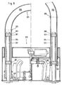
- a roll bar system shown which is a rigid with the vehicle connected housing cassette 320, in which all Elements for driving and locking the against the Housing cassette movable bracket tube 321 arranged are. Since the drive and the locking of the Roll bar is not the subject of the present Invention is, should not be discussed in detail become.
- the bow tube 321 consists of a semi-circular curved base 326, which the two straight leg 324 connects. This in parallel extending stirrup legs 324 are on the stanchions 322 pushed so that they the standpipes 322 and Surround guide bushings 301.
- the guide bushings 301 rest with their tongues 303 on the inner lateral surfaces the stirrup leg 324.
Landscapes
- Engineering & Computer Science (AREA)
- General Engineering & Computer Science (AREA)
- Mechanical Engineering (AREA)
- Springs (AREA)
Description
- Fig. 1
- einen Schnitt durch eine Ausführungsform einer erfindungsgemäßen Führungsbuchse,
- Fig. 2
- eine seitliche Draufsicht auf die Führungsbuchse nach Fig. 1,
- Fig. 3
- einen Teilschnitt entlang der Linie C-C in Fig. 1,
- Fig. 4
- eine Teildraufsicht auf eine zweite Ausführungsform einer erfindungsgemäßen Führungsbuchse,
- Fig. 5
- einen Teilschnitt durch die Führungsbuchse nach Fig. 4,
- Fig. 6
- eine Teildraufsicht auf eine dritte Ausführungsform einer erfindungsgemäßen Führungsbuchse,
- Fig. 7
- einen Teilschnitt durch eine Führungsbuchse nach Fig. 6
- Fig. 8
- einen Überrollbügel als Einbaubeispiel für eine erfindungsgemäße Führungsbuchse.
- 1
- Führungsbuchse
- 2
- mittlerer Axialabschnitt
- 3
- Zungen
- 4
- Schlitze
- 5
- Federdrähte
- 6
- Innenwölbung
- 7
- Außenwölbung
- 8
- Drahtenden
- 9
- Vorsprünge
- 101
- Führungsbuchse
- 108
- Drahtenden
- 109
- Vorsprünge
- 110
- Durchbruchkanten
- 201
- Führungsbuchse
- 208
- Drahtenden
- 210
- Durchbruchkanten
- 301
- Führungsbuchse
- 303
- Zungen
- 320
- Gehäusekassette
- 321
- Bügelrohr
- 322
- Standrohre
- 324
- Bügelschenkel
- 325
- Übergang
- 326
- Basisteil
- 327
- Schenkelende
Claims (8)
- Führungsbuchse (1, 101, 201, 301) aus Kunststoff zur spielfreien Abstützung und Axialführung eines zylindrischen Körpers in einem zylindrischen Hohlraum, beispielsweise eines Standrohres (322) in einem hohlen zylindrischen Bügelschenkel (324) eines geradlinig ausfahrbaren Überrollbügels (321) für Kraftfahrzeuge, mit einem Axialabschnitt (2), dessen Innenkontur der Außenkontur des Körpers angepaßt ist und an ihm entsprechend anliegt, und mit mehreren beidseitig an den Axialabschnitt (2) angeformten Zungen (3, 303), die radial nach außen gewölbt, und die federnd nach außen gerichtet und vorgespannt sind, dadurch gekennzeichnet, daßan jedem axialen Ende des Axialabschnittes (2) ein Satz Zungen (3, 303) angeformt ist, und die Zungen (3, 303) zur Anlage an der Hohlraum-Innenwand mit einer Außenwölbung (7) versehen sind, und daßjedem Satz Zungen ein Federelement in Form eines Drahtringes (5) zugeordnet ist, der jeweils am Umfang der radialen Innenseite der zugehörigen Zungen anliegt und diese radial nach außen elastisch vorspannt.
- Führungsbuchse nach Anspruch 1, dadurch gekennzeichnet, daß an beiden axialen Enden jeweils einen Satz von mindestens vier Zungen (3) angeordnet ist, deren Breite in Umfangsrichtung jeweils größer ist als der Abstand zu den benachbarten Zungen.
- Führungsbuchse nach Anspruch 1 oder 2, dadurch gekennzeichnet, daß ihr Querschnitt einen geschlossenen Ring bildet.
- Führungsbuchse nach Anspruch 1 oder 2, dadurch gekennzeichnet, daß ihr Querschnitt einen durchbrochenen Ring bildet, wobei die an den Durchbruch angrenzenden Zungen nicht als benachbart gelten.
- Führungsbuchse nach Anspruch 4, dadurch gekennzeichnet, daß der Durchbruch einen kleineren Winkelbereich (q) als 50° einnimmt.
- Führungsbuchse nach einem der Ansprüche 1 bis 5, dadurch gekennzeichnet, daß der Drahtring (5) durch einen durchbrochenen Ring aus Federstahldraht gebildet ist.
- Führungsbuchse nach Anspruch 6, dadurch gekennzeichnet, daß die Zungen (3), an denen sich die Enden (8, 108) des durchbrochenen Ringes (5) aus Federstahldraht befinden, radial nach innen weisende Vorsprünge (9, 109) aufweisen.
- Führungsbuchse nach Anspruch 4 oder 5, und 6 oder 7, dadurch gekennzeichnet, daß die Enden (208) des durchbrochenen Ringes (5) aus Federstahldraht an den Kanten (210) des Durchbruchs radial nach außen umgebogen sind.
Applications Claiming Priority (2)
| Application Number | Priority Date | Filing Date | Title |
|---|---|---|---|
| DE4342403 | 1993-12-13 | ||
| DE4342403A DE4342403C2 (de) | 1993-12-13 | 1993-12-13 | Führungsbuchse für einen Überrollbügel |
Publications (2)
| Publication Number | Publication Date |
|---|---|
| EP0657327A1 EP0657327A1 (de) | 1995-06-14 |
| EP0657327B1 true EP0657327B1 (de) | 2000-03-08 |
Family
ID=6504837
Family Applications (1)
| Application Number | Title | Priority Date | Filing Date |
|---|---|---|---|
| EP94119463A Expired - Lifetime EP0657327B1 (de) | 1993-12-13 | 1994-12-09 | Führungsbuchse für einen Überrollbügel |
Country Status (2)
| Country | Link |
|---|---|
| EP (1) | EP0657327B1 (de) |
| DE (2) | DE4342403C2 (de) |
Families Citing this family (8)
| Publication number | Priority date | Publication date | Assignee | Title |
|---|---|---|---|---|
| DE19604423A1 (de) * | 1996-02-07 | 1997-08-14 | Bayerische Motoren Werke Ag | Überrollschutz für ein Kraftfahrzeug |
| NO962574D0 (no) * | 1996-06-18 | 1996-06-18 | Raufoss Automotive As | Anordning ved velteböyle for et kjöretöy |
| DE19710095B4 (de) * | 1997-03-12 | 2011-02-03 | Ise Automotive Gmbh | Multifunktionsführungsring zur Radialkraftaufnahme und spiel- und reibungsfreier Axialführung zylindrischer Bauteile |
| EP1106848A1 (de) * | 1999-12-06 | 2001-06-13 | Straub Werke AG | Hülse |
| DE10040642C1 (de) * | 2000-08-19 | 2001-09-27 | Ise Gmbh | Überrollschutzsystem |
| DE102006001579B3 (de) * | 2006-01-12 | 2007-03-01 | Ise Innomotive Systems Europe Gmbh | Überrollschutzsystem für Kraftfahrzeuge mit einem aktiv aufstellbaren Überrollbügel |
| DE102009000626A1 (de) * | 2009-02-04 | 2010-08-19 | Alutech Gmbh | Überrollschutzsystem |
| JP2016056944A (ja) * | 2014-09-11 | 2016-04-21 | オイレス工業株式会社 | 軸受ブッシュ及びこの軸受ブッシュを備えたペダル装置 |
Family Cites Families (5)
| Publication number | Priority date | Publication date | Assignee | Title |
|---|---|---|---|---|
| IT7722358U1 (it) * | 1977-09-26 | 1979-03-26 | Spica Spa | Boccola flottante a recupero di gioco |
| US4208075A (en) * | 1978-09-25 | 1980-06-17 | Burroughs Corporation | Zero clearance linear bearing apparatus |
| FR2532700A1 (fr) * | 1982-09-03 | 1984-03-09 | Messier Hispano Sa | Palier pour arbre |
| DE4017778A1 (de) * | 1990-06-01 | 1991-12-05 | Bayerische Motoren Werke Ag | Antrieb fuer einen ueberrollbuegel eines kraftfahrzeuges |
| DE4108878C2 (de) * | 1991-03-19 | 2003-04-17 | Ise Gmbh | Antrieb für einen translatorisch ausfahrbaren Überrollbügel eines Kraftfahrzeuges |
-
1993
- 1993-12-13 DE DE4342403A patent/DE4342403C2/de not_active Expired - Fee Related
-
1994
- 1994-12-09 EP EP94119463A patent/EP0657327B1/de not_active Expired - Lifetime
- 1994-12-09 DE DE59409186T patent/DE59409186D1/de not_active Expired - Fee Related
Also Published As
| Publication number | Publication date |
|---|---|
| EP0657327A1 (de) | 1995-06-14 |
| DE59409186D1 (de) | 2000-04-13 |
| DE4342403C2 (de) | 2001-08-16 |
| DE4342403A1 (de) | 1995-06-14 |
Similar Documents
| Publication | Publication Date | Title |
|---|---|---|
| DE3841629C2 (de) | Rollenlagerung | |
| EP1233205A2 (de) | Federungsanordnung | |
| DE2751342A1 (de) | Radaggregat | |
| DE2451084B2 (de) | Kugelgelenk | |
| DE3426607C2 (de) | ||
| EP1573231B1 (de) | Kugelgewindetrieb | |
| DE4342403C2 (de) | Führungsbuchse für einen Überrollbügel | |
| DE3403259C1 (de) | Fensterhebergetriebe | |
| DE4104032C1 (de) | ||
| DE102008009815B4 (de) | Rückzugkugel für eine hydrostatische Kolbenmaschine und System aus einer solchen Rückzugskugel und aus einer Vielzahl von Federn | |
| DE8808443U1 (de) | Kugelgelenk | |
| DD141340A5 (de) | Kugelbuchse fuer laengskugelfuehrungen | |
| EP0004593B1 (de) | Kugelbüchse für Linearbewegungen | |
| DE112019004166T5 (de) | Zahnstangen-Lenkgetriebeeinheit | |
| EP0916556A2 (de) | Rollenumlenkung | |
| DE3149944A1 (de) | Elektrischer schalter, insbesondere fuer kraftfahrzeuge | |
| DE935520C (de) | Gleitlager | |
| DE102010029137B4 (de) | Gelenkanordnung, insbesondere Traggelenk | |
| DE102019107684A1 (de) | Kugelgewindetrieb | |
| DE102008016798A1 (de) | Wälzlager sowie Lenkgetriebe mit einem derartigen Wälzlager | |
| DE3045391C2 (de) | ||
| DE112022006783T5 (de) | Lenkvorrichtung für ein fahrzeug | |
| EP1532043B1 (de) | Verschiebelager und motorradgabel mit einem solchen verschiebelager | |
| DE10339563B4 (de) | Gurtumlenker mit einem Verdrängungskörper | |
| DE102024127842B3 (de) | Lenksäule für ein Kraftfahrzeug |
Legal Events
| Date | Code | Title | Description |
|---|---|---|---|
| PUAI | Public reference made under article 153(3) epc to a published international application that has entered the european phase |
Free format text: ORIGINAL CODE: 0009012 |
|
| 17P | Request for examination filed |
Effective date: 19941209 |
|
| AK | Designated contracting states |
Kind code of ref document: A1 Designated state(s): DE FR GB IT |
|
| 17Q | First examination report despatched |
Effective date: 19961011 |
|
| GRAG | Despatch of communication of intention to grant |
Free format text: ORIGINAL CODE: EPIDOS AGRA |
|
| GRAG | Despatch of communication of intention to grant |
Free format text: ORIGINAL CODE: EPIDOS AGRA |
|
| GRAH | Despatch of communication of intention to grant a patent |
Free format text: ORIGINAL CODE: EPIDOS IGRA |
|
| GRAH | Despatch of communication of intention to grant a patent |
Free format text: ORIGINAL CODE: EPIDOS IGRA |
|
| RAP1 | Party data changed (applicant data changed or rights of an application transferred) |
Owner name: ISE INNOMOTIVE SYSTEMS EUROPE GMBH |
|
| GRAA | (expected) grant |
Free format text: ORIGINAL CODE: 0009210 |
|
| AK | Designated contracting states |
Kind code of ref document: B1 Designated state(s): DE FR GB IT |
|
| REF | Corresponds to: |
Ref document number: 59409186 Country of ref document: DE Date of ref document: 20000413 |
|
| ITF | It: translation for a ep patent filed | ||
| GBT | Gb: translation of ep patent filed (gb section 77(6)(a)/1977) |
Effective date: 20000526 |
|
| ET | Fr: translation filed | ||
| PLBE | No opposition filed within time limit |
Free format text: ORIGINAL CODE: 0009261 |
|
| STAA | Information on the status of an ep patent application or granted ep patent |
Free format text: STATUS: NO OPPOSITION FILED WITHIN TIME LIMIT |
|
| 26N | No opposition filed | ||
| REG | Reference to a national code |
Ref country code: GB Ref legal event code: IF02 |
|
| PGFP | Annual fee paid to national office [announced via postgrant information from national office to epo] |
Ref country code: DE Payment date: 20041211 Year of fee payment: 11 |
|
| PG25 | Lapsed in a contracting state [announced via postgrant information from national office to epo] |
Ref country code: DE Free format text: LAPSE BECAUSE OF NON-PAYMENT OF DUE FEES Effective date: 20060701 |
|
| PGFP | Annual fee paid to national office [announced via postgrant information from national office to epo] |
Ref country code: IT Payment date: 20071224 Year of fee payment: 14 |
|
| PGFP | Annual fee paid to national office [announced via postgrant information from national office to epo] |
Ref country code: GB Payment date: 20071220 Year of fee payment: 14 |
|
| PGFP | Annual fee paid to national office [announced via postgrant information from national office to epo] |
Ref country code: FR Payment date: 20071214 Year of fee payment: 14 |
|
| GBPC | Gb: european patent ceased through non-payment of renewal fee |
Effective date: 20081209 |
|
| REG | Reference to a national code |
Ref country code: FR Ref legal event code: ST Effective date: 20090831 |
|
| PG25 | Lapsed in a contracting state [announced via postgrant information from national office to epo] |
Ref country code: GB Free format text: LAPSE BECAUSE OF NON-PAYMENT OF DUE FEES Effective date: 20081209 |
|
| PG25 | Lapsed in a contracting state [announced via postgrant information from national office to epo] |
Ref country code: FR Free format text: LAPSE BECAUSE OF NON-PAYMENT OF DUE FEES Effective date: 20081231 |
|
| PG25 | Lapsed in a contracting state [announced via postgrant information from national office to epo] |
Ref country code: IT Free format text: LAPSE BECAUSE OF NON-PAYMENT OF DUE FEES Effective date: 20081209 |