EP0657294A2 - Automatic platen gap adjusting device for printer - Google Patents
Automatic platen gap adjusting device for printer Download PDFInfo
- Publication number
- EP0657294A2 EP0657294A2 EP94119538A EP94119538A EP0657294A2 EP 0657294 A2 EP0657294 A2 EP 0657294A2 EP 94119538 A EP94119538 A EP 94119538A EP 94119538 A EP94119538 A EP 94119538A EP 0657294 A2 EP0657294 A2 EP 0657294A2
- Authority
- EP
- European Patent Office
- Prior art keywords
- carriage
- platen
- recording sheet
- printer
- load
- Prior art date
- Legal status (The legal status is an assumption and is not a legal conclusion. Google has not performed a legal analysis and makes no representation as to the accuracy of the status listed.)
- Granted
Links
- 238000001514 detection method Methods 0.000 claims abstract description 30
- 238000000034 method Methods 0.000 claims description 3
- 230000000694 effects Effects 0.000 description 8
- 238000010586 diagram Methods 0.000 description 5
- 230000010354 integration Effects 0.000 description 3
- 238000010186 staining Methods 0.000 description 2
- 230000005540 biological transmission Effects 0.000 description 1
- 238000010276 construction Methods 0.000 description 1
- 230000007423 decrease Effects 0.000 description 1
- 230000003247 decreasing effect Effects 0.000 description 1
- 230000002950 deficient Effects 0.000 description 1
- 230000001419 dependent effect Effects 0.000 description 1
- 230000005284 excitation Effects 0.000 description 1
- 238000007689 inspection Methods 0.000 description 1
Images


Classifications
-
- B—PERFORMING OPERATIONS; TRANSPORTING
- B41—PRINTING; LINING MACHINES; TYPEWRITERS; STAMPS
- B41J—TYPEWRITERS; SELECTIVE PRINTING MECHANISMS, i.e. MECHANISMS PRINTING OTHERWISE THAN FROM A FORME; CORRECTION OF TYPOGRAPHICAL ERRORS
- B41J25/00—Actions or mechanisms not otherwise provided for
- B41J25/304—Bodily-movable mechanisms for print heads or carriages movable towards or from paper surface
- B41J25/308—Bodily-movable mechanisms for print heads or carriages movable towards or from paper surface with print gap adjustment mechanisms
- B41J25/3082—Bodily-movable mechanisms for print heads or carriages movable towards or from paper surface with print gap adjustment mechanisms with print gap adjustment means on the print head carriage, e.g. for rotation around a guide bar or using a rotatable eccentric bearing
-
- B—PERFORMING OPERATIONS; TRANSPORTING
- B41—PRINTING; LINING MACHINES; TYPEWRITERS; STAMPS
- B41J—TYPEWRITERS; SELECTIVE PRINTING MECHANISMS, i.e. MECHANISMS PRINTING OTHERWISE THAN FROM A FORME; CORRECTION OF TYPOGRAPHICAL ERRORS
- B41J25/00—Actions or mechanisms not otherwise provided for
- B41J25/304—Bodily-movable mechanisms for print heads or carriages movable towards or from paper surface
- B41J25/308—Bodily-movable mechanisms for print heads or carriages movable towards or from paper surface with print gap adjustment mechanisms
Abstract
Description
- This invention relates to devices for automatically adjusting a gap between a platen and a recording head in accordance with the thickness of a recording sheet.
- In a recording head, and particularly a wire dot type recording head that prints data by impinging wires onto a recording sheet through an ink ribbon, a wire impinging speed must be minimized in order to achieve high speed printing.
- Since the wire dot type recording head is mechanically rigid and capable of copying data through a copying material, the recording head can be used with a wide variety of different types of sheets. This feature is problematic, however, because the distance between the recording head and the recording sheet varies by a greater degree than in printers of other types.
- To overcome this problem, a printer especially a wire dot type printer, usually has a mechanism for adjusting a relative gap length between the platen and the recording head. However, the user must be well skilled in selecting the optimal gap for each kind of sheet used, and the selecting operation is cumbersome.
- The printer disclosed in Japanese Examined Patent Publication No. 4-14634 is intended to overcome the above noted problems. This printer has an encoder that generates pulse signals in association with the movement of the carriage from an initial position thereof, and a control section that processes a feedback pulse signal from the encoder. The first instance of a carriage driving pulse motor losing synchronism is detected from a change in the number of pulses from the encoder due to an abutment of the recording head against a recording sheet, and the thickness of the recording sheet is calculated based on the amount of movement of the carriage up to the moment of abutment, so that the position of the carriage can be controlled based on the recording sheet thickness data.
- Although the platen gap is adjusted as described above, unsatisfactory contact between the recording sheet and the platen causes the recording head and/or an ink ribbon to come in contact with the recording sheet, possibly causing problems such as breakage and staining of the recording head.
- The invention has been made in consideration of the aforementioned problems, and the object of the invention is, therefore, to provide an automatic platen gap adjusting device capable of preventing the recording head from being broken or stained.
- This object is solved by the automatic platen gap adjusting device of any one of
independent claims claim 13. In particular, the invention is directed to devices for adjusting the gap to an optimal value by judging the thickness of a loaded recording sheet. This invention, as per a preferred aspect, achieves the above object by not only measuring the thickness of a recording sheet by causing the carriage to come in pressure contact with the recording sheet with a sufficiently small force, but also by automatically judging the gap between the recording head and the recording sheet. - Further advantageous features, aspects and details of the invention are evident from the dependent claims, the description and the drawings. The claims are intended to be understood as a first non-limiting approach of defining the invention in general terms.
- To achieve the above objects, the invention, according to a specific aspect, is applied to an automatic platen gap adjusting device for a printer, which includes: a carriage motor for driving a carriage in parallel with a platen shaft, the carriage carrying a recording head; a means for detecting a load from a load current of the carriage motor when the carriage is moved in parallel with the platen shaft at a predetermined speed; an initial load storage means for storing the load at the time a recording sheet is not loaded as an initial load; a contact judgment means for comparing the load at the time the recording sheet is loaded with the initial load and judging that the recording head is in contact with the recording sheet when a difference between both loads exceeds a reference value; means for moving the carriage in direction which contains at least a component orthogonal to the platen shaft whereby said means are preferably provided by a stepper motor; a movement amount detection means for generating a number of pulse signals proportional to an amount of movement of the carriage in the direction orthogonal to the platen shaft; an abutment judgment means for moving the carriage toward a platen from a reference position, integrating time differences between respective drive pulses of the moving means especially the stepper motor and corresponding pulse signals generated from the movement amount detection as a result of the drive of moving means (e.g. the stepper motor) by the drive pulses, and judging that the integrated value of the time differences has reached a predetermined value. The platen gap adjusting device advantageously may further comprise a sheet thickness calculation means for calculating a thickness of a recording sheet based on the amount of movement of the carriage from the reference position upon output of a signal from the abutment judgment means, and optionally a control means for adjusting a relative gap length between the carriage and the platen by driving the moving means (e.g., the stepper motor) based on data from the sheet thickness calculation means.
- While counting the amount of movement of the carriage toward the platen from the reference position, a time difference between the moving means (e.g., the stepper motor) drive pulse and the pulse signal from the movement detection means is detected. When the integrated value of the time differences has reached a preset value and at a stage before losing synchronism, abutment of the recording head against the recording sheet is judged, and the thickness of the recording sheet is determined or calculated from the amount of movement of the carriage up to the moment of abutment. As a result of this, the relative gap length between the platen and the carriage is set to an optimal value.
- Next, a load applied to the carriage motor and a load with no recording sheet loaded can be compared with each other by moving the carriage in the main scanning direction after the platen gap has been adjusted in order to check that the recording head is not in contact with the recording sheet.
- Preferred embodiments of the invention are described in detail below with reference to the accompanying drawings, in which:
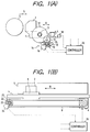
- Figure 1(A) is an end view and diagram of an embodiment of a carriage drive mechanism of a serial printer to which the invention is applied;
- Figure 1(B) is view orthogonal to the end view of the embodiment in Figure 1(A) of another feature of the carriage drive mechanism shown in Figure 1(A);
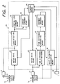
- Figure 2 is a diagram showing a configuration of an embodiment of the invention;
- Figure 3 is a flowchart showing a mode of operation of the embodiment shown in Figure 2;
- Figure 4 is a waveform diagram showing the mode of operation of the embodiment shown in Figure 2;
- Figure 5 is a diagram showing a change in the integrated value of time differences when the recording head starts being abutted against a recording sheet; and
- Figure 6 is an end view and diagram of another embodiment of the invention.
- Figures 1(A) and 1(B) are different views of an embodiment of a mechanism for adjusting a relative gap length between the platen and the recording head of a serial printer to which the invention can be applied. In these figures,
reference numeral 1 denotes a carriage having an impact wiretype recording head 2 carried thereon and being disposed on aguide shaft 3 and afixed guide shaft 4. Theguide shaft 3 is mounted on a base so as to be eccentrically rotatable. Thecarriage 1 can move in directions indicated by the double ended arrow "A" in Figure 1 (A). As a result of this construction, a relative gap length "G" of therecording head 2 with respect to theplaten 5 can be adjusted by the amount of rotation of theguide shaft 3. Thecarriage 1 is connected to acarriage motor 6, e.g., a dc motor, through atiming belt 9, so that thecarriage 1 can shuttle in directions of the platen shaft indicated by the double ended arrow "B" in Figure 1(B) with the gap length "G" adjusted by theguide shaft 3. -
Reference numeral 10 denotes a stepper motor that rotates theguide shaft 3. Thisstepper motor 10 drives theguide shaft 3 by 2-2 phase excitation and at a cycle of 3.5 ms, and is connected to a drivenwheel 12 of theguide shaft 3 through areduction gear 11. Ashaft 13 of thestepper motor 10 carries acode disk 15 of afirst encoder 14 that generates a pulse signal indicating a value proportional to the angle of rotation thereof. The code pattern of thecode disk 15 is such that a single pulse width signal can be generated from acode detector 16 in synchronism with single phase drive of thestepper motor 10.Reference numeral 18 denotes a position detection means that is positioned so as to output a signal when thecarriage 1 has reached a reference position at which thecarriage 1 is farthest from theplaten 5. A microswitch may be used as the position detection means in one preferred embodiment. - A
second encoder 25 is provided to measure movement of thecarriage 1 in the main scanning direction. Thesecond encoder 25 comprises acode disk 22 fixed on anidler 20 of thetiming belt 9 and acode detector 24 that detects a code indicated by the code disk. -
Reference numeral 26 denotes a controller, which receives signals from the first andsecond encoders position detector 18, and controls thecarriage motor 6 and thestepper motor 10. - Figure 2 shows an embodiment of the
controller 26. In Figure 2,reference numeral 30 denotes a motor drive means for driving themotor 6 that moves thecarriage 1 in the main scanning direction. The motor drive means 30 is activated by a signal from a control means 46, which judges thecarriage 1 moving speed from a signal from thesecond encoder 25, and adjusts the duty of a current pulse to be supplied to thecarriage motor 6 so that thecarriage 1 moving speed becomes constant. -
Reference numeral 31 denotes a load detection means, which detects a load applied to thecarriage motor 6 based on the duty of the current pulse supplied to thecarriage motor 6, and delivers the detected value to an initial load storage means 32 when no recording sheet is loaded. Reference numeral 33 denotes a contact judgment means, which calculates a difference between a signal from the load detection means 31 when the recording sheet is loaded and the value of the initial load storage means 32, compares the difference with a reference value, and judges whether therecording head 2 is in contact with the recording sheet when the difference exceeds the reference value. -
Reference numeral 40 denotes a motor drive means, which drives thestepper motor 10 to move thecarriage 1 in the direction orthogonal to theplaten 5.Reference numeral 41 denotes a time difference detection means, which judges whether a time difference between the cycle of a pulse signal from thefirst encoder 14 and the cycle of a drive signal of thestepper motor 10 changes, and outputs an amount of change ΔTn in the time difference when the time difference has changed.Reference numeral 42 denotes a time difference integration means, which calculates an integrated value Σ (ΔTn) of the amounts of change ΔTn in the time difference, and outputs the integrated value Σ to an abutment judgment means 43, which will be described below. -
Reference numeral 43 denotes the abutment judgment means, which outputs a signal upon coincidence of the integrated value of the amounts of change in the time difference from the time difference integration means 43 with a reference value. The reference value in this embodiment is a value half or less of the cycle of the drive pulse of thestepper motor 10, e.g., 1.5 ms. -
Reference numeral 44 denotes a sheet thickness calculation means, which counts the number of pulse signals from theencoder 14 based on a signal from theposition detector 18, stops counting in accordance with a signal from the abutment judgment means 43, and calculates the thickness of a recording sheet based on the pulse signal count. -
Reference numeral 46 denotes the control means, which not only controls thestepper motor 10 for adjusting the platen gap, but also effects a sequence control for checking that the recording sheet is not in contact with therecording head 2 after the platen gap has been adjusted. Specifically, the control means 46 drives thecarriage motor 6 with no recording sheet being loaded, e.g., at the time a power switch is not turned on; sets thecarriage 1 to the reference position thereof by causing thecarriage 1 to retreat in such a direction as to move away from theplaten 5 until a signal is outputted from theposition detector 18 upon pressing of a loading switch (not shown); causes thecarriage 1 to move toward theplaten 5 to thereby cause therecording head 2 to be abutted against the recording sheet; drives thestepper motor 10 so that an optimal gap length is given to the loaded recording sheet after the thickness of the recording sheet has been detected; and finally drives thecarriage motor 6 again after the platen gap has been adjusted. - A mode of operation of the thus constructed device will be described next with reference to a flowchart shown in Figure 3.
- When a power switch (not shown) of a printer has been turned on (Step 1), the control means 46 drives the
carriage motor 6 to cause thecarriage 1 to move along the platen 5 (Step 2). When thecarriage 1 has reached a predetermined constant speed (Step 3), the load detection means 31 detects a load of thecarriage motor 6 from the duty of a current pulse supplied to thecarriage motor 6, and stores in the initial load storage means 32 the detected load as a reference load of the carriage at the time therecording head 2 is not in contact with the recording sheet (Step 4). - When the loading switch is pressed to load the recording sheet (Step 5), the recording sheet is set on the
platen 5 by a loading mechanism (not shown) (Step 6). Then, the control means 46 instructs the motor drive means 30 to move thecarriage 1 to substantially the center of the print region (Step 7) and temporarily drives thestepper motor 5 reversely to cause thecarriage 1 to retreat in such a direction as to be opposite to theplaten 5, i.e., toward theposition detector 18. When thecarriage 1 has reached the reference position as a result of this control, a signal is generated from theposition detector 18, which causes the control means 46 to stop the stepper motor 10 (Step 8). - Then, the control means 46 forwardly drives the
stepper motor 10 at a predetermined rotational speed to move thecarriage 1 toward theplaten 5 and, at the same time, counts the number of pulse signals from thefirst encoder 14. After thecarriage 1 has made a movement equivalent to a predetermined number of pulses, the time difference detection means 41 judges whether a time difference is present between the drive pulse cycle of thestepper motor 10 and the pulse signal cycle of therotary encoder 14. Since the load applied to thestepper motor 10 remains constant until therecording head 2 is abutted against the recording sheet, there is no time difference between the cycle of each pulse signal from therotary encoder 14 and the drive pulse cycle of thestepper motor 10 during this period and, therefore, the integrated value thereof remains equal to zero (Figure 4) (Step 9). - As the
carriage 1 further moves toward theplaten 5, therecording head 2 starts to abut against the recording sheet, which in turn decreases the rotational speed of thefirst encoder 14 because the load is applied to thecarriage 1. As a result, the cycle of each pulse signal from theencoder 14 is increased to cause an amount of change ΔT to the time difference T with respect to the drive signal of thestepper motor 10. The time difference integration means 42 sequentially integrates such amounts of change ΔT in the time difference and delivers the integrated value to the abutment judgment means 43. The load of thestepper motor 10 increases with increasing distance of movement of thecarriage 1 toward the platen 5 (Figure 5), causing the integrated value Σ (ΔT) of the amounts of change ΔTn in the time difference to increase so drastically as to reach the preset value (Step 10). Accordingly, the abutment judgment means 43 judges that therecording head 2 has been abutted against the recording sheet and thereby generates a signal that indicates the abutment. - The control means 46 stops the rotation of the
stepper motor 10 upon reception of the signal from the abutment judgment means 43, whereas the sheet thickness calculation means 44 calculates the thickness of the recording sheet by stopping the counting of pulses from thefirst encoder 14 based on the signal from the abutment judgment means 43 (Step 11). The control means 46 causes thecarriage 1 to retreat from theplaten 5 and fixes thecarriage 1 at an optimal position by driving thestepper motor 10 based on the calculated sheet thickness so that an optimal gap length can be given to the recording sheet (Step 12). - After the adjustment of the platen gap, the control means 46 causes the
carriage 1 to move in parallel with theplaten 5 by driving thecarriage motor 6 again (Step 13). When thecarriage 1 has reached the constant speed (Step 14), the load detection means 31 detects a load required for driving thecarriage 1 based on the duty of a current pulse that drives the carriage motor 6 (Step 15). The contact judgment means 33 calculates a difference between a currently detected load and the load stored in the initial load storage means 32 (Step 16). If the calculated difference is smaller than the reference value (Step 16), then the printer, being ready to print, is set to a stand-by mode. - On the other hand, if the calculated difference is larger than the reference value (Step 17), then the control means 46, recognizing that the
carriage 1 has a high travel resistance due to therecording head 2 and the ink ribbon being in contact with the recording sheet, increases the platen gap by applying a drive pulse to thestepper motor 10 so that thecarriage 1 makes a retreat equivalent to a predetermined distance, e.g., a single step, from the platen 5 (Step 18). The control means 46 then drives thecarriage motor 6 again to move thecarriage 1 along the length of the shaft of the platen 5 (Step 19). Then, when thecarriage 1 has reached the constant speed (Step 20), the load of thecarriage motor 6 is detected (Step 21) and a difference between the detected load and the load in the initial load storage means 32 is calculated (Step 21). If the difference is smaller than the reference value (Step 22), the printer is set to the stand-by mode with the adjusted platen gap and waits for a print data input. On the other hand, if the load has not decreased in spite of the platen gap readjustment (Step 22), then the control means 46 ejects the recording sheet by judging the recording sheet loading as being erroneous (Step 23), and gives an alarm to the user for inspection as necessary. - Although the load of the carriage motor is measured every time a load is applied to the carriage motor in the aforementioned embodiment, a similar effect can be obtained by storing a load as a fixed value.
- Further, although the reference position detection means 18 is arranged to set the reference position in the aforementioned embodiment, it is apparent that a similar effect can be obtained by measuring the distance between an arbitrary carriage position and the platen surface by the carriage to retreat to the original position, and then calculating the distance by which the carriage is abutted against the recording sheet after loading the recording sheet onto the platen.
- It is also apparent that a similar effect can be obtained by arranging, as shown in Figure 6, a means for driving the
carriage 1, e.g., apositioning projection 12a on the drivenwheel 12, and apositioning pin 50 on the stationary side and causing these means to mechanically set the reference. - It is further apparent that while the amount of movement of the
carriage 1 toward the platen and the speed of the carriage are detected by the rotary encoders in this embodiment, a similar effect can be obtained by using a linear detector such as a magnet scale that converts a linear distance into a number of pulses. - It is still further apparent that while this embodiment is designed to synchronize the drive signal of the carriage driving stepper motor with the pulse signal of the
rotary encoder 14, a similar effect can be obtained by judging the movement of the carriage from the number of drive pulses within the cycle of the pulse signal of therotary encoder 14 if the cycle of the drive signal is significantly smaller than the cycle of the pulse signal of therotary encoder 14. - It is still further apparent that while the dedicated stepper motor is arranged to move the carriage in the direction orthogonal to the platen shaft in the aforementioned embodiment, a similar effect can be obtained by selectively connecting the carriage motor through a transmission mechanism.
- It is still further apparent that while the dc motor is used to drive the carriage in the aforementioned embodiment, a similar effect can be obtained by using a pulse motor.
- As described in the foregoing, the invention may preferably include : a means for detecting a load from a load current of a carriage motor when a carriage is moved in parallel with a platen shaft at a predetermined speed; an initial load storage means for storing a load at the time a recording sheet is not loaded as an initial load; a contact judgment means for comparing a load at the time the recording sheet is loaded with the initial load, and judging that the recording head is in contact with the recording sheet when a difference between both loads exceeds a reference value; a stepper motor for moving the carriage in a direction orthogonal to the platen shaft; a movement amount detection means for generating a number of pulse signals proportional to an amount of movement of the carriage in the direction orthogonal to the platen shaft; an abutment judgment means for moving the carriage toward the platen from a reference position, integrating time differences between respective drive pulses of the stepper motor and corresponding pulse signals generated from the movement amount detection means as a result of the drive of the stepper motor by the drive pulses, and thereby judging that the integrated value of the time differences has reached a predetermined value; a sheet thickness calculation means for calculating the thickness of a recording sheet based on the amount of movement of the carriage from the reference position upon output of a signal from the abutment judgment means; and a control means for adjusting a relative gap length between the carriage and the platen by driving the stepper motor based on data of the sheet thickness calculation means. Therefore, the platen gap can be set to an optimal value by judging the time upon which the recording head has been abutted against the recording sheet without applying an unnecessarily large force to the recording sheet. Moreover, breakage and staining of the recording head due to defective loading of a recording sheet can be prevented by checking whether there is contact between the recording head and the recording sheet after the platen gap has been set.
Claims (13)
- A platen gap adjusting device for a printer, comprising:
carriage driving means (6,9) for driving a carriage (1) in parallel with a platen shaft, the carriage (1) carrying a recording head (2);
means (31) for detecting a load of the carriage driving means (6,9) when the carriage (1) is moved in parallel with the platen shaft at a predetermined speed;
initial load storage means (32) for storing an initial load before a recording sheet is inserted in the printer;
contact judgment means (33) for judging whether or not the recording head (2) is in contact with the recording sheet based on a comparison between a load at the time the recording sheet is inserted in the printer and the initial load; and
moving means (3,10,11,12) for moving the carriage in a direction orthogonal to the platen shaft based on the judgment of the contact judgment means (33). - An automatic platen gap adjusting device for a printer according to claim 1, comprising:
a carriage motor (6) for driving a carriage (1) in parallel with a platen shaft, the carriage (1) carrying a recording head (2);
means (31) for detecting a load from a load current of the carriage motor when the carriage (1) is moved in parallel with the platen shaft at a predetermined speed;
initial load storage means (32) for storing an initial load before a recording sheet is inserted in the printer;
contact judgement means (33) for comparing a load at the time the recording sheet is inserted in the printer with the initial load and for judging whether or not the recording head (2) is in contact with the recording sheet when a difference between these loads exceeds a reference value;
moving means (3,10,11,12) especially a stepper motor (10) for moving the carriage in a direction orthogonal to the platen shaft;
movement amount detection means (14, 15) for generating a number of pulse signals proportional to an amount of movement of the carriage (1) in the direction orthogonal to the platen shaft;
abutment judgment means (43) for integrating time differences between respective drive pulses of the stepper motor (10) and corresponding pulse signals generated from the movement amount detection means (14, 15) as a result of the drive of the stepper motor (10) by the drive pulses, and for judging whether or not the integrated value of the time differences has reached a predetermined value;
sheet thickness calculation means (44) for calculating a thickness of the recording sheet based on the amount of movement of the carriage (1) from a reference position upon output of a signal from the abutment judgment means (43) indicating that the integrated value of the time differences has reached the predetermined value; and
control means (46) for adjusting a relative gap length between the carriage (1) and the platen (5) by driving the stepper motor (10) based on data from the sheet thickness calculation means (44). - The automatic platen gap adjusting device for a printer according to claim 2, wherein said control means (46) comprises means (40) for causing the carriage to retreat from the platen by driving the stepper motor (10) by a predetermined amount upon detection of contact between the recording head (2) and the recording sheet by the contact judgment means (33).
- An automatic platen gap adjusting device for a printer, especially according to one of the preceding claims, the printer comprising a carriage motor (6) for driving a carriage (1) in parallel with a platen shaft, the carriage (1) carrying a recording head (2), and a gap adjusting motor (10) for adjusting a relative gap length between the carriage (1) and a platen (5) by moving the carriage (1) in a direction orthogonal to the platen shaft, wherein the automatic platen gap adjusting device comprises:
means (31) for detecting a load applied to the carriage motor (6) when the carriage (1) is moved in parallel with the platen shaft at a predetermined speed;
initial load storage means (32) for storing an initial load before a recording sheet is inserted into printer;
contact judgment means (33) for comparing a load at the time the recording sheet is inserted in the printer with the initial load and for judging whether or not the recording head is in contact with the recording sheet when a difference between these loads exceeds a reference value; and
control means (46) for causing the carriage (1) to retreat from the platen (5) by driving the gap adjusting motor (10) by a predetermined amount upon detection of contact between the recording head (2) and the recording sheet by the contact judgment means (33). - The automatic platen gap adjusting device as recited in one of claims 2 to 4, wherein said movement amount detection means (14,15) comprises a rotary encoder (14).
- The automatic platen gap adjusting device as recited in one of claims 2 to 4, wherein said movement amount detection means (14,15) comprises a linear encoder.
- An automatic platen gap adjusting device for a printer, especially according to one of the preceding claims comprising:
a carriage motor (6) for driving a carriage (1) in parallel with a platen shaft, the carriage (1) carrying a recording head (2);
means (31) for detecting a load from a load current of the carriage motor (6) when the carriage (1) is moved in parallel with the platen shaft at a predetermined speed;
initial load storage means (32) for storing an initial load before a recording sheet is inserted in the printer;
contact judgment means (33) for comparing a load at the time the recording sheet is inserted in the printer with the initial load and for judging whether or not the recording head (2) is in contact with the recording sheet when a difference between these loads exceeds a reference value;
moving means (3,10,11,12) especially a stepper motor (10) for moving the carriage (1) in a direction orthogonal to the platen shaft;
movement amount detection means (14, 15) for generating a number of pulse signals proportional to an amount of movement of the carriage (1) in the direction orthogonal to the platen shaft;
abutment judgment means (43) for judging when the carriage (1) first contacts one of the platen (5) and/or the recording sheet by determining whether a number of drive pulses of the stepper motor within a cycle of the pulse signals of the movement amount detection means (14,15) has reached a predetermined value;
sheet thickness calculation means (44) for calculating a thickness of the recording sheet based on the amount of movement of the carriage (1) from a reference position upon output of a signal from the abutment judgment means (43) indicating that the predetermined value has been reached; and
control means (46) for adjusting a relative gap length between the carriage (1) and the platen (5) by driving the stepper motor (10) based on data from the sheet thickness calculation means (44). - An automatic platen gap adjusting device for a printer, the printer comprising a carriage motor (6) for driving a carriage (1) in parallel with a platen shaft, the carriage (1) carrying a recording head (2), and a gap adjusting motor (10) for adjusting a relative gap length between the carriage (1) and a platen (5) by moving the carriage (1) in a direction orthogonal to the platen shaft, wherein the automatic platen gap adjusting device comprises:
movement amount detection means (14,15) for generating a number of pulse signals proportional to an amount of movement of the carriage (1) in the direction orthogonal to the platen shaft;
abutment judgment means (43) for integrating time differences between respective drive pulses of the gap adjusting motor and corresponding pulse signals generated from the movement amount detection means (14,15) as a result of the drive of the gap adjusting motor by the drive pulses, and for judging whether or not the integrated value of the time differences has reached a predetermined value;
sheet thickness calculation means (44) for calculating a thickness of the recording sheet based on the amount of movement of the carriage (1) from a reference position upon output of a signal from the abutment judgment means (43) indicating that the integrated value of the time differences has reached the predetermined value; and
control means (46) for adjusting a relative gap length between the carriage (1) and the platen (5) by driving the gap adjusting motor (10) based on data from the sheet thickness calculation means (44). - An automatic platen gap adjusting device for a printer, the printer comprising a carriage motor (6) for driving a carriage (1) in parallel with a platen shaft, the carriage (1) carrying a recording head (2), and a gap adjusting motor (10) for adjusting a relative gap length between the carriage (1) and a platen (5) by moving the carriage (1) in a direction orthogonal to the platen shaft, wherein the automatic platen gap adjusting device comprises:
movement amount detection means (14,15) for generating a number of pulse signals proportional to an amount of movement of the carriage (1) in the direction orthogonal to the platen shaft;
abutment judgment means (43) for judging when the carriage (1) first contacts one of the platen (5) and/or the recording sheet by determining whether a number of drive pulses of the gap adjusting motor (10) within a cycle of the pulse signals of the movement amount detection means (14,15) has reached a predetermined value;
sheet thickness calculation means (44) for calculating a thickness of the recording sheet based on the amount of movement of the carriage (1) from a reference position upon output of a signal from the abutment judgment means (43) indicating that the predetermined value has been reached; and
control means (46) for adjusting a relative gap length between the carriage and the platen by driving the gap adjusting motor based on data from the sheet thickness calculation means. - An automatic platen gap adjusting device as recited in one of the preceding claims, further comprising position detection means (18,12a,50) for setting the reference position of the carriage (1).
- An automatic platen gap adjusting device as recited in claim 11, wherein said position detection means (18) comprises a microswitch.
- An automatic platen gap adjusting device as recited in claim 10, wherein said position detection means (12a,50) comprises a moving positioning projection (12a) associated with said carriage (1), said moving positioning projection (12a) contacting a stationary positioning pin (50) at the reference position.
- A method for adjusting a platen gap in a printer comprising:
driving a carriage carrying a recording head in parallel with a platen shaft;
detecting a load when the carriage is driven parallel with the platen shaft at a predetermined speed;
storing an initial load before a recording sheet is inserted in the printer;
judging whether or not the recording head is in contact with the recording sheet by comparing a load at the time the recording sheet is inserted in the printer with the initial load; and
moving the carriage in a direction orthogonal to the platen shaft on the basis of the judging step.
Applications Claiming Priority (3)
| Application Number | Priority Date | Filing Date | Title |
|---|---|---|---|
| JP341311/93 | 1993-12-09 | ||
| JP34131193 | 1993-12-09 | ||
| JP5341311A JP3019129B2 (en) | 1993-12-09 | 1993-12-09 | Automatic platen gap adjustment device for printer |
Publications (3)
| Publication Number | Publication Date |
|---|---|
| EP0657294A2 true EP0657294A2 (en) | 1995-06-14 |
| EP0657294A3 EP0657294A3 (en) | 1996-10-30 |
| EP0657294B1 EP0657294B1 (en) | 2000-03-22 |
Family
ID=18345077
Family Applications (1)
| Application Number | Title | Priority Date | Filing Date |
|---|---|---|---|
| EP94119538A Expired - Lifetime EP0657294B1 (en) | 1993-12-09 | 1994-12-09 | Automatic platen gap adjusting device for printer |
Country Status (5)
| Country | Link |
|---|---|
| US (1) | US5476328A (en) |
| EP (1) | EP0657294B1 (en) |
| JP (1) | JP3019129B2 (en) |
| DE (1) | DE69423578T2 (en) |
| SG (1) | SG54206A1 (en) |
Cited By (1)
| Publication number | Priority date | Publication date | Assignee | Title |
|---|---|---|---|---|
| EP0811504A1 (en) * | 1996-06-06 | 1997-12-10 | Seiko Epson Corporation | Automatic adjusting device for adjusting platen gap |
Families Citing this family (6)
| Publication number | Priority date | Publication date | Assignee | Title |
|---|---|---|---|---|
| US5713674A (en) * | 1994-10-06 | 1998-02-03 | Pfu Limited | Paper feed method and apparatus for a printer |
| JP3401205B2 (en) * | 1999-01-14 | 2003-04-28 | シャープ株式会社 | Serial printer |
| JP4421918B2 (en) * | 2004-03-03 | 2010-02-24 | セイコープレシジョン株式会社 | Recording apparatus, head position adjustment apparatus, head position adjustment method, and program |
| JP6434356B2 (en) * | 2015-04-09 | 2018-12-05 | 株式会社ミマキエンジニアリング | Gap adjustment method for inkjet apparatus and inkjet apparatus |
| US9744786B2 (en) * | 2015-07-28 | 2017-08-29 | Seiko Epson Corporation | Liquid discharging apparatus |
| JP7073916B2 (en) * | 2018-05-31 | 2022-05-24 | ブラザー工業株式会社 | Liquid discharge device |
Citations (6)
| Publication number | Priority date | Publication date | Assignee | Title |
|---|---|---|---|---|
| EP0170137A2 (en) * | 1984-08-02 | 1986-02-05 | Metromedia Company | Apparatus and method for positioning an ink-jet printing head |
| JPS61262161A (en) * | 1985-05-17 | 1986-11-20 | Oki Electric Ind Co Ltd | Mechanism for automatically adjusting printing head of printer |
| US4652153A (en) * | 1984-07-25 | 1987-03-24 | Oki Electric Industry Co., Ltd. | Wire dot-matrix printer |
| EP0393759A2 (en) * | 1989-04-21 | 1990-10-24 | Psi Printer Systems International Gmbh | Print gap adjustment mechanism in a printer |
| US5257867A (en) * | 1991-10-04 | 1993-11-02 | Brother Kogyo Kabushiki Kaisha | Printer with print gap control |
| EP0614763A2 (en) * | 1993-03-12 | 1994-09-14 | Seiko Epson Corporation | Automatic platen gap adjusting apparatus |
Family Cites Families (9)
| Publication number | Priority date | Publication date | Assignee | Title |
|---|---|---|---|---|
| JPS63112182A (en) * | 1986-10-31 | 1988-05-17 | Toshiba Corp | Printer device |
| JPS63137869A (en) * | 1986-11-29 | 1988-06-09 | Juki Corp | Automatic paper thickness adjustor for printing head |
| JP2638972B2 (en) * | 1988-08-16 | 1997-08-06 | ブラザー工業株式会社 | Printer |
| JPH0259378A (en) * | 1988-08-24 | 1990-02-28 | Brother Ind Ltd | Printer |
| US4990004A (en) * | 1988-10-12 | 1991-02-05 | Brother Kogyo Kabushiki Kaisha | Printer having head gap adjusting device |
| US5156466A (en) * | 1989-10-18 | 1992-10-20 | Fujitsu Limited | Method and apparatus for adjusting the spacing between head and platen in an impact printer or the like |
| US5133611A (en) * | 1989-10-19 | 1992-07-28 | Canon Kabushiki Kaisha | Recording apparatus |
| JP2507132B2 (en) * | 1990-05-07 | 1996-06-12 | 三菱化学株式会社 | Play-only optical disc |
| JP2586689B2 (en) * | 1990-05-10 | 1997-03-05 | 富士通株式会社 | Printing device |
-
1993
- 1993-12-09 JP JP5341311A patent/JP3019129B2/en not_active Expired - Fee Related
-
1994
- 1994-12-09 EP EP94119538A patent/EP0657294B1/en not_active Expired - Lifetime
- 1994-12-09 DE DE69423578T patent/DE69423578T2/en not_active Expired - Lifetime
- 1994-12-09 SG SG1996004296A patent/SG54206A1/en unknown
- 1994-12-09 US US08/352,623 patent/US5476328A/en not_active Expired - Lifetime
Patent Citations (6)
| Publication number | Priority date | Publication date | Assignee | Title |
|---|---|---|---|---|
| US4652153A (en) * | 1984-07-25 | 1987-03-24 | Oki Electric Industry Co., Ltd. | Wire dot-matrix printer |
| EP0170137A2 (en) * | 1984-08-02 | 1986-02-05 | Metromedia Company | Apparatus and method for positioning an ink-jet printing head |
| JPS61262161A (en) * | 1985-05-17 | 1986-11-20 | Oki Electric Ind Co Ltd | Mechanism for automatically adjusting printing head of printer |
| EP0393759A2 (en) * | 1989-04-21 | 1990-10-24 | Psi Printer Systems International Gmbh | Print gap adjustment mechanism in a printer |
| US5257867A (en) * | 1991-10-04 | 1993-11-02 | Brother Kogyo Kabushiki Kaisha | Printer with print gap control |
| EP0614763A2 (en) * | 1993-03-12 | 1994-09-14 | Seiko Epson Corporation | Automatic platen gap adjusting apparatus |
Non-Patent Citations (1)
| Title |
|---|
| PATENT ABSTRACTS OF JAPAN vol. 11, no. 120 (M-580), 15 April 1987 & JP-A-61 262161 (OKI ELECTRIC IND CO LTD), 20 November 1986, * |
Cited By (2)
| Publication number | Priority date | Publication date | Assignee | Title |
|---|---|---|---|---|
| EP0811504A1 (en) * | 1996-06-06 | 1997-12-10 | Seiko Epson Corporation | Automatic adjusting device for adjusting platen gap |
| US5772339A (en) * | 1996-06-06 | 1998-06-30 | Seiko Epson Corporation | Automatic adjusting device for adjusting platen gap |
Also Published As
| Publication number | Publication date |
|---|---|
| JPH07156503A (en) | 1995-06-20 |
| JP3019129B2 (en) | 2000-03-13 |
| DE69423578D1 (en) | 2000-04-27 |
| EP0657294B1 (en) | 2000-03-22 |
| US5476328A (en) | 1995-12-19 |
| DE69423578T2 (en) | 2000-12-21 |
| EP0657294A3 (en) | 1996-10-30 |
| SG54206A1 (en) | 1998-11-16 |
Similar Documents
| Publication | Publication Date | Title |
|---|---|---|
| JP5619693B2 (en) | Tape drive mechanism and printing apparatus | |
| US5156464A (en) | Printer having gap adjusting apparatus for print head | |
| US6435641B1 (en) | Media movement apparatus | |
| EP0657294B1 (en) | Automatic platen gap adjusting device for printer | |
| US5605407A (en) | Printer and its control method | |
| JP3027974B2 (en) | Automatic platen gap adjustment device for printer | |
| US5772339A (en) | Automatic adjusting device for adjusting platen gap | |
| US7588379B2 (en) | Drive motor control method and printer | |
| US6601513B1 (en) | Motor control method and apparatus, time recorder having same and impact type printing apparatus | |
| JP3019124B2 (en) | Automatic platen gap adjustment device for printer | |
| JPH03169665A (en) | Apparatus for adjusting platen gap | |
| JPH08142420A (en) | Dot printer | |
| JP2000296946A (en) | Paper thickness measuring method for printer | |
| JPH1191193A (en) | Gap adjustment apparatus for printer | |
| JPH05221081A (en) | Method and device for adjusting printing gap of printer | |
| JPH10244729A (en) | Automatic platen gap adjuster for recorder | |
| JPH06155853A (en) | Automatic paper thickness adjusting device in serial dot impact printer | |
| JPH02113979A (en) | Dot printer | |
| JP2006205480A (en) | Printer | |
| JPH04276477A (en) | Printing control apparatus of printer | |
| KR19990084811A (en) | Apparatus and method for ink-level measurement of ink head of ink-jet printer | |
| JPH0976599A (en) | Printer | |
| JPH0971021A (en) | Dot line printer | |
| JPH02258365A (en) | Paper thickness detection method in printer | |
| JPH11348325A (en) | Printing apparatus |
Legal Events
| Date | Code | Title | Description |
|---|---|---|---|
| PUAI | Public reference made under article 153(3) epc to a published international application that has entered the european phase |
Free format text: ORIGINAL CODE: 0009012 |
|
| AK | Designated contracting states |
Kind code of ref document: A2 Designated state(s): DE FR GB |
|
| PUAL | Search report despatched |
Free format text: ORIGINAL CODE: 0009013 |
|
| AK | Designated contracting states |
Kind code of ref document: A3 Designated state(s): DE FR GB |
|
| 17P | Request for examination filed |
Effective date: 19970313 |
|
| 17Q | First examination report despatched |
Effective date: 19980203 |
|
| GRAG | Despatch of communication of intention to grant |
Free format text: ORIGINAL CODE: EPIDOS AGRA |
|
| GRAG | Despatch of communication of intention to grant |
Free format text: ORIGINAL CODE: EPIDOS AGRA |
|
| GRAH | Despatch of communication of intention to grant a patent |
Free format text: ORIGINAL CODE: EPIDOS IGRA |
|
| GRAH | Despatch of communication of intention to grant a patent |
Free format text: ORIGINAL CODE: EPIDOS IGRA |
|
| GRAA | (expected) grant |
Free format text: ORIGINAL CODE: 0009210 |
|
| AK | Designated contracting states |
Kind code of ref document: B1 Designated state(s): DE FR GB |
|
| REF | Corresponds to: |
Ref document number: 69423578 Country of ref document: DE Date of ref document: 20000427 |
|
| ET | Fr: translation filed | ||
| PLBE | No opposition filed within time limit |
Free format text: ORIGINAL CODE: 0009261 |
|
| STAA | Information on the status of an ep patent application or granted ep patent |
Free format text: STATUS: NO OPPOSITION FILED WITHIN TIME LIMIT |
|
| 26N | No opposition filed | ||
| REG | Reference to a national code |
Ref country code: GB Ref legal event code: IF02 |
|
| PGFP | Annual fee paid to national office [announced via postgrant information from national office to epo] |
Ref country code: FR Payment date: 20101224 Year of fee payment: 17 |
|
| PGFP | Annual fee paid to national office [announced via postgrant information from national office to epo] |
Ref country code: GB Payment date: 20101208 Year of fee payment: 17 |
|
| PGFP | Annual fee paid to national office [announced via postgrant information from national office to epo] |
Ref country code: DE Payment date: 20101130 Year of fee payment: 17 |
|
| GBPC | Gb: european patent ceased through non-payment of renewal fee |
Effective date: 20111209 |
|
| REG | Reference to a national code |
Ref country code: FR Ref legal event code: ST Effective date: 20120831 |
|
| REG | Reference to a national code |
Ref country code: DE Ref legal event code: R119 Ref document number: 69423578 Country of ref document: DE Effective date: 20120703 |
|
| PG25 | Lapsed in a contracting state [announced via postgrant information from national office to epo] |
Ref country code: GB Free format text: LAPSE BECAUSE OF NON-PAYMENT OF DUE FEES Effective date: 20111209 Ref country code: DE Free format text: LAPSE BECAUSE OF NON-PAYMENT OF DUE FEES Effective date: 20120703 |
|
| PG25 | Lapsed in a contracting state [announced via postgrant information from national office to epo] |
Ref country code: FR Free format text: LAPSE BECAUSE OF NON-PAYMENT OF DUE FEES Effective date: 20120102 |