EP0170137A2 - Apparatus and method for positioning an ink-jet printing head - Google Patents
Apparatus and method for positioning an ink-jet printing head Download PDFInfo
- Publication number
- EP0170137A2 EP0170137A2 EP85108747A EP85108747A EP0170137A2 EP 0170137 A2 EP0170137 A2 EP 0170137A2 EP 85108747 A EP85108747 A EP 85108747A EP 85108747 A EP85108747 A EP 85108747A EP 0170137 A2 EP0170137 A2 EP 0170137A2
- Authority
- EP
- European Patent Office
- Prior art keywords
- signal
- spacing
- printing
- receiving surface
- ink
- Prior art date
- Legal status (The legal status is an assumption and is not a legal conclusion. Google has not performed a legal analysis and makes no representation as to the accuracy of the status listed.)
- Granted
Links
Images


Classifications
-
- B—PERFORMING OPERATIONS; TRANSPORTING
- B41—PRINTING; LINING MACHINES; TYPEWRITERS; STAMPS
- B41J—TYPEWRITERS; SELECTIVE PRINTING MECHANISMS, i.e. MECHANISMS PRINTING OTHERWISE THAN FROM A FORME; CORRECTION OF TYPOGRAPHICAL ERRORS
- B41J2/00—Typewriters or selective printing mechanisms characterised by the printing or marking process for which they are designed
- B41J2/005—Typewriters or selective printing mechanisms characterised by the printing or marking process for which they are designed characterised by bringing liquid or particles selectively into contact with a printing material
- B41J2/01—Ink jet
-
- B—PERFORMING OPERATIONS; TRANSPORTING
- B41—PRINTING; LINING MACHINES; TYPEWRITERS; STAMPS
- B41J—TYPEWRITERS; SELECTIVE PRINTING MECHANISMS, i.e. MECHANISMS PRINTING OTHERWISE THAN FROM A FORME; CORRECTION OF TYPOGRAPHICAL ERRORS
- B41J11/00—Devices or arrangements of selective printing mechanisms, e.g. ink-jet printers or thermal printers, for supporting or handling copy material in sheet or web form
- B41J11/001—Handling wide copy materials
-
- B—PERFORMING OPERATIONS; TRANSPORTING
- B41—PRINTING; LINING MACHINES; TYPEWRITERS; STAMPS
- B41J—TYPEWRITERS; SELECTIVE PRINTING MECHANISMS, i.e. MECHANISMS PRINTING OTHERWISE THAN FROM A FORME; CORRECTION OF TYPOGRAPHICAL ERRORS
- B41J25/00—Actions or mechanisms not otherwise provided for
- B41J25/304—Bodily-movable mechanisms for print heads or carriages movable towards or from paper surface
- B41J25/308—Bodily-movable mechanisms for print heads or carriages movable towards or from paper surface with print gap adjustment mechanisms
Definitions
- the present invention relates generally to ink-jet printing and deals more particularly with an ink-jet positioning apparatus or circuit and a related method for maintaining a desired spacing between an ink-jet printing means and a receiving surface.
- Ink-jet printing devices such as, for example, non-impact matrix printers and the like, print alphanumeric characters, graphics or other such displays by generally ejecting ink drops or dots onto a receiving surface in accordance with control information provided to operate an ink-jet printing head.
- the receiving surface is held stationary against a back support or other means relative to the printing head to maintain a constant spacing between the head and the surface.
- the printer head moves along a scan line it moves past a succession of points on the line in relation to each of which the printer head may eject an ink drop which lands on and prints a dot at that position.
- the flight of an ink drop in such ink-jet printing devices where a constant spacing is maintained between the ink-jet head and a receiving surface is at a fixed, uniform trajectory for each dot printed.
- Such ink-jet printing devices are commonly know in the art.
- the recording medium forming the receiving surface used in such printing devices is generally of a uniform thickness and structurally undistorted so that there is no variation in the spacing between the ink-jet printing head and the surface along a line scanned by the head. Consequently, the ink-jet printing head in these devices can be positioned closely to the receiving surface and once positioned are able to maintain the desired spacing without additional adjustment during the printing process.
- ink-jet printing techniques are used to produce a desired sign or other display.
- panels used as the recording medium are placed in a side-to-side abutting relationship and pass in endless conveyor fashion by a dot printing mechanism which applies dots onto the face or receiving surface of the panels in a scanning fashion to produce the desired display.
- the panels used as the recording medium are warped or have other structural distortions affecting the uniformity of the receiving surface. Such warped panels cause the spacing between the ink-jet printing head and the receiving surface to vary from a preset or desired spacing as the panels move by the dot applying station.
- the spacing increases placing the receiving surface too far from the printing head, the ejected ink drops start to drop before landing on the surface. Consequently, dots applied to a succession of points along a line on a warped receiving surface print a wavy or irregular line rather than a straight line. If the spacing becomes to small, the receiving surface is brought into contact with the printing mechanism causing damage to the ink-jet printing head. It would therefore be desireable to have a continuously variable positioning ink-jet printing head to compensate for movement of the receiving surface toward and away from the printing head to maintain a constant spacing between the receiving surface and the printing head at the printing location for each printing location.
- the present invention resides in positioning apparatus and a related method for maintaining a desired spacing between an ink-jet printing means and a receiving surface along a line scanned by the printing means.
- Means are provided for transmitting a signal at timed intervals to the receiving surface from the printing means.
- Other means are provided for sensing during a predetermined receiving time window a signal reflected from the receiving surface after transmitting the signal.
- Means are also provided to produce a reference position signal representative of the desired spacing and other means are provided to produce a printing location position signal representative of the spacing at a printing location in response to the reflected signal sensing means.
- the printing location spacing is compared to the desired spacing by comparing means.
- Means are provided for moving the printing means toward and away from the receiving surface in response to the comparing means to maintain the printing means to surface spacing at the desired spacing.
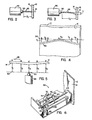
- FIG. 1 the method and apparatus of the present invention are shown by way of example as embodied in a large scale sign generating system shown in perspective view in Fig. 1 and designated generally by the numeral 10.
- panels 12, 12 collectively providing a receiving surface 14 are mounted on an endless conveyor designated generally at 16, for movement past a dot applying printing station 18.
- the conveyor 16 includes wheels 20, 20 which follow a guide track 22.
- a drive means 24 has a pinion gear (not shown) which engages a rack 26 on the conveyor 16 to drive it and the attached panels 12, 12 past the printing station 18 in the direction of the arrow 28.
- color dot applicator means in the form of an ink-jet printing mechanism 30 embodying the present invention is disposed in front of the panels 12, 12 and is driven vertically along an upright supporting column 32 by a driving means 34, as indicated by arrow 36, perpendicular to the direction of movement of the panels.
- a supply of pigmented inks or other colored liquids is provided to the printing mechanism 30 from a number of reservoirs 38, 38 by associated conduits 40, 40.
- a computer 42 controls the drive means 34, the drive means 24 and the printing mechanism 30 via a cable 44 and causes the printing mechanism 30 to apply colored dots to the receiving surface 14 to produce a desired color sign or other display.
- FIG. 2 an elevational schematic side view of an ink-jet head.and section of a receiving surface panel are shown therein.
- an ink-jet head 46 and its associated nozzle 50 are shown at a spacing Zl from the receiving surface 14 of a panel 12.
- the distance Zl is such that ink drops 48, 48 ejected from the ink-jet nozzle 50 follow a straight line trajectory along a reference line 51 passing through the nozzle perpendicular to the receiving surface 14.
- FIG. 3 an ink-jet head 46 and its associated nozzle 50 are shown at a spacing Z2 from the receiving surface 14 of a panel 12.
- the spacing Z2 is greater than a maximum spacing beyond which a straight line trajectory cannot be maintained.
- the printing location on the receiving surface 14 becomes lower increasing the distance Y.
- a straight line is printed as the printing head 46 moves in a scanning relationship with the surface 14 and either head to surface spacing or other spacings can be used to generate the desired graphic display.
- changes in the spacing between the ink-jet head 46 and the receiving surface 14 from a preset spacing as the head scans across the surface causes ejected ink drops to be applied at undesired printing locations on the surface and produces a distorted or wavy line as explained in more detail below.
- Fig. 4 is a perspective view showing a panel of the type used to form the receiving surface in the sign generating system of Fig. 1.
- the panel of Fig. 4 is shown with a structural distortion or warpage.
- Fig. 5 shows a schematic top plan view of the panel of Fig. 4 and an ink-jet printing head 46 illustrating spacing variations at locations along one scanned line on the receiving surface 14 with respect to a reference line 52 passing through the ink-jet nozzle 50 parallel to the direction of movement of the panel 12 as shown by the direction arrow 28.
- a scanned line 54 is printed on the receiving surface 14 and has selected printing locations designated at A, B, C, D and E and correspond to like lettered printing locations shown in Fig. 5.
- the ink-jet printing head 46 is set at a spacing X3 at printing location C as shown in Fig. 5
- a corresponding dot is printed at the printing location C on the receiving surface 14 at the desired location along the scan line 54 as shown in Fig. 4.
- Line 54 is shown as it appears on the receiving surface 14 when printed by an ink-jet head having a constant spacing for example, X3, from the surface.
- Line 56 is shown in Fig. 4 as it appears on the receiving surface l4 of the warped panel 12 when ink drops are ejected onto the surface from an ink-jet printing head 46 having a fixed mounting position. As the head 46 moves in a scanning relationship with the surface 14, the spacing between the printing head and the receiving surface varies as the panel moves toward and away from the printing head due to the panel distortion. Line 56 as shown is printed by ink drops ejected from the printing head 46 and has at selected printing locations A, B, C, D and E head to surface spacings of Xl, X2, X3, X4 and X5, respectively from the reference line 52.
- the trajectory is such that an ink drop lands on the receiving surface at distances Yl, Y2, Y4 and Y5 below the scanned line 54 for printing locations A, B, D and E respectively.
- a wavy or irregular line is printed on the surface of a warped panel due to spacing variations between the printing head 46 and the receiving surface 14 as the printing head moves in a scanning relationship with the surface.
- an ink-jet head positioning apparatus embodying the present invention is shown in perspective view and is designated generally by the numeral 58.
- An ink-jet-head 46 is attached to a moveable mounting member 60 which is driven along a guide means 64 in the direction of arrow 68 by a drive means 62 coupled to the mounting member by a bracket 66.
- An ultrasonic transducer means 70 is coupled to and moves with the ink-jet printing head 46 and mounting member 60.
- the transducer 70 and printing head 46 are arranged in a side-by-side relationship so that a printing location on the receiving surface 14 passes the transducer for sensing and adjustment of, if necessary, the head to surface spacing prior to printing at the location.
- An electrical circuit designated generally at 72 controls the operation of the transducer 70 through a cable 74.
- a trans mitting portion of the circuit 72 causes transducer 70 to transmit ultrasonic signals to the receiving surface 14 at timed intervals.
- the transducer 70 is also connected to a receiving portion of the circuit 72 which is enabled to amplify sensed reflected signals or echos from the surface 14 received within a predetermined time interval or receiving time window between successive transmissions.
- the spacing between the printing head 46 and the receiving surface 14 is related to the time interval between transmission to and receiving the signal reflected from the surface.
- a positioning signal for driving a servomotor 80 is produced by comparing a reference position signal representative of the time interval between transmission and return at the desired head to surface spacing to a printing location position signal representative of the time interval between transmission and return at the printing location head to surface spacing.
- the ink-jet printing head 46 is spaced relative to the receiving surface 14 for each printing location in accordance with the positioning signal coupled from the circuit 72 to the servomotor 80 via a cable 76.
- a limit switch 78 is mechanically actuated by the mounting member 60 to disconnect driving voltage of one polarity from the servomotor 80 when the time interval between transmission and sensing of the reflected signal is such to produce a positioning signal that, if not interrupted, retracts the transducer 70 away from the surface 14 and out of its operating range.
- a positioning signal is generated, for example, when the spacing between the printing head 46 and the surface 14 is greater than a predetermined distance such as at a gap between two abutting panels.
- the switch 78 is returned to its normally closed position when the time interval between transmission and sensing of the reflected signal is within the proper range to produce a positioning signal of the opposite polarity to operate the servomotor 80 to move the head 46 and transducer 70 toward the surface.
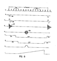
- Figs. 7 and 8 a functional block diagram partially in schematic form of the ink-jet head positioning circuit is shown in Fig. 7 and is designated generally by the number 72.
- Figs. 8a-8i show representative voltage waveforms at various points in the circuit of Fig. 7.
- An oscillator designated generally at 81 generates pulses 82, 82 shown in Fig. 8a at a frequency of 16 kilohertz.
- the pulses 82, 82 are two microseconds in duration and are fed via lead 84 to a counter 86.
- the counter 86 is a 16 count binary up counter and generates a carrier out pulse 83 shown in Fig.
- the carrier out pulse 83 is fed to a bipolar pulse generator and driver circuit designated at 90 which circuit generates a bipolar pulse 85 shown in Fig. 8c having a positive and negative pulse width of 2.3 microseconds.
- the bipolar pulse 85 drives transducer 70 via lead 74 once every millisecond to cause the transducer to transmit an ultrasonic signal 87 shown in Fig. 8d at its resonant frequency to the receiving surface.
- the output of counter 86 is fed to a decoder and timing control circuit designated at 92 via leads 94.
- the decoder 92 is a 4 to 1 of 16 decoder coupled to set/reset timing logic to generate timing pulses and enabling signals in the circuit 72 as explained below.
- a reflected signal or echo 89 shown in Fig. 8e is sensed by the transducer 70 and is coupled via lead 74 to a receiving portion of the circuitry 72 designated generally within the dotted line enclosure 96.
- the receiving circuit 96 is enabled for a predetermined interval between successive transmissions to receive and amplify a sensed reflected signal. Reflected signals appearing at the transducer 70 outside the receiving window are not sensed and the ink-jet head is retracted as mentioned above until a reflected signal is sensed within the receiving window.
- a reflected signal arrives at the transducer 70 prior to the window opening when the printing head to surface spacing is smaller than a predetermined spacing.
- a reflected signal arrives at the transducer 70 after the window is closed when the printing head to surface spacing is greater than a predetermined spacing. Reflected signals arrive at the transducer within the window when the printing head to surface spacing is within a desired spacing range and corresponds in the present invention to a transducer to surface spacing in the range of three to five inches.
- the input of a high gain amplifier 98 is connected to the transducer 70 via lead 74 and to ground through an FET 100.
- the gate of FET 100 is connected to the decoder and timing control circuit 92 via lead 101.
- the FET 100 holds the input to amplifier 98 at ground potential until it is turned OFF by the decoder and timing control circuit 92 on the third count after a signal has been transmitted by the ultrasonic transducer 70.
- the FET 100 is turned ON again on the sixteenth count.
- the ON and OFF voltage signals for FET 100 are shown in Fig. 8f.
- the reflected signal if present between the third and sixteenth count, is amplified by amplifier 98 and is coupled to an input of a second high gain amplifier 102.
- the input to amplifier 102 is also shunted to ground by an FET 104 which is controlled by and connected via lead 103 to the decoder and timing control circuit 92.
- the FET 104 holds the input to amplifier 102 at ground potential until it is turned OFF on the fourth count after a signal is transmitted by transducer 70.
- the FET 104 is turned ON again on the fifteenth count.
- the ON and OFF voltage signals for FET 104 are shown in Fig. 8g.
- Amplifier 102 further amplifies the reflected signal between the fourth and fifteen the count and its output is connected to an analog switch 106.
- the analog switch 106 is connected to the decoder and timing control circuit 92 via lead 103 and couples the signal from amplifier 102 to the input of a halfwave rectifier via lead 108 during the same time interval that FET 104 is OFF.
- the halfwave rectifier is made up of amplifier 110 and diode 112.
- the halfwave rectified signal is filtered by a filter 114 to remove the transducer resonant frequency from the halfwave rectified signal.
- the output of the filter 114 shown in Fig. 8h is fed to the input of an edge triggered detector 116 which produces an output pulse when the voltage at its inverting terminal exceeds a triggering voltage reference level established by the combination of zener diode 118 and resistor 120.
- the output of detector 116 is fed via lead 124 to a sample and hold timing control logic circuit designated generally at 122.
- the sample and hold logic circuit 122 contains set/reset circuitry to generate a signal on lead 128 which is coupled through capacitor 129 to an electronic switch 130.
- a reset voltage signal coincidental with the time FET 104 is OFF, is generated by the decoder and timing circuit on lead 126 to reset the sample and hold logic circuit 122 to generate an output pulse on lead 128 each time a reflected signal is received and detected within the receiving window.
- the electronic switch 130 is a normally open switch and operates momentarily each time a pulse is generated on lead 128. The momentary operation is caused by the capacitive coupling from the logic circuit 122 output to the switch input.
- a ramp generator comprised of amplifier 132 and capacitor-134 is a time to voltage converter and generates a ramp voltage at the output of amplifier 132 which is connected to one side of the electronic switch 130 by lead 136.
- the charging and discharging of capacitor 134 is controlled by a normally closed electronic switch 138 connected in parallel with the capacitor.
- the switch 138 is operated to its open condition allowing capacitor 134 to charge during the time that the reset voltage is present on lead 126 to produce the ramp voltage as shown by the waveform in Fig. 8i.
- Capacitor 134 discharges when switch 138 is returned to its closed condition.
- the magnitude of the ramp voltage at any point along the ramp is proportional to the time a reflected signal is sensed by the transducer 70 after a transmission.
- the input of a sample and hold circuit comprised of amplifier 140 and a holding capacitor 142 is connected to the other side of electronic switch 130 by lead 144.
- the holding capacitor 142 is charged to the ramp generator output voltage each time switch 130 is operated to its closed condition.
- the sample and hold amplifier 140 is configured as a voltage follower and its output on lead 145 is a voltage signal following the magnitude of the voltage across the holding capacitor. Consequently, the output voltage signal has a magnitude representative of the position of the transducer 70 and accordingly the spacing between the transducer 70 and the receiving surface 14.
- the position signal is fed to the input of a positioning amplifier 146 which compares the voltage of the position signal to a reference voltage representative of a desired spacing between the printing head 46 and the receiving surface 14.
- the output of amplifier 146 is a position error voltage signal on lead 150 and is coupled to a servomotor drive circuit 152.
- the drive circuit 152 provides a negative or positive polarity driving voltage on lead 154 through the limit switch 78 to power servomotor 80.
- switch 78 When switch 78 operates as described above, the negative polarity driving voltage causing the servomotor 80 to retract the printing head 46 and transducer 70 is removed.
- the servomotor 80 will now only operate with a positive driving voltage being applied through a diode 160 which blocks negative driving voltages.
- a positive voltage causes servomotor 80 to move the head and transducer toward the receiving surface causing switch 78 to release to its closed position.
- the reference position voltage level is set by adjusting potentiometer 147 to provide a voltage on lead 148 which when fed to the input of amplifier 146 causes a zero position error voltage to be produced at the output of amplifier 146 when the spacing between the printing head 46 and the receiving surface 14 is at the desired spacing.
- the servomotor 80 is connected to a tachometer 156 via lead 157 to provide a velocity feedback voltage signal on lead 158 to the servomotor drive circuit 152.
- the position error signal on lead 150 and the velocity feedback signal on 158 are summed in accordance with well know closed loop servo system concepts to drive the servomotor and accordingly maintain the desired spacing between the ink-jet head 46 and receiving surface 14.
Abstract
Description
- The present invention relates generally to ink-jet printing and deals more particularly with an ink-jet positioning apparatus or circuit and a related method for maintaining a desired spacing between an ink-jet printing means and a receiving surface.
- Ink-jet printing devices such as, for example, non-impact matrix printers and the like, print alphanumeric characters, graphics or other such displays by generally ejecting ink drops or dots onto a receiving surface in accordance with control information provided to operate an ink-jet printing head. Generally, the receiving surface is held stationary against a back support or other means relative to the printing head to maintain a constant spacing between the head and the surface. As the printer head moves along a scan line it moves past a succession of points on the line in relation to each of which the printer head may eject an ink drop which lands on and prints a dot at that position. The flight of an ink drop in such ink-jet printing devices where a constant spacing is maintained between the ink-jet head and a receiving surface is at a fixed, uniform trajectory for each dot printed. Such ink-jet printing devices are commonly know in the art.
- The recording medium forming the receiving surface used in such printing devices is generally of a uniform thickness and structurally undistorted so that there is no variation in the spacing between the ink-jet printing head and the surface along a line scanned by the head. Consequently, the ink-jet printing head in these devices can be positioned closely to the receiving surface and once positioned are able to maintain the desired spacing without additional adjustment during the printing process.
- In some graphics display generating devices such as, for example, large scale sign generators for printing roadside billboards and the like, ink-jet printing techniques are used to produce a desired sign or other display. In one such large scale sign generator, panels used as the recording medium are placed in a side-to-side abutting relationship and pass in endless conveyor fashion by a dot printing mechanism which applies dots onto the face or receiving surface of the panels in a scanning fashion to produce the desired display. Often times the panels used as the recording medium are warped or have other structural distortions affecting the uniformity of the receiving surface. Such warped panels cause the spacing between the ink-jet printing head and the receiving surface to vary from a preset or desired spacing as the panels move by the dot applying station.
- If the spacing increases placing the receiving surface too far from the printing head, the ejected ink drops start to drop before landing on the surface. Consequently, dots applied to a succession of points along a line on a warped receiving surface print a wavy or irregular line rather than a straight line. If the spacing becomes to small, the receiving surface is brought into contact with the printing mechanism causing damage to the ink-jet printing head. It would therefore be desireable to have a continuously variable positioning ink-jet printing head to compensate for movement of the receiving surface toward and away from the printing head to maintain a constant spacing between the receiving surface and the printing head at the printing location for each printing location.
- It is therefore a general aim of the present invention to provide positioning apparatus for maintaining a desired spacing between an associated ink-jet printing head and a receiving surface at a printing location.
- Other features and advantages of the present invention will become readily apparent from the following written description and the drawings forming a part thereof.
- The present invention resides in positioning apparatus and a related method for maintaining a desired spacing between an ink-jet printing means and a receiving surface along a line scanned by the printing means. Means are provided for transmitting a signal at timed intervals to the receiving surface from the printing means. Other means are provided for sensing during a predetermined receiving time window a signal reflected from the receiving surface after transmitting the signal.
- Means are also provided to produce a reference position signal representative of the desired spacing and other means are provided to produce a printing location position signal representative of the spacing at a printing location in response to the reflected signal sensing means. The printing location spacing is compared to the desired spacing by comparing means.
- Means are provided for moving the printing means toward and away from the receiving surface in response to the comparing means to maintain the printing means to surface spacing at the desired spacing.
-
- Fig. 1 shows a perspective view of a large scale sign generating system having apparatus embodying the present invention for positioning an ink-jet printing head relative to a receiving surface to maintain a desired spacing between the ink-jet head and the receiving surface.
- Fig. 2 is a schematic view showing the trajectory of ejected ink drops onto a receiving surface at a desired spacing between an ink-jet head and the receiving surface.
- Fig. 3 is a schematic view showing the trajectory of ejected ink drops onto a receiving surface at a spacing between an ink-jet head and the receiving surface which causes the ink drops to drop before landing on the surface.
- Fig. 4 is a perspective view showing a panel of the type used as the receiving surface in the sign generating system of Fig. 1 in which the panel shown is warped.
- Fig. 5 is a schematic top plan view of the panel of Fig. 4 and an ink-jet printing head illustrating spacing variations at locations along one scan line on the receiving surface with reference to a line passing through the ink-jet head.
- Fig. 6 is a perspective view showing an ink-jet printing head positioning apparatus embodying the present invention.
- Fig. 7 is a functional block diagram partially in schematic form of an ink-jet head positioning circuit embodying the present invention.
- Figs. 8a-8i show timing and voltage waveforms at various locations in the circuit of Fig. 7.
- Referring now to the drawings, the method and apparatus of the present invention are shown by way of example as embodied in a large scale sign generating system shown in perspective view in Fig. 1 and designated generally by the
numeral 10. Briefly,panels surface 14 are mounted on an endless conveyor designated generally at 16, for movement past a dot applying printing station 18. Theconveyor 16 includeswheels guide track 22. A drive means 24 has a pinion gear (not shown) which engages arack 26 on theconveyor 16 to drive it and the attachedpanels arrow 28. - At the printing station 18, color dot applicator means in the form of an ink-
jet printing mechanism 30 embodying the present invention is disposed in front of thepanels driving means 34, as indicated by arrow 36, perpendicular to the direction of movement of the panels. A supply of pigmented inks or other colored liquids is provided to theprinting mechanism 30 from a number of reservoirs 38, 38 by associated conduits 40, 40. - A
computer 42 controls the drive means 34, the drive means 24 and theprinting mechanism 30 via acable 44 and causes theprinting mechanism 30 to apply colored dots to thereceiving surface 14 to produce a desired color sign or other display. - Referring now to Figs. 2 and 3, an elevational schematic side view of an ink-jet head.and section of a receiving surface panel are shown therein. In Fig. 2 an ink-
jet head 46 and its associatednozzle 50 are shown at a spacing Zl from thereceiving surface 14 of apanel 12. The distance Zl is such that ink drops 48, 48 ejected from the ink-jet nozzle 50 follow a straight line trajectory along areference line 51 passing through the nozzle perpendicular to thereceiving surface 14. Referring to Fig. 3, an ink-jet head 46 and its associatednozzle 50 are shown at a spacing Z2 from thereceiving surface 14 of apanel 12. The spacing Z2 is greater than a maximum spacing beyond which a straight line trajectory cannot be maintained. The ejectedink drops surface 14 follow a dropping trajectory such that dots are applied to printing locations at a distance Y below thereference line 51 passing through thenozzle 50. As the spacing between thehead 46 and thesurface 14 increases, the printing location on thereceiving surface 14 becomes lower increasing the distance Y. - In the head to surface spacing shown in both Figs. 2 and 3, a straight line is printed as the
printing head 46 moves in a scanning relationship with thesurface 14 and either head to surface spacing or other spacings can be used to generate the desired graphic display. However, changes in the spacing between the ink-jet head 46 and thereceiving surface 14 from a preset spacing as the head scans across the surface causes ejected ink drops to be applied at undesired printing locations on the surface and produces a distorted or wavy line as explained in more detail below. - Referring now to Figs. 4 and 5, Fig. 4 is a perspective view showing a panel of the type used to form the receiving surface in the sign generating system of Fig. 1. The panel of Fig. 4 is shown with a structural distortion or warpage. Fig. 5 shows a schematic top plan view of the panel of Fig. 4 and an ink-
jet printing head 46 illustrating spacing variations at locations along one scanned line on thereceiving surface 14 with respect to areference line 52 passing through the ink-jet nozzle 50 parallel to the direction of movement of thepanel 12 as shown by thedirection arrow 28. For purposes of explanation and by way of example, a scannedline 54 is printed on thereceiving surface 14 and has selected printing locations designated at A, B, C, D and E and correspond to like lettered printing locations shown in Fig. 5. For example, when the ink-jet printing head 46 is set at a spacing X3 at printing location C as shown in Fig. 5, a corresponding dot is printed at the printing location C on thereceiving surface 14 at the desired location along thescan line 54 as shown in Fig. 4.Line 54 is shown as it appears on thereceiving surface 14 when printed by an ink-jet head having a constant spacing for example, X3, from the surface. -
Line 56 is shown in Fig. 4 as it appears on the receiving surface l4 of the warpedpanel 12 when ink drops are ejected onto the surface from an ink-jet printing head 46 having a fixed mounting position. As thehead 46 moves in a scanning relationship with thesurface 14, the spacing between the printing head and the receiving surface varies as the panel moves toward and away from the printing head due to the panel distortion.Line 56 as shown is printed by ink drops ejected from theprinting head 46 and has at selected printing locations A, B, C, D and E head to surface spacings of Xl, X2, X3, X4 and X5, respectively from thereference line 52. Because the ink drops have a greater distance to travel at printing locations A, B, D and E compared to the distance at location C, the trajectory is such that an ink drop lands on the receiving surface at distances Yl, Y2, Y4 and Y5 below the scannedline 54 for printing locations A, B, D and E respectively. Thus it can be seen that a wavy or irregular line is printed on the surface of a warped panel due to spacing variations between theprinting head 46 and thereceiving surface 14 as the printing head moves in a scanning relationship with the surface. - Referring now to Fig. 6, an ink-jet head positioning apparatus embodying the present invention is shown in perspective view and is designated generally by the
numeral 58. An ink-jet-head 46 is attached to amoveable mounting member 60 which is driven along a guide means 64 in the direction of arrow 68 by a drive means 62 coupled to the mounting member by abracket 66. An ultrasonic transducer means 70 is coupled to and moves with the ink-jet printing head 46 and mountingmember 60. Thetransducer 70 andprinting head 46 are arranged in a side-by-side relationship so that a printing location on thereceiving surface 14 passes the transducer for sensing and adjustment of, if necessary, the head to surface spacing prior to printing at the location. - An electrical circuit designated generally at 72 controls the operation of the
transducer 70 through acable 74. As explained in greater detail below, a trans mitting portion of thecircuit 72causes transducer 70 to transmit ultrasonic signals to the receivingsurface 14 at timed intervals. Thetransducer 70 is also connected to a receiving portion of thecircuit 72 which is enabled to amplify sensed reflected signals or echos from thesurface 14 received within a predetermined time interval or receiving time window between successive transmissions. The spacing between theprinting head 46 and the receivingsurface 14 is related to the time interval between transmission to and receiving the signal reflected from the surface. - A positioning signal for driving a
servomotor 80 is produced by comparing a reference position signal representative of the time interval between transmission and return at the desired head to surface spacing to a printing location position signal representative of the time interval between transmission and return at the printing location head to surface spacing. The ink-jet printing head 46 is spaced relative to the receivingsurface 14 for each printing location in accordance with the positioning signal coupled from thecircuit 72 to theservomotor 80 via acable 76. - A
limit switch 78 is mechanically actuated by the mountingmember 60 to disconnect driving voltage of one polarity from theservomotor 80 when the time interval between transmission and sensing of the reflected signal is such to produce a positioning signal that, if not interrupted, retracts thetransducer 70 away from thesurface 14 and out of its operating range. Such a positioning signal is generated, for example, when the spacing between theprinting head 46 and thesurface 14 is greater than a predetermined distance such as at a gap between two abutting panels. Theswitch 78 is returned to its normally closed position when the time interval between transmission and sensing of the reflected signal is within the proper range to produce a positioning signal of the opposite polarity to operate theservomotor 80 to move thehead 46 andtransducer 70 toward the surface. - Considering now the electrical circuit of the present invention in more detail and referring to Figs. 7 and 8, a functional block diagram partially in schematic form of the ink-jet head positioning circuit is shown in Fig. 7 and is designated generally by the
number 72. Figs. 8a-8i show representative voltage waveforms at various points in the circuit of Fig. 7. An oscillator designated generally at 81 generatespulses pulses lead 84 to acounter 86. Thecounter 86 is a 16 count binary up counter and generates a carrier outpulse 83 shown in Fig. 8b onlead 88 each time the count reaches 16 or once every millisecond. The carrier outpulse 83 is fed to a bipolar pulse generator and driver circuit designated at 90 which circuit generates abipolar pulse 85 shown in Fig. 8c having a positive and negative pulse width of 2.3 microseconds. Thebipolar pulse 85drives transducer 70 vialead 74 once every millisecond to cause the transducer to transmit anultrasonic signal 87 shown in Fig. 8d at its resonant frequency to the receiving surface. - The output of
counter 86 is fed to a decoder and timing control circuit designated at 92 via leads 94. Thedecoder 92 is a 4 to 1 of 16 decoder coupled to set/reset timing logic to generate timing pulses and enabling signals in thecircuit 72 as explained below. - A reflected signal or echo 89 shown in Fig. 8e is sensed by the
transducer 70 and is coupled vialead 74 to a receiving portion of thecircuitry 72 designated generally within the dottedline enclosure 96. The receivingcircuit 96 is enabled for a predetermined interval between successive transmissions to receive and amplify a sensed reflected signal. Reflected signals appearing at thetransducer 70 outside the receiving window are not sensed and the ink-jet head is retracted as mentioned above until a reflected signal is sensed within the receiving window. A reflected signal arrives at thetransducer 70 prior to the window opening when the printing head to surface spacing is smaller than a predetermined spacing. A reflected signal arrives at thetransducer 70 after the window is closed when the printing head to surface spacing is greater than a predetermined spacing. Reflected signals arrive at the transducer within the window when the printing head to surface spacing is within a desired spacing range and corresponds in the present invention to a transducer to surface spacing in the range of three to five inches. - The input of a
high gain amplifier 98 is connected to thetransducer 70 vialead 74 and to ground through anFET 100. The gate ofFET 100 is connected to the decoder andtiming control circuit 92 via lead 101. TheFET 100 holds the input toamplifier 98 at ground potential until it is turned OFF by the decoder andtiming control circuit 92 on the third count after a signal has been transmitted by theultrasonic transducer 70. TheFET 100 is turned ON again on the sixteenth count. The ON and OFF voltage signals forFET 100 are shown in Fig. 8f. The reflected signal, if present between the third and sixteenth count, is amplified byamplifier 98 and is coupled to an input of a secondhigh gain amplifier 102. - The input to
amplifier 102 is also shunted to ground by anFET 104 which is controlled by and connected vialead 103 to the decoder andtiming control circuit 92. TheFET 104 holds the input toamplifier 102 at ground potential until it is turned OFF on the fourth count after a signal is transmitted bytransducer 70. TheFET 104 is turned ON again on the fifteenth count. The ON and OFF voltage signals forFET 104 are shown in Fig. 8g.Amplifier 102 further amplifies the reflected signal between the fourth and fifteen the count and its output is connected to ananalog switch 106. - The
analog switch 106 is connected to the decoder andtiming control circuit 92 vialead 103 and couples the signal fromamplifier 102 to the input of a halfwave rectifier vialead 108 during the same time interval thatFET 104 is OFF. The halfwave rectifier is made up ofamplifier 110 anddiode 112. The halfwave rectified signal is filtered by a filter 114 to remove the transducer resonant frequency from the halfwave rectified signal. The output of the filter 114 shown in Fig. 8h is fed to the input of an edge triggereddetector 116 which produces an output pulse when the voltage at its inverting terminal exceeds a triggering voltage reference level established by the combination ofzener diode 118 andresistor 120. - The output of
detector 116 is fed vialead 124 to a sample and hold timing control logic circuit designated generally at 122. The sample and holdlogic circuit 122 contains set/reset circuitry to generate a signal onlead 128 which is coupled throughcapacitor 129 to anelectronic switch 130. A reset voltage signal coincidental with thetime FET 104 is OFF, is generated by the decoder and timing circuit onlead 126 to reset the sample and holdlogic circuit 122 to generate an output pulse onlead 128 each time a reflected signal is received and detected within the receiving window. - The
electronic switch 130 is a normally open switch and operates momentarily each time a pulse is generated onlead 128. The momentary operation is caused by the capacitive coupling from thelogic circuit 122 output to the switch input. - A ramp generator comprised of
amplifier 132 and capacitor-134 is a time to voltage converter and generates a ramp voltage at the output ofamplifier 132 which is connected to one side of theelectronic switch 130 bylead 136. The charging and discharging ofcapacitor 134 is controlled by a normally closedelectronic switch 138 connected in parallel with the capacitor. Theswitch 138 is operated to its opencondition allowing capacitor 134 to charge during the time that the reset voltage is present onlead 126 to produce the ramp voltage as shown by the waveform in Fig. 8i.Capacitor 134 discharges whenswitch 138 is returned to its closed condition. The magnitude of the ramp voltage at any point along the ramp is proportional to the time a reflected signal is sensed by thetransducer 70 after a transmission. - The input of a sample and hold circuit comprised of
amplifier 140 and a holdingcapacitor 142 is connected to the other side ofelectronic switch 130 bylead 144. The holdingcapacitor 142 is charged to the ramp generator output voltage eachtime switch 130 is operated to its closed condition. The sample and holdamplifier 140 is configured as a voltage follower and its output onlead 145 is a voltage signal following the magnitude of the voltage across the holding capacitor. Consequently, the output voltage signal has a magnitude representative of the position of thetransducer 70 and accordingly the spacing between thetransducer 70 and the receivingsurface 14. - If reflected signals are not sensed within the receiving window,
electronic switch 130 does not complete the charging path for holdingcapacitor 142 and the voltage across the capacitor decays to zero thereby causing the output ofamplifier 140 to fall to zero. - The position signal is fed to the input of a
positioning amplifier 146 which compares the voltage of the position signal to a reference voltage representative of a desired spacing between theprinting head 46 and the receivingsurface 14. The output ofamplifier 146 is a position error voltage signal onlead 150 and is coupled to aservomotor drive circuit 152. Thedrive circuit 152 provides a negative or positive polarity driving voltage onlead 154 through thelimit switch 78 topower servomotor 80. - When
switch 78 operates as described above, the negative polarity driving voltage causing theservomotor 80 to retract theprinting head 46 andtransducer 70 is removed. Theservomotor 80 will now only operate with a positive driving voltage being applied through adiode 160 which blocks negative driving voltages. A positive voltage causes servomotor 80 to move the head and transducer toward the receivingsurface causing switch 78 to release to its closed position. - The reference position voltage level is set by adjusting
potentiometer 147 to provide a voltage onlead 148 which when fed to the input ofamplifier 146 causes a zero position error voltage to be produced at the output ofamplifier 146 when the spacing between theprinting head 46 and the receivingsurface 14 is at the desired spacing. - The
servomotor 80 is connected to atachometer 156 vialead 157 to provide a velocity feedback voltage signal onlead 158 to theservomotor drive circuit 152. The position error signal onlead 150 and the velocity feedback signal on 158 are summed in accordance with well know closed loop servo system concepts to drive the servomotor and accordingly maintain the desired spacing between the ink-jet head 46 and receivingsurface 14. - An ink-jet head positioning apparatus has been described in one preferred embodiment; however, numerous modifications and changes may be had without departing from the spirit of the invention. Therefore, the invention has been described by way of illustration rather than of limitation.
Claims (15)
Priority Applications (1)
| Application Number | Priority Date | Filing Date | Title |
|---|---|---|---|
| AT85108747T ATE51584T1 (en) | 1984-08-02 | 1985-07-12 | DEVICE AND METHOD FOR ADJUSTING AN INKJET PRINT HEAD. |
Applications Claiming Priority (2)
| Application Number | Priority Date | Filing Date | Title |
|---|---|---|---|
| US637161 | 1984-08-02 | ||
| US06/637,161 US4580914A (en) | 1984-08-02 | 1984-08-02 | Apparatus and method for positioning an ink-jet printing head |
Publications (3)
| Publication Number | Publication Date |
|---|---|
| EP0170137A2 true EP0170137A2 (en) | 1986-02-05 |
| EP0170137A3 EP0170137A3 (en) | 1987-01-14 |
| EP0170137B1 EP0170137B1 (en) | 1990-04-04 |
Family
ID=24554804
Family Applications (1)
| Application Number | Title | Priority Date | Filing Date |
|---|---|---|---|
| EP85108747A Expired - Lifetime EP0170137B1 (en) | 1984-08-02 | 1985-07-12 | Apparatus and method for positioning an ink-jet printing head |
Country Status (7)
| Country | Link |
|---|---|
| US (1) | US4580914A (en) |
| EP (1) | EP0170137B1 (en) |
| JP (1) | JPH0643127B2 (en) |
| AT (1) | ATE51584T1 (en) |
| CA (1) | CA1251093A (en) |
| DE (1) | DE3576938D1 (en) |
| GB (1) | GB2162617B (en) |
Cited By (8)
| Publication number | Priority date | Publication date | Assignee | Title |
|---|---|---|---|---|
| EP0317219A2 (en) * | 1987-11-13 | 1989-05-24 | L. A. C. Corporation | Automatic printing device |
| FR2642702A1 (en) * | 1989-01-18 | 1990-08-10 | Morival Serge | Flexible marking machine |
| DE4101743A1 (en) * | 1991-01-22 | 1992-07-23 | Anliker Hedwig | Mechanical brickwork finishing system - has bricks or stones in arrangement individually in row in series longitudinal direction conveyed with pref. constant speed to displacement system and passing stone side is given identity mark |
| EP0566540A2 (en) * | 1992-02-26 | 1993-10-20 | Canon Kabushiki Kaisha | Recording apparatus and method for the manufacturing of a product with this apparatus |
| EP0602251A1 (en) * | 1992-06-24 | 1994-06-22 | Sony Corporation | Printing method, printer, printing head, container for accommodating printed matters and printing method of cassette |
| EP0657294A2 (en) * | 1993-12-09 | 1995-06-14 | Seiko Epson Corporation | Automatic platen gap adjusting device for printer |
| EP0761438A2 (en) * | 1995-09-05 | 1997-03-12 | Tampoprint GmbH | Device for applying designs |
| EP1065055A1 (en) * | 1999-07-01 | 2001-01-03 | SARL A I M Société à responsabilité limitée | Device for decorating voluminous objects |
Families Citing this family (19)
| Publication number | Priority date | Publication date | Assignee | Title |
|---|---|---|---|---|
| ES8703298A1 (en) * | 1986-05-23 | 1987-03-01 | Sanchez Robles Beltran Francis | Color dosification/applicaion machine |
| FR2601265B1 (en) * | 1986-05-28 | 1988-08-05 | Cherubin Grillo Victor | PICTURAL POINT-BY-POINT POLYCHROME PRINTING SYSTEM ON A FLAT OR RELIEF SURFACE, CONTROLLED BY MICRO-PROCESSOR. |
| JPH01110159A (en) * | 1987-10-23 | 1989-04-26 | L Ee C:Kk | Automatic image drawing apparatus |
| FR2628658B1 (en) * | 1988-03-18 | 1990-08-10 | Lapierre Gilles | AUTOMATIC METHODS AND DEVICES FOR WRITING HIGH RESOLUTION GRAPHICS ONTO A SUBJECTILE BY SPRAYING COLORED LIQUID DROPS |
| JPH0286457A (en) * | 1988-09-22 | 1990-03-27 | Canon Inc | Liquid jet recording device |
| DE4039742A1 (en) * | 1990-12-08 | 1992-06-11 | Francotyp Postalia Gmbh | LIQUID JET PRINTING DEVICE FOR STAMPING AND VALUE STAMPING MACHINES |
| US5757389A (en) * | 1991-09-25 | 1998-05-26 | Horst Schwede | Printing device for objects, which are continously moved forward, in particular for parcels, wrapped magazine piles or the like |
| US5529405A (en) * | 1993-02-01 | 1996-06-25 | International Business Machines Corporation | Manual control/override for automatic forms thickness adjustment |
| US5427029A (en) * | 1994-01-25 | 1995-06-27 | Professional Control Corporation | Method and apparatus for providing printed labels for large numbers of objects |
| GB2287772A (en) * | 1994-03-10 | 1995-09-27 | Raymond George Coughlin | Gate valve stem sealing arrangement |
| EP0787586A4 (en) * | 1994-10-20 | 1998-04-01 | Omron Tateisi Electronics Co | Printing device and postage franking machine |
| US5646654A (en) * | 1995-03-09 | 1997-07-08 | Hewlett-Packard Company | Ink-jet printing system having acoustic transducer for determining optimum operating energy |
| KR100186611B1 (en) * | 1996-06-26 | 1999-05-15 | 김광호 | Paper thickness sensing device of image recording apparatus and recording head auto-controlling apparatus of inkjet recording apparatus and method thereof |
| US6578276B2 (en) | 1998-01-27 | 2003-06-17 | Eastman Kodak Company | Apparatus and method for marking multiple colors on a contoured surface having a complex topography |
| EP0931649A3 (en) | 1998-01-27 | 2000-04-26 | Eastman Kodak Company | Apparatus and method for making a contoured surface having complex topology |
| DE19808262A1 (en) * | 1998-02-27 | 1999-09-09 | Lensing | Printing of surface of curved object |
| US7008128B1 (en) * | 2000-07-27 | 2006-03-07 | Tadayoshi Nakanishi | System, method and apparatus for printing oversized print media |
| US6561607B1 (en) * | 2000-10-05 | 2003-05-13 | Eastman Kodak Company | Apparatus and method for maintaining a substantially constant closely spaced working distance between an inkjet printhead and a printing receiver |
| US20080145126A1 (en) * | 2006-10-19 | 2008-06-19 | Th, Inc. | Controlled Application of Pigments to Select Regions on a Surface of a Substrate |
Citations (3)
| Publication number | Priority date | Publication date | Assignee | Title |
|---|---|---|---|---|
| FR2342163A1 (en) * | 1976-02-28 | 1977-09-23 | Ncr Co | PRINTERS |
| GB2006117A (en) * | 1977-10-25 | 1979-05-02 | Solution Sciences Inc | Direct laser printing and forming apparatus |
| WO1979000955A1 (en) * | 1978-04-21 | 1979-11-15 | Baldwin Gegenheimer Corp | Ink level control |
Family Cites Families (12)
| Publication number | Priority date | Publication date | Assignee | Title |
|---|---|---|---|---|
| DE1805145A1 (en) * | 1968-10-25 | 1970-09-03 | Gema Ag Appbau | Set up with spray gun |
| US3867882A (en) * | 1973-04-19 | 1975-02-25 | Houston Eng Res | Apparatus for printing labels directly onto packages, containers and the like |
| JPS5242185B2 (en) * | 1974-10-18 | 1977-10-22 | ||
| JPS51112614A (en) * | 1975-03-29 | 1976-10-05 | Oki Electric Ind Co Ltd | Printer |
| JPS5840507B2 (en) * | 1977-12-29 | 1983-09-06 | 株式会社リコー | Inkjet recording device |
| US4479433A (en) * | 1978-04-21 | 1984-10-30 | Baldwin-Gegenheimer Corporation | Ink level control |
| DE2913229C2 (en) * | 1979-04-03 | 1984-05-17 | Woma-Apparatebau Wolfgang Maasberg & Co Gmbh, 4100 Duisburg | Sliding surface seal |
| US4327923A (en) * | 1979-09-27 | 1982-05-04 | A. W. Chesterton Company | Packing |
| AU1175183A (en) * | 1982-03-08 | 1983-09-15 | Kiwi Coders Corp. | Variable size ink printing |
| US4414792A (en) * | 1982-03-30 | 1983-11-15 | Blackwelders | Height control for agricultural machine |
| US4489916A (en) * | 1982-04-07 | 1984-12-25 | Cameron Iron Works, Inc. | Valve and stem seal therefor |
| JPS5990A (en) * | 1982-06-22 | 1984-01-05 | 松田 修一 | Electric hair clipper |
-
1984
- 1984-08-02 US US06/637,161 patent/US4580914A/en not_active Expired - Fee Related
-
1985
- 1985-02-25 GB GB08504803A patent/GB2162617B/en not_active Expired
- 1985-05-22 JP JP60110087A patent/JPH0643127B2/en not_active Expired - Lifetime
- 1985-07-12 EP EP85108747A patent/EP0170137B1/en not_active Expired - Lifetime
- 1985-07-12 DE DE8585108747T patent/DE3576938D1/en not_active Expired - Lifetime
- 1985-07-12 AT AT85108747T patent/ATE51584T1/en active
- 1985-07-24 CA CA000487419A patent/CA1251093A/en not_active Expired
Patent Citations (3)
| Publication number | Priority date | Publication date | Assignee | Title |
|---|---|---|---|---|
| FR2342163A1 (en) * | 1976-02-28 | 1977-09-23 | Ncr Co | PRINTERS |
| GB2006117A (en) * | 1977-10-25 | 1979-05-02 | Solution Sciences Inc | Direct laser printing and forming apparatus |
| WO1979000955A1 (en) * | 1978-04-21 | 1979-11-15 | Baldwin Gegenheimer Corp | Ink level control |
Non-Patent Citations (1)
| Title |
|---|
| IBM TECHNICAL DISCLOSURE BULLETIN, vol. 26, no. 12, May 1984, pages 6373,6374, New York, US; D.K. REX: "Printhead adjustment" * |
Cited By (15)
| Publication number | Priority date | Publication date | Assignee | Title |
|---|---|---|---|---|
| EP0317219A2 (en) * | 1987-11-13 | 1989-05-24 | L. A. C. Corporation | Automatic printing device |
| EP0317219A3 (en) * | 1987-11-13 | 1990-03-07 | Lac Corp | Automatic printing device automatic printing device |
| FR2642702A1 (en) * | 1989-01-18 | 1990-08-10 | Morival Serge | Flexible marking machine |
| DE4101743A1 (en) * | 1991-01-22 | 1992-07-23 | Anliker Hedwig | Mechanical brickwork finishing system - has bricks or stones in arrangement individually in row in series longitudinal direction conveyed with pref. constant speed to displacement system and passing stone side is given identity mark |
| US5541626A (en) * | 1992-02-26 | 1996-07-30 | Canon Kabushiki Kaisha | Recording apparatus and method for manufacturing recorded product thereby |
| EP0566540A3 (en) * | 1992-02-26 | 1993-12-01 | Canon Kk | Recording apparatus and method for the manufacturing of a product with this apparatus |
| EP0566540A2 (en) * | 1992-02-26 | 1993-10-20 | Canon Kabushiki Kaisha | Recording apparatus and method for the manufacturing of a product with this apparatus |
| EP0602251A1 (en) * | 1992-06-24 | 1994-06-22 | Sony Corporation | Printing method, printer, printing head, container for accommodating printed matters and printing method of cassette |
| EP0602251A4 (en) * | 1992-06-24 | 1995-03-15 | Sony Corp | Printing method, printer, printing head, container for accommodating printed matters and printing method of cassette. |
| EP0657294A2 (en) * | 1993-12-09 | 1995-06-14 | Seiko Epson Corporation | Automatic platen gap adjusting device for printer |
| EP0657294A3 (en) * | 1993-12-09 | 1996-10-30 | Seiko Epson Corp | Automatic platen gap adjusting device for printer. |
| EP0761438A2 (en) * | 1995-09-05 | 1997-03-12 | Tampoprint GmbH | Device for applying designs |
| EP0761438A3 (en) * | 1995-09-05 | 1997-11-05 | Tampoprint GmbH | Device for applying designs |
| EP1065055A1 (en) * | 1999-07-01 | 2001-01-03 | SARL A I M Société à responsabilité limitée | Device for decorating voluminous objects |
| FR2795662A1 (en) * | 1999-07-01 | 2001-01-05 | Sarl A I M | DEVICE PROVIDED WITH A PRINTING HEAD FOR CARRYING OUT DECORATIONS ON LARGE OBJECTS |
Also Published As
| Publication number | Publication date |
|---|---|
| JPH0643127B2 (en) | 1994-06-08 |
| GB8504803D0 (en) | 1985-03-27 |
| GB2162617B (en) | 1988-01-27 |
| ATE51584T1 (en) | 1990-04-15 |
| DE3576938D1 (en) | 1990-05-10 |
| EP0170137A3 (en) | 1987-01-14 |
| CA1251093A (en) | 1989-03-14 |
| JPS6141556A (en) | 1986-02-27 |
| US4580914A (en) | 1986-04-08 |
| GB2162617A (en) | 1986-02-05 |
| EP0170137B1 (en) | 1990-04-04 |
Similar Documents
| Publication | Publication Date | Title |
|---|---|---|
| US4580914A (en) | Apparatus and method for positioning an ink-jet printing head | |
| CA1172684A (en) | Optical sensing of ink jet printing | |
| EP0570167A2 (en) | Method and apparatus for regulating print density in an ink-jet printer | |
| CA1201014A (en) | Variable size ink printing method and apparatus | |
| US3969733A (en) | Sub-harmonic phase control for an ink jet recording system | |
| JPS59214660A (en) | Automatic proof reading of drop-on-demand ink jet ejector | |
| EP0323989B1 (en) | Electronic method and device for adjustment of jet direction in an ink jet apparatus | |
| EP0015727B1 (en) | Electrostatic ink jet printing apparatus and method | |
| GB1475937A (en) | Printing systems | |
| JPH03227249A (en) | Operation of ink jet printing head | |
| ATE348010T1 (en) | INKJET PRINTING APPARATUS AND OUTPUT EVALUATION METHOD OF AN INKJET PRINTHEAD | |
| JPS62116157A (en) | Recorder | |
| US4393385A (en) | Controllable ink drop velocity type ink-jet printer | |
| US3834505A (en) | Ink jet printing apparatus with line sweep and incremental printing facilities | |
| US4136345A (en) | Object deflection sensor | |
| CA2107540A1 (en) | Label printer | |
| AU3026292A (en) | Ink jet recording head, ink jet recording head cartridge and recording apparatus using same | |
| US4424518A (en) | Column dot formation in an ink jet system printer of the charge amplitude controlling type | |
| US3998153A (en) | High frequency power integrating printer | |
| US4064513A (en) | Ink drop character line printer with traversing orifice band | |
| US6070962A (en) | Handheld dot printing device | |
| JPH02299856A (en) | Liquid ejection recording device | |
| ATE128906T1 (en) | METHOD AND DEVICE FOR RECORDING USING A COLOR RAY RECORDING HEAD. | |
| JPS61283557A (en) | Ink jet recorder | |
| GB2154321A (en) | Time of flight measurement for ink jet printers |
Legal Events
| Date | Code | Title | Description |
|---|---|---|---|
| PUAI | Public reference made under article 153(3) epc to a published international application that has entered the european phase |
Free format text: ORIGINAL CODE: 0009012 |
|
| AK | Designated contracting states |
Designated state(s): AT BE CH DE FR GB IT LI LU NL SE |
|
| PUAL | Search report despatched |
Free format text: ORIGINAL CODE: 0009013 |
|
| AK | Designated contracting states |
Kind code of ref document: A3 Designated state(s): AT BE CH DE FR GB IT LI LU NL SE |
|
| 17P | Request for examination filed |
Effective date: 19870112 |
|
| RAP1 | Party data changed (applicant data changed or rights of an application transferred) |
Owner name: METROMEDIA COMPANY |
|
| 17Q | First examination report despatched |
Effective date: 19880323 |
|
| GRAA | (expected) grant |
Free format text: ORIGINAL CODE: 0009210 |
|
| AK | Designated contracting states |
Kind code of ref document: B1 Designated state(s): AT BE CH DE FR GB IT LI LU NL SE |
|
| REF | Corresponds to: |
Ref document number: 51584 Country of ref document: AT Date of ref document: 19900415 Kind code of ref document: T |
|
| REF | Corresponds to: |
Ref document number: 3576938 Country of ref document: DE Date of ref document: 19900510 |
|
| PGFP | Annual fee paid to national office [announced via postgrant information from national office to epo] |
Ref country code: FR Payment date: 19900625 Year of fee payment: 6 |
|
| PGFP | Annual fee paid to national office [announced via postgrant information from national office to epo] |
Ref country code: GB Payment date: 19900627 Year of fee payment: 6 Ref country code: DE Payment date: 19900627 Year of fee payment: 6 Ref country code: CH Payment date: 19900627 Year of fee payment: 6 |
|
| PGFP | Annual fee paid to national office [announced via postgrant information from national office to epo] |
Ref country code: LU Payment date: 19900628 Year of fee payment: 6 |
|
| PGFP | Annual fee paid to national office [announced via postgrant information from national office to epo] |
Ref country code: BE Payment date: 19900629 Year of fee payment: 6 Ref country code: AT Payment date: 19900629 Year of fee payment: 6 |
|
| PGFP | Annual fee paid to national office [announced via postgrant information from national office to epo] |
Ref country code: SE Payment date: 19900702 Year of fee payment: 6 |
|
| ITF | It: translation for a ep patent filed |
Owner name: MODIANO & ASSOCIATI S.R.L. |
|
| ET | Fr: translation filed | ||
| ITTA | It: last paid annual fee | ||
| PG25 | Lapsed in a contracting state [announced via postgrant information from national office to epo] |
Ref country code: LU Free format text: LAPSE BECAUSE OF NON-PAYMENT OF DUE FEES Effective date: 19900731 |
|
| PGFP | Annual fee paid to national office [announced via postgrant information from national office to epo] |
Ref country code: NL Payment date: 19900731 Year of fee payment: 6 |
|
| PLBE | No opposition filed within time limit |
Free format text: ORIGINAL CODE: 0009261 |
|
| STAA | Information on the status of an ep patent application or granted ep patent |
Free format text: STATUS: NO OPPOSITION FILED WITHIN TIME LIMIT |
|
| 26N | No opposition filed | ||
| PG25 | Lapsed in a contracting state [announced via postgrant information from national office to epo] |
Ref country code: GB Effective date: 19910712 Ref country code: AT Effective date: 19910712 |
|
| PG25 | Lapsed in a contracting state [announced via postgrant information from national office to epo] |
Ref country code: SE Effective date: 19910713 |
|
| PG25 | Lapsed in a contracting state [announced via postgrant information from national office to epo] |
Ref country code: LI Effective date: 19910731 Ref country code: CH Effective date: 19910731 Ref country code: BE Effective date: 19910731 |
|
| BERE | Be: lapsed |
Owner name: METROMEDIA CY Effective date: 19910731 |
|
| PG25 | Lapsed in a contracting state [announced via postgrant information from national office to epo] |
Ref country code: NL Effective date: 19920201 |
|
| GBPC | Gb: european patent ceased through non-payment of renewal fee | ||
| NLV4 | Nl: lapsed or anulled due to non-payment of the annual fee | ||
| PG25 | Lapsed in a contracting state [announced via postgrant information from national office to epo] |
Ref country code: FR Effective date: 19920331 |
|
| REG | Reference to a national code |
Ref country code: CH Ref legal event code: PL |
|
| PG25 | Lapsed in a contracting state [announced via postgrant information from national office to epo] |
Ref country code: DE Effective date: 19920401 |
|
| REG | Reference to a national code |
Ref country code: FR Ref legal event code: ST |
|
| EUG | Se: european patent has lapsed |
Ref document number: 85108747.8 Effective date: 19920210 |