EP0657232B1 - Punktverbindung von Blechen durch Kaltfliessen und Werkzeuge zur Herstellung dieser Verbindung - Google Patents
Punktverbindung von Blechen durch Kaltfliessen und Werkzeuge zur Herstellung dieser Verbindung Download PDFInfo
- Publication number
- EP0657232B1 EP0657232B1 EP93402964A EP93402964A EP0657232B1 EP 0657232 B1 EP0657232 B1 EP 0657232B1 EP 93402964 A EP93402964 A EP 93402964A EP 93402964 A EP93402964 A EP 93402964A EP 0657232 B1 EP0657232 B1 EP 0657232B1
- Authority
- EP
- European Patent Office
- Prior art keywords
- punch
- tools
- shells
- sheet
- cavity
- Prior art date
- Legal status (The legal status is an assumption and is not a legal conclusion. Google has not performed a legal analysis and makes no representation as to the accuracy of the status listed.)
- Expired - Lifetime
Links
- 238000000641 cold extrusion Methods 0.000 title 1
- 239000011324 bead Substances 0.000 claims description 7
- 238000006073 displacement reaction Methods 0.000 claims 1
- 230000001747 exhibiting effect Effects 0.000 claims 1
- 238000003825 pressing Methods 0.000 claims 1
- XAGFODPZIPBFFR-UHFFFAOYSA-N aluminium Chemical compound [Al] XAGFODPZIPBFFR-UHFFFAOYSA-N 0.000 description 4
- 229910052782 aluminium Inorganic materials 0.000 description 4
- 239000011159 matrix material Substances 0.000 description 4
- 230000015572 biosynthetic process Effects 0.000 description 2
- 239000000463 material Substances 0.000 description 1
- 238000000034 method Methods 0.000 description 1
- 238000004080 punching Methods 0.000 description 1
Images
Classifications
-
- B—PERFORMING OPERATIONS; TRANSPORTING
- B21—MECHANICAL METAL-WORKING WITHOUT ESSENTIALLY REMOVING MATERIAL; PUNCHING METAL
- B21D—WORKING OR PROCESSING OF SHEET METAL OR METAL TUBES, RODS OR PROFILES WITHOUT ESSENTIALLY REMOVING MATERIAL; PUNCHING METAL
- B21D39/00—Application of procedures in order to connect objects or parts, e.g. coating with sheet metal otherwise than by plating; Tube expanders
- B21D39/03—Application of procedures in order to connect objects or parts, e.g. coating with sheet metal otherwise than by plating; Tube expanders of sheet metal otherwise than by folding
- B21D39/031—Joining superposed plates by locally deforming without slitting or piercing
Definitions
- the present invention relates to a plate assembly point according to the preamble of claim 1, more particularly thick aluminum sheets by cold flow and a tool for the realization of such an assembly point according to the preamble of claim 3.
- the invention relates to creep assembly cold which consists of superimposing at least two sheets, keep them applied against each other by a greenhouse, to form a stamping using a punch against a matrix in order to form, in a first sheet, a cavity whose side walls have, in the vicinity from the bottom, an enlargement, and in the second sheet a cavity of corresponding shape matching, by its external surface, the shape of the cavity of the first sheet.
- GB-A-2 189 175 describes an assembly point and a set to produce such an assembly point according to the preambles of claims 1 and 3.
- the thickness of the second sheet, to the right of the side wall of the cavity is reduced due to the stretch produced by the depression of the punch, this generates a slight weakness of the especially sensitive assembly point when using relatively thin aluminum sheets.
- One of the aims of the present invention is to remedy this drawback.
- the assembly point is of the type in which we practice simultaneously in at least two sheets superimposed using a punch and a die two stampings so as to form, in each of the sheets from one side a cavity and on the other side a projection, the projection of the first sheet being inserted into the cavity of the second sheet, said cavity of said second sheet having, in the vicinity of its bottom, an enlargement, while the projection of the first sheet has a flare housed in said enlargement, said point being characterized in that the cavity of the first sheet has a series of beads extending substantially parallel from the bottom of said cavity to the free edge of this one.
- the beads are one in number of four and evenly spaced.
- the tool according to the invention for the realization of the assembly point as above defined and of the type comprising a punch with a blank holder, a matrix comprising an anvil against which are elastically applied movable shells on a surface guide and limited in their movement by a stop, said tools being characterized in that the punch has grooves extending parallel to the longitudinal axis of said punch and opening at its free end.
- this affects a frustoconical shape.
- the punch can also have at its end free a cylindrical part connected to the small base of a truncated cone.
- the grooves can be regularly angularly offset.
- a another feature of the invention is to remedy to this disadvantage.
- the free ends of the shells can be rounded.
- the ends free shells are rounded so that the free edge of said shells located on the side thereof cooperating with the anvil either at a distance from the surface guide greater than the distance from the edge free from the shells adjacent to the outer side wall of these.
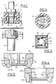
- FIG. 1 there is shown a set of tools for the realization of an assembly point, according to the invention.
- These tools include a tool 1 provided with a shank 2 to allow its attachment to a mandrel of a machine.
- Tool 1 has a shoulder 3 intended to receive a support stop 4 for a blank holder 5.
- the blank holder 5 is constituted by a block of rubber or plastic material shaped so as to have a circular opening 6 whose edges cooperate, on the one hand, with the bearing stop 4 and, on the other hand, with a shoulder 7 of the tool.
- the tool 1 is terminated by the active part of the punch 8 which has four grooves 9 which extend parallel to the longitudinal axis of the tool and which are regularly offset by 90 ° between them.
- the active part of the punch 8 has, on the side of the free end, a cylindrical part 8 a connected to the small base of a truncated cone 8 b , the large base of which is adjacent to the shoulder 7.
- the bottom of the grooves 9 is rounded and these are open at the free end of the punch 8.
- the punch 8 is intended to cooperate with a matrix 10 which includes four shells 11 which rest by their underside on a guide surface 12 of the tool 13.
- the guide surface 12 and the underside shells 10 are perfectly machined so that the shells 10 can slide freely on said surface 12.
- the tool 13 includes an anvil 14 against the lateral surface of which the shells abut 11.
- a cage 16 which constitutes a stop limiting the sliding of the shells 11 and which has holes 17 for guiding fingers 18 secured to the shells 11.
- the shells 11 have a groove 20 in which is housed a tension spring 21 in the form of a ring closed.
- References 23 and 24 designate two sheets, for example, aluminum sheets.
- the free end of the shells 11 is rounded which has the advantage, when formation of the assembly point, avoid when the shells move apart that the sheet 24 is marked. Indeed, thanks to the rounded ends, the shells when they deviate only on the sheet 24 on one point and no projecting part is in contact with said sheet.
- the rounding is carried out so that the free edge shells 11 located on the side of the internal lateral edge cooperating with the lateral surface of the anvil 14 either located at a distance from the upper guide surface 12 to that separating said guide surface from the free edge of each shell 11 located on the side of the lateral surface external of it.
- Tool 1 is lowered so that the blank holder 5 blocks said sheets, the punch 8 deforming by cold stamping said sheets to form the point assembly.
- the grooves 9 of the punch 8 forms in the cavity 26 four beads 35 which extend parallel to each other from the bottom from the cavity 26 towards the free edge of the latter.
- Figure 4 shows a section of an assembly point made with a classic punch and we carried over in this figure the same references as those used to designate different corresponding parts of the point assembly of figure 5, but assigned the letter "at”.
- the thickness "L" of the sheet 23 a in the part situated above the flaring 32 a and comprised between the projection 33 a and the cavity 26 a is smaller than for the other parts.
- the formation of the beads 35 allows the right of these beads to increase the thickness "L” and thus strengthen the assembly point.
Landscapes
- Engineering & Computer Science (AREA)
- Mechanical Engineering (AREA)
- Shaping Metal By Deep-Drawing, Or The Like (AREA)
- Stackable Containers (AREA)
- Meat, Egg Or Seafood Products (AREA)
- Perforating, Stamping-Out Or Severing By Means Other Than Cutting (AREA)
Claims (8)
- Punktverbindung von Blechen durch Kaltfließverformen, wobei man in zumindest zwei übereinanderliegenden Blechen (23 und 24) gleichzeitig mit Hilfe eines Stempels und einer Matrize zwei Tiefungen so herstellt, daß in jedem der Bleche von einer Seite her ein Hohlraum (26, 27) und auf der anderen Seite ein Vorsprung (33, 34) gebildet werden, wobei der Vorsprung (33) des ersten Bleches (23) in den Hohlraum (27) des zweiten Bleches (24) eingefügt ist, der genannte Hohlraum (27) des zweiten Bleches (24) in der Nähe seines Bodens (30) eine Erweiterung (31) besitzt und der Vorsprung (33) des ersten Bleches eine Ausbauchung (32) aufweist, die in der genannten Erweiterung (31) angeordnet ist, dadurch gekennzeichnet, daß der Hohlraum (26) des ersten Bleches (23) eine Reihe von Wülsten (35) aufweist, die sich im wesentlichen parallel vom Boden des genannten Hohlraumes gegen den freien Rand desselben erstrecken.
- Punktverbindung nach Anspruch 1, dadurch gekennzeichnet, daß die Anzahl der Wülste (35) vier beträgt und sie in regelmäßigen Abständen voneinander angeordnet sind.
- Werkzeuge zum Herstellen der Punktverbindung nach Anspruch 1, mit einem Stempel (8) mit einem Niederhalter (5), mit einer Matrize (10), die einen Amboß (14) aufweist, gegen den Schalen (11) federnd angelegt sind, die auf einer Führungsfläche (12) beweglich und in ihrer Verschiebebewegung durch einen Anschlag (16) begrenzt sind, dadurch gekennzeichnet, daß der Stempel (8) Rillen (9) aufweist, die sich parallel zur Längsachse des genannten Stempels (8) erstrecken und an dessen freiem Ende offen sind.
- Werkzeuge nach Anspruch 3, dadurch gekennzeichnet, daß der Stempel (8) eine kegelstumpfförmige Form besitzt.
- Werkzeuge nach Anspruch 3, dadurch gekennzeichnet, daß der Stempel (8) in einem zylindrischen Teil (8a) endigt, der mit der kleinen Basis eines Kegelstumpfes (8b) verbunden ist.
- Werkzeuge nach Anspruch 3, dadurch gekennzeichnet, daß die Rillen (9) in regelmäßigen Winkelabständen zueinander versetzt sind.
- Werkzeuge nach Anspruch 3, dadurch gekennzeichnet, daß die freien Enden der Schalen (11) abgerundet sind.
- Werkzeuge nach Anspruch 7, dadurch gekennzeichnet, daß die freien Enden der Schalen (11) so abgerundet sind, daß der freie Rand der genannten Schalen (11) auf deren mit dem Amboß (14) zusammenwirkender Seite von der Führungsfläche einen Abstand hat, der größer ist als der betreffende Abstand an dem der seitlichen Außenwand benachbarten freien Rand der Schalen (11).
Priority Applications (4)
| Application Number | Priority Date | Filing Date | Title |
|---|---|---|---|
| FR929207191A FR2692181B1 (fr) | 1992-06-15 | 1992-06-15 | Nouveau point d'assemblage de tôles par fluage à froid et outils pour la réalisation dudit point d'assemblage. |
| DE69319601T DE69319601T2 (de) | 1992-06-15 | 1993-12-08 | Punktverbindung von Blechen durch Kaltfliessen und Werkzeuge zur Herstellung dieser Verbindung |
| ES93402964T ES2121969T3 (es) | 1992-06-15 | 1993-12-08 | Conexion mediante punto de union para chapas por extrusion en frio y herramientas para producir esta conexion. |
| EP93402964A EP0657232B1 (de) | 1992-06-15 | 1993-12-08 | Punktverbindung von Blechen durch Kaltfliessen und Werkzeuge zur Herstellung dieser Verbindung |
Applications Claiming Priority (2)
| Application Number | Priority Date | Filing Date | Title |
|---|---|---|---|
| FR929207191A FR2692181B1 (fr) | 1992-06-15 | 1992-06-15 | Nouveau point d'assemblage de tôles par fluage à froid et outils pour la réalisation dudit point d'assemblage. |
| EP93402964A EP0657232B1 (de) | 1992-06-15 | 1993-12-08 | Punktverbindung von Blechen durch Kaltfliessen und Werkzeuge zur Herstellung dieser Verbindung |
Publications (2)
| Publication Number | Publication Date |
|---|---|
| EP0657232A1 EP0657232A1 (de) | 1995-06-14 |
| EP0657232B1 true EP0657232B1 (de) | 1998-07-08 |
Family
ID=26134755
Family Applications (1)
| Application Number | Title | Priority Date | Filing Date |
|---|---|---|---|
| EP93402964A Expired - Lifetime EP0657232B1 (de) | 1992-06-15 | 1993-12-08 | Punktverbindung von Blechen durch Kaltfliessen und Werkzeuge zur Herstellung dieser Verbindung |
Country Status (4)
| Country | Link |
|---|---|
| EP (1) | EP0657232B1 (de) |
| DE (1) | DE69319601T2 (de) |
| ES (1) | ES2121969T3 (de) |
| FR (1) | FR2692181B1 (de) |
Citations (1)
| Publication number | Priority date | Publication date | Assignee | Title |
|---|---|---|---|---|
| GB2189175A (en) * | 1986-04-17 | 1987-10-21 | Btm Corp | Apparatus for joining sheet material |
Family Cites Families (3)
| Publication number | Priority date | Publication date | Assignee | Title |
|---|---|---|---|---|
| US3771216A (en) * | 1971-10-27 | 1973-11-13 | Johnson Die & Eng Co | Method and tooling for extruding a closed end rivet |
| DE3131301A1 (de) * | 1981-08-07 | 1983-02-24 | Siemens AG, 1000 Berlin und 8000 München | "vorrichtung zum verbinden mindestens zweier duennwandiger werkstuecke durch ein scher-quetsch-verfahren" |
| DE3923182A1 (de) * | 1989-07-13 | 1991-01-24 | Fraunhofer Ges Forschung | Vorrichtung zum verbinden von plattenfoermigen bauteilen |
-
1992
- 1992-06-15 FR FR929207191A patent/FR2692181B1/fr not_active Expired - Lifetime
-
1993
- 1993-12-08 EP EP93402964A patent/EP0657232B1/de not_active Expired - Lifetime
- 1993-12-08 ES ES93402964T patent/ES2121969T3/es not_active Expired - Lifetime
- 1993-12-08 DE DE69319601T patent/DE69319601T2/de not_active Expired - Lifetime
Patent Citations (1)
| Publication number | Priority date | Publication date | Assignee | Title |
|---|---|---|---|---|
| GB2189175A (en) * | 1986-04-17 | 1987-10-21 | Btm Corp | Apparatus for joining sheet material |
Also Published As
| Publication number | Publication date |
|---|---|
| FR2692181B1 (fr) | 1994-09-02 |
| DE69319601T2 (de) | 1999-05-20 |
| EP0657232A1 (de) | 1995-06-14 |
| FR2692181A1 (fr) | 1993-12-17 |
| ES2121969T3 (es) | 1998-12-16 |
| DE69319601D1 (de) | 1998-08-13 |
Similar Documents
| Publication | Publication Date | Title |
|---|---|---|
| CA2656368C (fr) | Support pour une serie d'outils | |
| EP0649355B1 (de) | Verbesserungen an werkzeugen zur erzeugung von befestigungspunkten an blechen durch kaltformung | |
| CH650189A5 (fr) | Assemblage a lame de rasoir. | |
| FR2542224A1 (fr) | Matrice de retenue d'ebauche | |
| EP0869862B1 (de) | Verstellbare zange | |
| EP0657232B1 (de) | Punktverbindung von Blechen durch Kaltfliessen und Werkzeuge zur Herstellung dieser Verbindung | |
| FR2714132A1 (fr) | Dispositif de fixation d'attaches de courroie constituées d'agrafes disposées en rangée sur les extrémités de courroies de transport. | |
| CA2031859C (fr) | Procede et dispositif d'emboutissage de recipients de forme tronconique, et recipient ainsi embouti | |
| EP3242757B1 (de) | Werkzeug und verfahren zum formen einer kante eines stanzstückes mit unterschnittrückführung | |
| FR2937568A1 (fr) | Procede de fabrication d'une piece de boulonnerie, outil pour la mise en oeuvre du procede, dispositif de vissage et de devissage d'une telle piece de boulonnerie | |
| EP0246449A1 (de) | Einheit umfassend ein Uhrgehäuseelement und ein Armband | |
| FR3019765A1 (fr) | Agencement de serre flan dans un outil d'emboutissage | |
| EP1123758B1 (de) | Biegevorrichtung für eine Presse | |
| EP3442852B1 (de) | Anordnung einer abschirmung und eines karosserieelements eines kraftfahrzeugs, insbesondere eines karosserieelements aus blech | |
| EP0664170B1 (de) | Verbesserungen an Werkzeugen zum Herstellen von Punktverbindungen an Platten | |
| FR3005880A1 (fr) | Procede d'emboutissage d'une piece, notamment de carrosserie de vehicule automobile, a prise de pince amelioree | |
| CH643471A5 (fr) | Ecrou a riveter et outil pour sa pose. | |
| FR2709111A1 (fr) | Barquette métallique notamment en acier à deux compartiments et procédé de fabrication de ce type de barquettes. | |
| BE905854R (fr) | Module de systeme de construction. | |
| WO2007099221A1 (fr) | Bijou circulaire a anneaux tournants et son procede de fabrication | |
| FR2749525A1 (fr) | Outillage pour former des signes dans une plaque signaletique du type double | |
| EP4008449A1 (de) | Stauchwerkzeug und entsprechende anwendung | |
| FR3146609A1 (fr) | Procede de fabrication d’un flasque de maintien d’une bague exterieure d’un roulement | |
| FR3011755A1 (fr) | Presseur et outillage de mise a forme de rebord en saillie en peripherie d'un ajour d'un embouti | |
| FR2776219A1 (fr) | Arbre metallique destine a recevoir une piece surmoulee ou rapportee et ensemble ainsi obtenu |
Legal Events
| Date | Code | Title | Description |
|---|---|---|---|
| PUAI | Public reference made under article 153(3) epc to a published international application that has entered the european phase |
Free format text: ORIGINAL CODE: 0009012 |
|
| AK | Designated contracting states |
Kind code of ref document: A1 Designated state(s): DE ES GB IT |
|
| 17P | Request for examination filed |
Effective date: 19951207 |
|
| 17Q | First examination report despatched |
Effective date: 19970403 |
|
| GRAG | Despatch of communication of intention to grant |
Free format text: ORIGINAL CODE: EPIDOS AGRA |
|
| GRAG | Despatch of communication of intention to grant |
Free format text: ORIGINAL CODE: EPIDOS AGRA |
|
| GRAH | Despatch of communication of intention to grant a patent |
Free format text: ORIGINAL CODE: EPIDOS IGRA |
|
| GRAH | Despatch of communication of intention to grant a patent |
Free format text: ORIGINAL CODE: EPIDOS IGRA |
|
| GRAA | (expected) grant |
Free format text: ORIGINAL CODE: 0009210 |
|
| AK | Designated contracting states |
Kind code of ref document: B1 Designated state(s): DE ES GB IT |
|
| REF | Corresponds to: |
Ref document number: 69319601 Country of ref document: DE Date of ref document: 19980813 |
|
| GBT | Gb: translation of ep patent filed (gb section 77(6)(a)/1977) |
Effective date: 19981008 |
|
| REG | Reference to a national code |
Ref country code: ES Ref legal event code: FG2A Ref document number: 2121969 Country of ref document: ES Kind code of ref document: T3 |
|
| PLBE | No opposition filed within time limit |
Free format text: ORIGINAL CODE: 0009261 |
|
| STAA | Information on the status of an ep patent application or granted ep patent |
Free format text: STATUS: NO OPPOSITION FILED WITHIN TIME LIMIT |
|
| 26N | No opposition filed | ||
| REG | Reference to a national code |
Ref country code: GB Ref legal event code: IF02 |
|
| PGFP | Annual fee paid to national office [announced via postgrant information from national office to epo] |
Ref country code: GB Payment date: 20121220 Year of fee payment: 20 Ref country code: IT Payment date: 20121217 Year of fee payment: 20 Ref country code: ES Payment date: 20121221 Year of fee payment: 20 |
|
| PGFP | Annual fee paid to national office [announced via postgrant information from national office to epo] |
Ref country code: DE Payment date: 20121219 Year of fee payment: 20 |
|
| REG | Reference to a national code |
Ref country code: DE Ref legal event code: R071 Ref document number: 69319601 Country of ref document: DE |
|
| REG | Reference to a national code |
Ref country code: DE Ref legal event code: R071 Ref document number: 69319601 Country of ref document: DE |
|
| REG | Reference to a national code |
Ref country code: GB Ref legal event code: PE20 Expiry date: 20131207 |
|
| PG25 | Lapsed in a contracting state [announced via postgrant information from national office to epo] |
Ref country code: DE Free format text: LAPSE BECAUSE OF EXPIRATION OF PROTECTION Effective date: 20131210 Ref country code: GB Free format text: LAPSE BECAUSE OF EXPIRATION OF PROTECTION Effective date: 20131207 |
|
| REG | Reference to a national code |
Ref country code: ES Ref legal event code: FD2A Effective date: 20140925 |
|
| PG25 | Lapsed in a contracting state [announced via postgrant information from national office to epo] |
Ref country code: ES Free format text: LAPSE BECAUSE OF EXPIRATION OF PROTECTION Effective date: 20131209 |