EP0656578A2 - Système d'ordinateur portable - Google Patents
Système d'ordinateur portable Download PDFInfo
- Publication number
- EP0656578A2 EP0656578A2 EP94308629A EP94308629A EP0656578A2 EP 0656578 A2 EP0656578 A2 EP 0656578A2 EP 94308629 A EP94308629 A EP 94308629A EP 94308629 A EP94308629 A EP 94308629A EP 0656578 A2 EP0656578 A2 EP 0656578A2
- Authority
- EP
- European Patent Office
- Prior art keywords
- signal
- battery
- computer system
- power
- control unit
- Prior art date
- Legal status (The legal status is an assumption and is not a legal conclusion. Google has not performed a legal analysis and makes no representation as to the accuracy of the status listed.)
- Granted
Links
Images


Classifications
-
- G—PHYSICS
- G06—COMPUTING; CALCULATING OR COUNTING
- G06F—ELECTRIC DIGITAL DATA PROCESSING
- G06F1/00—Details not covered by groups G06F3/00 - G06F13/00 and G06F21/00
- G06F1/26—Power supply means, e.g. regulation thereof
- G06F1/28—Supervision thereof, e.g. detecting power-supply failure by out of limits supervision
-
- G—PHYSICS
- G06—COMPUTING; CALCULATING OR COUNTING
- G06F—ELECTRIC DIGITAL DATA PROCESSING
- G06F1/00—Details not covered by groups G06F3/00 - G06F13/00 and G06F21/00
- G06F1/26—Power supply means, e.g. regulation thereof
- G06F1/30—Means for acting in the event of power-supply failure or interruption, e.g. power-supply fluctuations
Definitions
- This invention relates to portable computer systems and more particularly to low battery detection and indicator circuitry for portable computer systems. This invention further relates to power management units for portable computer systems.
- the battery monitors may indicate when the battery capacity, as inferred by the voltage across the battery, decreases below a certain threshold, or may indicate the capacity of the battery over a broad range of possible values.
- the battery capacity is diminished to a critical point, damage to the battery and other system components may occur.
- the computer is powered-on, the user may receive the indication of the low battery condition in real time and may accordingly power-down the system to recharge the battery.
- the computer is in a powered-off state or in a power-conserving suspend state (during which, for example, the CPU clock signal and the system clock signal may be stopped), the user may be unaware of a low battery condition.
- the user subsequently attempts to turn on the computer system or the system attempts to restart the CPU and system clock signals, the battery will be drained even further. This can damage the battery and other system components.
- a computer system that employs a disable technique warns the user of a low battery condition that exists when the user attempts to power-on the computer, and prevents power from being applied to the primary portion of the computer system.
- a battery monitor is provided for monitoring the voltage across the battery, and for asserting a control signal when the battery voltage drops below a certain threshold value.
- a control unit receives the control signal and accordingly prevents power from being applied to a primary computer subsystem when the computer system is turned on. Instead, when the user attempts to turn on the computer system when the low battery-capacity condition exists, the control unit causes a pulse generator to generate a signal that drives a speaker. An audible indication of the low power condition is thereby produced. In accordance, the user is alerted to the low battery condition, while further power is prevented from being depleted from the battery as a result of applying power to the primary computer subsystem.
- a power management unit having a ready state and a power-conserving suspend state.
- a CPU clock signal and a system clock signal are driven at maximum frequencies.
- the CPU and system clock signals are either reduced in frequencies or are entirely stopped. If a low battery condition exists, the power management unit is forced to remain in the suspend state regardless of subsequent system activity. An audible indication of the low battery condition is instead produced to alert the user of the low battery condition.
- the present invention contemplates a portable computer system comprising a primary computer subsystem, a battery pack, and a power switch for providing power from the battery pack to the primary computer subsystem.
- the computer system further includes a battery monitor unit for monitoring the capacity of the battery pack and capable of generating a control signal indicative of a low battery condition.
- the computer system finally includes a control unit coupled to the battery monitor unit, wherein the control unit is capable of preventing power from being provided to the primary computer subsystem through the power switch when the control signal is asserted, and wherein the control unit is capable of generating an indicator signal for activating a user indicator when the control signal is asserted and when the power switch is closed.
- the invention further contemplates a power management unit for a portable computer system comprising a battery monitor for monitoring a capacity level of a battery and capable of generating a control signal indicative of a low battery condition.
- the power management unit also includes a system monitor for monitoring a circuit portion of the computer system and capable of asserting a suspend state signal when the circuit portion is inactive and capable of deasserting the suspend state signal when the circuit portion is active.
- a clock control unit is coupled to the system monitor and is capable of asserting a clock suspend signal in response to an assertion of the suspend state signal.
- the clock suspend signal is for controlling the frequency of a clock signal.
- the system monitor asserts the suspend state signal when the control signal is asserted, and is prevented from deasserting the suspend state signal when the control signal is asserted.
- the invention finally contemplates a power management method for a portable computer system comprising the steps of monitoring a circuit portion of the computer system, entering a suspend state if the circuit portion is inactive, reducing the frequency of a clock signal in response to the step of entering the suspend state, monitoring the capacity of a battery, and preventing the computer system from returning to the ready state if the capacity of the battery is below a predetermined threshold value.
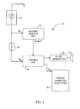
- FIG. 1 is a block diagram of a portable computer system 10 that employs a disable technique during low battery conditions according to the present invention.
- computer system 10 includes a battery pack 12 coupled to a battery monitor unit 14 and a power switch 16.
- a control unit 18 is coupled to battery monitor 14 and to power switch 16.
- Control unit 18 includes a pair of output lines, one of which is coupled to a pulse generator 20 and the other of which is coupled to a primary computer subsystem 22.
- a speaker 24 is finally shown coupled to pulse generator 20.
- Primary computer subsystem 22 is representative of a variety of major functional subunits of computer system 10.
- primary computer subsystem 22 includes a system microprocessor, a system memory, and a system display, among other things.
- the nominal voltage produced by battery pack 12 is 12 volts.
- battery monitor unit 14 detects the nominal voltage at an input line and accordingly deas- serts (low) an indicator signal labeled "VLBATT".
- VLBATT deasserted low
- control unit 18 allows battery power to be coupled to the primary computer subsystem 22 when power switch 16 is closed.
- control unit 18 responsively prevents power from being applied to primary computer subsystem 22 and generates a control signal that is received by pulse generator 20.
- pulse generator 20 produces a pulsed signal, as illustrated in the waveform diagram of Figure 2.
- the pulsed signal generated by pulse generator 20 drives speaker 24, which accordingly produces an audible tone. It is noted that in the embodiment of Figure 1, the pulse signal generated by pulse generator 20 induces a beeping sound consisting of three 1 second tones.
- battery monitor unit 14 again detects the low battery condition by monitoring the voltage V b across the battery pack 12. When the battery voltage V b falls below the predetermined threshold value, the battery monitor unit 14 again asserts the VLBATT signal. If the user subsequently attempts to power-on the primary computer subsystem 22 by closing power switch 16 when the VLBATT signal is asserted, control unit 18 prevents power from being applied to the primary computer subsystem 22. When the power switch 16 is closed, the control unit 18 Instead provides a control signal to pulse generator 20, thereby causing the generation of the pulsed signal (as illustrated in Figure 2) that causes sound to be produced from speaker 24.
- FIG. 3 illustrates one embodiment of control unit 18.
- the control unit 18 of Figure 3 includes a pair of field effect transistors 30 and 32, an inverter 34, and a one-shot circuit 36.
- transistor 30 when the VLBATT signal is deasserted low, transistor 30 is turned on and transistor 32 is turned off. Accordingly, the battery voltage V b is provided to primary computer subsystem 22.
- the VLBATT signal When the VLBATT signal is asserted high, transistor 30 is turned off, and transistor 32 is turned on. Accordingly, the battery voltage is disconnected from the primary computer subsystem 22 and one-shot circuit 36 provides a signal to pulse generator 20 that causes the production of an audible indication of the low battery condition.
- an external indication of a critically low battery condition of battery pack 12 is provided to the system user even if the primary computer subsystem 22 is powered-down.
- the external indicator is generated when the user attempts to power the computer system on. Since power cannot be applied to primary computer subsystem 22 when the low battery condition exists, further depletion of battery power is prevented.
- the computer system 100 includes a microprocessor (CPU) 102, a memory controller 104, and a disk controller 106 coupled to a clock generator 108.
- the computer system 100 further includes a power management unit 110, a speaker 112, and a battery pack 114.
- Clock generator 108 generates a CPU clock signal that is provided to microprocessor 102 and a system clock signal that is provided to memory controller 104 and to disk controller 106, among other things. It is noted that the CPU clock signal may have a different frequency from the system clock signal. For example, in one embodiment, the CPU clock signal has a maximum frequency of 80 MHz and the system clock signal has a maximum frequency of 40MHz.
- Power management unit 110 includes a system monitor 120 coupled to an AC detect unit 122 and to a clock control unit 124.
- System monitor 120 is further coupled to a pulse generator 126 and to a battery monitor 128.
- Microprocessor 102, memory controller 104, and disk controller 106 are coupled to a CPU local bus (not shown). It is noted that computer system 100 may include a variety of additional peripheral devices. It is further noted that battery pack 114 provides power to microprocessor 102, memory controller 104, and disk controller 106; however, the specific connections from battery pack 114 to microprocessor 102, memory controller 104, and disk controller 106 have been omitted from the drawing in the interest of simplicity and clarity. It is also noted that AC power may be provided to computer system 100 during certain times to provide an alternate power source.
- system monitor 120 monitors various subsystems of the computer system 100 such as the microprocessor 102, memory controller 104, and disk controller 106, among other things.
- system monitor 120 detects activity of the microprocessor and other system peripherals by detecting signal activity on the CPU local bus and/or a peripheral bus.
- power management 110 is in a "ready" state during which the clock generator 108 drives the CPU clock signal and the system clock signal at their maximum frequencies.
- system monitor 120 could be employed within power management unit 110, and exemplary system monitors are described in numerous publications of the known prior art. For example, an exemplary system monitor that detects inactive circuit portions of a computer system is described within U.S. patent number 5,167,024 issued November 24, 1992 to Smith et al. This patent is incorporated herein by reference in its entirety.
- system monitor 120 When system monitor 120 determines that the microprocessor 102, the system memory controller 104, and the disk controller 106 are inactive, system monitor 120 enters a "suspend" state during which a control signal, identified herein as the "Suspend State Signal", is asserted.
- the Suspend State Signal is provided to clock control unit 124 which accordingly asserts a control signal labelled the “Clock Suspend Signal” that is received by clock generator 108.
- the clock generator 108 either reduces the frequencies of the CPU clock signal and the system clock signal to, for example, 5 MHz and 2 MHz, respectively, or stops the CPU clock signal and the system clock signal completely (i.e., 0 MHz).
- overall power consumption of the computer system is significantly reduced.
- battery monitor 128 asserts the signal VLBATT. Similar to the previously described embodiment of Figure 1, when the system monitor 120 receives the asserted VLBATT signal, a control signal is provided to pulse generator 126 which accordingly causes an audible sound to be produced by speaker 112. At the same time, system monitor 120 is forced to enter the suspend state. Thus, the suspend state signal is asserted such that the clock control unit 124 causes clock generator 108 to either reduce the frequencies of or stop the CPU and system clock signals.
- system monitor 120 If the power management unit 110 is in the suspend state and a system activity occurs that would normally cause system monitor 120 to enter the ready state, and if the low battery signal VLBATT is asserted, system monitor 120 is prevented from entering the ready state. Depending upon the type of system activity, an audible indication alerting the user of the low battery condition is instead produced. Accordingly, the CPU clock signal and the system clock signal are kept at their low frequencies or are prevented from being restarted and, further significant power dissipation from battery pack 114 is prevented.
- power management 110 may further be configured to control the application of power to microprocessor 102, memory controller 104, disk controller 106, among other things, in a similar manner.
- switch 16 is an electronic switch selectively controlled by system monitor 120 depending upon whether the system is in the ready or in the suspend state.
- the disable technique employed during low battery conditions as described herein may be used in conjunction with a variety of additional power management techniques.
- the disable technique may be employed in conjunction with the power management techniques taught within the co-pending, commonly assigned patent applications: "System Oscillator Gating Technique For Power Management Within a Computer System", by O'Brien, Serial No. , filed concurrently herewith; "Interrupt Controller With In-Service Indication", by MacDonald et al., Serial No. 08/125,336, filed September 22, 1993; and "Power Management Control Technique For Timer Tick Activity Within An Interrupt Driven Computer System", by O'Brien et al., Serial No. , filed November 23, 1993.
- These patent applications are incorporated herein by reference in their entirety.
Landscapes
- Engineering & Computer Science (AREA)
- Theoretical Computer Science (AREA)
- Physics & Mathematics (AREA)
- General Engineering & Computer Science (AREA)
- General Physics & Mathematics (AREA)
- Power Sources (AREA)
Applications Claiming Priority (2)
| Application Number | Priority Date | Filing Date | Title |
|---|---|---|---|
| US08/160,930 US5442794A (en) | 1993-12-01 | 1993-12-01 | Disable technique employed during low battery conditions within a portable computer system |
| US160930 | 1993-12-01 |
Publications (3)
| Publication Number | Publication Date |
|---|---|
| EP0656578A2 true EP0656578A2 (fr) | 1995-06-07 |
| EP0656578A3 EP0656578A3 (fr) | 1995-08-02 |
| EP0656578B1 EP0656578B1 (fr) | 2000-02-16 |
Family
ID=22579080
Family Applications (1)
| Application Number | Title | Priority Date | Filing Date |
|---|---|---|---|
| EP94308629A Expired - Lifetime EP0656578B1 (fr) | 1993-12-01 | 1994-11-23 | Système d'ordinateur portable |
Country Status (4)
| Country | Link |
|---|---|
| US (1) | US5442794A (fr) |
| EP (1) | EP0656578B1 (fr) |
| JP (1) | JPH07200110A (fr) |
| DE (1) | DE69423034D1 (fr) |
Cited By (6)
| Publication number | Priority date | Publication date | Assignee | Title |
|---|---|---|---|---|
| DE19529588A1 (de) * | 1995-08-11 | 1997-02-13 | Ibm | Datenverarbeitungssystem mit trennbaren Systemeinheiten |
| EP0895150A2 (fr) * | 1997-08-01 | 1999-02-03 | Pitney Bowes Inc. | Circuit de mise hors tension |
| EP0911938A2 (fr) * | 1997-10-21 | 1999-04-28 | NEC Corporation | Dispositif de commande marche/arrêt pour une unité d'alimentation d'énergie |
| EP0996050A2 (fr) * | 1998-10-19 | 2000-04-26 | Fujitsu Limited | Dispositif électronique |
| CN105809931A (zh) * | 2016-05-17 | 2016-07-27 | 合网络技术(北京)有限公司 | 遥控设备及智能设备 |
| US9552042B2 (en) | 2013-08-02 | 2017-01-24 | Blackberry Limited | Electronic device and method of detecting touches on a touch-sensitive display |
Families Citing this family (41)
| Publication number | Priority date | Publication date | Assignee | Title |
|---|---|---|---|---|
| US5933649A (en) * | 1994-06-20 | 1999-08-03 | Samsung Electronics Co., Ltd. | Method and device for controlling a CPU stop clock interrupt |
| US5587916A (en) * | 1994-08-15 | 1996-12-24 | B.E.L.-Tronics Limited | Low voltage sensing circuits for battery powered devices having a micro-processor |
| US5778239A (en) * | 1994-12-30 | 1998-07-07 | Compaq Computer Corporation | Computer real time clockpower supply circuit |
| JPH08331768A (ja) * | 1995-06-02 | 1996-12-13 | Internatl Business Mach Corp <Ibm> | バッテリの過放電保護回路 |
| FR2735870B1 (fr) * | 1995-06-21 | 1997-09-05 | Sgs Thomson Microelectronics | Mesure numerique relative de haute precision d'une tension |
| US5802379A (en) * | 1995-08-24 | 1998-09-01 | Norand Corporation | Battery depletion management in portable computing devices having PCMCIA card loading |
| US5991887A (en) | 1996-02-28 | 1999-11-23 | Dallas Semiconductor Corporation | Low power wake up circuitry, with internal power down of the wake up circuitry itself |
| US6691236B1 (en) * | 1996-06-03 | 2004-02-10 | Hewlett-Packard Development Company, L.P. | System for altering operation of a graphics subsystem during run-time to conserve power upon detecting a low power condition or lower battery charge exists |
| KR100278355B1 (ko) * | 1996-09-30 | 2001-01-15 | 윤종용 | 컴퓨터 시스템 및 이 컴퓨터 시스템의 제어 방법 |
| TW382670B (en) * | 1996-11-21 | 2000-02-21 | Hitachi Ltd | Low power processor |
| KR100233133B1 (ko) * | 1997-08-29 | 1999-12-01 | 윤종용 | 개인 정보 단말기의 효율적 전원관리 방법 |
| KR19990026189A (ko) * | 1997-09-23 | 1999-04-15 | 윤종용 | 바이오스 롬의 업데이트 방법 |
| GB9721360D0 (en) * | 1997-10-08 | 1997-12-10 | Transmatic Europ Limited | Rack unit |
| KR100561379B1 (ko) | 1999-01-08 | 2006-03-16 | 삼성전자주식회사 | 도킹 시스템의 전원공급장치 및 장애로부터 안전한 도킹 시스템 |
| US6523124B1 (en) * | 1999-04-23 | 2003-02-18 | Palm, Inc. | System and method for detection of an accessory device connection status |
| US6351820B1 (en) * | 1999-04-26 | 2002-02-26 | Abocom Systems, Inc. | PC card with automated drag and sleep function |
| US6425087B1 (en) * | 1999-05-28 | 2002-07-23 | Palm, Inc. | Method and apparatus for using residual energy in a battery-powered computer |
| US6510524B1 (en) * | 1999-08-23 | 2003-01-21 | Palm, Inc. | System for managing power of peripheral communications by automatically closing communications channel immediately after finishing a communication with a peripheral device |
| US6211652B1 (en) | 2000-02-04 | 2001-04-03 | Milwaukee Electric Tool Corporation | Discharge protection apparatus for a battery-powered device and a method of preventing overdischarge of a battery |
| US6622252B1 (en) | 2000-04-12 | 2003-09-16 | International Business Machines Corporation | Data storage device having selectable performance modes for use in dual powered portable devices |
| US6687839B1 (en) | 2000-05-31 | 2004-02-03 | Palmone, Inc. | Method and apparatus allowing a battery to regain charge in a handheld device without an applied external charge while still supplying power selected designated components |
| US6708280B1 (en) | 2000-05-31 | 2004-03-16 | Palmone, Inc. | Method and apparatus for allowing a battery to preserve charge in a handheld device without an supplying unregulated voltage to selected internal components |
| US6799279B1 (en) * | 2000-06-21 | 2004-09-28 | Matsushita Electric Industrial Co., Ltd. | Method and apparatus for stopping supply of power to a specific function for playing contents stored on media in response to a low battery level |
| US7041055B2 (en) * | 2002-10-07 | 2006-05-09 | Mark LoGuidice | Instruments and methods for use in laparoscopic surgery |
| JP3879494B2 (ja) * | 2001-11-22 | 2007-02-14 | 日立工機株式会社 | 電池パック |
| KR20030057852A (ko) * | 2001-12-29 | 2003-07-07 | 삼성전자주식회사 | 휴대용 컴퓨터 및 그 제어방법 |
| US7114086B2 (en) * | 2002-01-04 | 2006-09-26 | Ati Technologies, Inc. | System for reduced power consumption by monitoring instruction buffer and method thereof |
| US7051236B2 (en) * | 2002-06-13 | 2006-05-23 | Dell Products L.P. | Wirelessly network-connected, battery-powered information handling system featuring prevention of data corruption after wake-up by a network event |
| US8525469B1 (en) * | 2003-07-03 | 2013-09-03 | Battery-Free Outdoors, Llc | System and method using capacitors to power a camera having a motion sensor |
| US7538762B2 (en) * | 2003-09-30 | 2009-05-26 | Intel Corporation | Switching display update properties upon detecting a power management event |
| US7392099B2 (en) * | 2003-12-12 | 2008-06-24 | Hewlett-Packard Development Company, L.P. | System and method for power management when an operating voltage is between two thresholds |
| ITMI20041113A1 (it) * | 2004-06-01 | 2004-09-01 | Antibioticos Spa | Processo per la sintesi della talidomide |
| JP2006101041A (ja) * | 2004-09-28 | 2006-04-13 | Fujitsu Ltd | 携帯電話機 |
| US7836216B2 (en) * | 2005-08-23 | 2010-11-16 | Palm, Inc. | Connector system for supporting multiple types of plug carrying accessory devices |
| KR100736079B1 (ko) * | 2005-09-07 | 2007-07-06 | 삼성전자주식회사 | 휴대용 기기의 전원 관리 장치 및 방법 |
| US7734841B2 (en) * | 2006-06-30 | 2010-06-08 | Palm, Inc. | System and method for providing serial bus connectivity |
| FI20065783A0 (sv) * | 2006-12-08 | 2006-12-08 | Nokia Corp | Signalfördistorsion i radiosändare |
| US7844844B2 (en) * | 2007-07-20 | 2010-11-30 | Dell Products L.P. | System and method for reserving information handling system battery charge to perform diagnostics |
| US8862924B2 (en) | 2011-11-15 | 2014-10-14 | Advanced Micro Devices, Inc. | Processor with power control via instruction issuance |
| CN103377108A (zh) * | 2012-04-28 | 2013-10-30 | 鸿富锦精密工业(武汉)有限公司 | 异常报警系统及方法 |
| US9335808B2 (en) * | 2013-03-08 | 2016-05-10 | Intel Corporation | Indicating critical battery status in mobile devices |
Citations (2)
| Publication number | Priority date | Publication date | Assignee | Title |
|---|---|---|---|---|
| EP0504007A2 (fr) * | 1991-03-08 | 1992-09-16 | Fujitsu Limited | Unité alimentée par batterie |
| EP0565914A1 (fr) * | 1992-04-15 | 1993-10-20 | International Business Machines Corporation | Système de gestion répartie de l'énergie dans des ordinateurs portables |
Family Cites Families (8)
| Publication number | Priority date | Publication date | Assignee | Title |
|---|---|---|---|---|
| JPS5710824A (en) * | 1980-06-25 | 1982-01-20 | Canon Inc | Recording system electronic apparatus |
| JPS6363819U (fr) * | 1986-10-14 | 1988-04-27 | ||
| JP2684658B2 (ja) * | 1987-11-30 | 1997-12-03 | セイコーエプソン株式会社 | 電池駆動可能な電子機器 |
| US4980836A (en) * | 1988-10-14 | 1990-12-25 | Compaq Computer Corporation | Apparatus for reducing computer system power consumption |
| US5167024A (en) * | 1989-09-08 | 1992-11-24 | Apple Computer, Inc. | Power management for a laptop computer with slow and sleep modes |
| US5070357A (en) * | 1989-12-05 | 1991-12-03 | Nikon Corporation | Battery check device for cameras |
| US5369771A (en) * | 1991-12-23 | 1994-11-29 | Dell U.S.A., L.P. | Computer with transparent power-saving manipulation of CPU clock |
| GB2264794B (en) * | 1992-03-06 | 1995-09-20 | Intel Corp | Method and apparatus for automatic power management in a high integration floppy disk controller |
-
1993
- 1993-12-01 US US08/160,930 patent/US5442794A/en not_active Expired - Lifetime
-
1994
- 1994-11-23 DE DE69423034T patent/DE69423034D1/de not_active Expired - Lifetime
- 1994-11-23 EP EP94308629A patent/EP0656578B1/fr not_active Expired - Lifetime
- 1994-11-30 JP JP6296545A patent/JPH07200110A/ja active Pending
Patent Citations (2)
| Publication number | Priority date | Publication date | Assignee | Title |
|---|---|---|---|---|
| EP0504007A2 (fr) * | 1991-03-08 | 1992-09-16 | Fujitsu Limited | Unité alimentée par batterie |
| EP0565914A1 (fr) * | 1992-04-15 | 1993-10-20 | International Business Machines Corporation | Système de gestion répartie de l'énergie dans des ordinateurs portables |
Cited By (10)
| Publication number | Priority date | Publication date | Assignee | Title |
|---|---|---|---|---|
| DE19529588A1 (de) * | 1995-08-11 | 1997-02-13 | Ibm | Datenverarbeitungssystem mit trennbaren Systemeinheiten |
| DE19529588C2 (de) * | 1995-08-11 | 1998-02-12 | Ibm | Datenverarbeitungssystem mit trennbaren Datenverarbeitungsgeräten |
| EP0895150A2 (fr) * | 1997-08-01 | 1999-02-03 | Pitney Bowes Inc. | Circuit de mise hors tension |
| EP0895150A3 (fr) * | 1997-08-01 | 2000-01-05 | Pitney Bowes Inc. | Circuit de mise hors tension |
| EP0911938A2 (fr) * | 1997-10-21 | 1999-04-28 | NEC Corporation | Dispositif de commande marche/arrêt pour une unité d'alimentation d'énergie |
| EP0911938A3 (fr) * | 1997-10-21 | 2000-09-13 | NEC Corporation | Dispositif de commande marche/arrêt pour une unité d'alimentation d'énergie |
| EP0996050A2 (fr) * | 1998-10-19 | 2000-04-26 | Fujitsu Limited | Dispositif électronique |
| EP0996050A3 (fr) * | 1998-10-19 | 2004-04-07 | Fujitsu Limited | Dispositif électronique |
| US9552042B2 (en) | 2013-08-02 | 2017-01-24 | Blackberry Limited | Electronic device and method of detecting touches on a touch-sensitive display |
| CN105809931A (zh) * | 2016-05-17 | 2016-07-27 | 合网络技术(北京)有限公司 | 遥控设备及智能设备 |
Also Published As
| Publication number | Publication date |
|---|---|
| EP0656578B1 (fr) | 2000-02-16 |
| DE69423034D1 (de) | 2000-03-23 |
| EP0656578A3 (fr) | 1995-08-02 |
| US5442794A (en) | 1995-08-15 |
| JPH07200110A (ja) | 1995-08-04 |
Similar Documents
| Publication | Publication Date | Title |
|---|---|---|
| US5442794A (en) | Disable technique employed during low battery conditions within a portable computer system | |
| US6085325A (en) | Method and apparatus for supporting power conservation operation modes | |
| JP3509232B2 (ja) | コンピュータシステムおよびその電力管理装置 | |
| KR970006390B1 (ko) | 컴퓨터 시스템의 전력 소모 감소 장치 | |
| US5504910A (en) | Power management unit including software configurable state register and time-out counters for protecting against misbehaved software | |
| US5664203A (en) | Peripheral device input-initiated resume system for combined hibernation system and back-up power supply for computer | |
| US5628020A (en) | System oscillator gating technique for power management within a computer system | |
| US6658577B2 (en) | Breathing status LED indicator | |
| KR100371181B1 (ko) | 휴대용 기기의 절전방법 | |
| KR920002245B1 (ko) | 밧데리 구동 휴대용 기기 | |
| CN110806794A (zh) | 存储系统的掉电保护方法、系统、计算机设备以及介质 | |
| KR101031117B1 (ko) | 저 전압 검출 시스템 | |
| GB2493257A (en) | Method for entering and exiting sleep mode in a graphics subsystem | |
| JPH07319590A (ja) | 携帯用情報処理機器の電源供給装置およびその駆動方法 | |
| JP3686232B2 (ja) | コンピュータシステムの周辺装置制御方法 | |
| WO2006071661A1 (fr) | Attenuation du bruit audio pour des transitions d'etat de puissance | |
| EP2843502A1 (fr) | Dispositif de traitement d'informations, procédé de traitement d'informations, et programme | |
| JPH113151A (ja) | 情報処理装置のハイバーネーション制御方法及びバッテリ駆動可能な電子機器 | |
| JP5455826B2 (ja) | 電源投入制御回路 | |
| US20040243826A1 (en) | Computer data protection control device | |
| US11966596B2 (en) | Method of power management using an expander for a storage system | |
| EP1391803A1 (fr) | Dispositif informatique, carte d'expansion, minicarte pci, circuit de mise en tension automatique, procede de demarrage automatique, et procede d'activation de signal | |
| JPH08313905A (ja) | 液晶ディスプレイ装置 | |
| JP3058070B2 (ja) | 情報処理装置 | |
| JPH044276Y2 (fr) |
Legal Events
| Date | Code | Title | Description |
|---|---|---|---|
| PUAI | Public reference made under article 153(3) epc to a published international application that has entered the european phase |
Free format text: ORIGINAL CODE: 0009012 |
|
| AK | Designated contracting states |
Kind code of ref document: A2 Designated state(s): BE DE DK ES FR GB GR IE IT LU NL PT SE |
|
| PUAL | Search report despatched |
Free format text: ORIGINAL CODE: 0009013 |
|
| AK | Designated contracting states |
Kind code of ref document: A3 Designated state(s): BE DE DK ES FR GB GR IE IT LU NL PT SE |
|
| 17P | Request for examination filed |
Effective date: 19950911 |
|
| 17Q | First examination report despatched |
Effective date: 19971229 |
|
| GRAG | Despatch of communication of intention to grant |
Free format text: ORIGINAL CODE: EPIDOS AGRA |
|
| GRAG | Despatch of communication of intention to grant |
Free format text: ORIGINAL CODE: EPIDOS AGRA |
|
| GRAH | Despatch of communication of intention to grant a patent |
Free format text: ORIGINAL CODE: EPIDOS IGRA |
|
| GRAH | Despatch of communication of intention to grant a patent |
Free format text: ORIGINAL CODE: EPIDOS IGRA |
|
| GRAA | (expected) grant |
Free format text: ORIGINAL CODE: 0009210 |
|
| AK | Designated contracting states |
Kind code of ref document: B1 Designated state(s): BE DE DK ES FR GB GR IE IT LU NL PT SE |
|
| PG25 | Lapsed in a contracting state [announced via postgrant information from national office to epo] |
Ref country code: NL Free format text: LAPSE BECAUSE OF FAILURE TO SUBMIT A TRANSLATION OF THE DESCRIPTION OR TO PAY THE FEE WITHIN THE PRESCRIBED TIME-LIMIT Effective date: 20000216 Ref country code: IT Free format text: LAPSE BECAUSE OF FAILURE TO SUBMIT A TRANSLATION OF THE DESCRIPTION OR TO PAY THE FEE WITHIN THE PRESCRIBED TIME-LIMIT;WARNING: LAPSES OF ITALIAN PATENTS WITH EFFECTIVE DATE BEFORE 2007 MAY HAVE OCCURRED AT ANY TIME BEFORE 2007. THE CORRECT EFFECTIVE DATE MAY BE DIFFERENT FROM THE ONE RECORDED. Effective date: 20000216 Ref country code: GR Free format text: LAPSE BECAUSE OF NON-PAYMENT OF DUE FEES Effective date: 20000216 Ref country code: FR Free format text: LAPSE BECAUSE OF FAILURE TO SUBMIT A TRANSLATION OF THE DESCRIPTION OR TO PAY THE FEE WITHIN THE PRESCRIBED TIME-LIMIT Effective date: 20000216 Ref country code: ES Free format text: THE PATENT HAS BEEN ANNULLED BY A DECISION OF A NATIONAL AUTHORITY Effective date: 20000216 Ref country code: BE Free format text: LAPSE BECAUSE OF FAILURE TO SUBMIT A TRANSLATION OF THE DESCRIPTION OR TO PAY THE FEE WITHIN THE PRESCRIBED TIME-LIMIT Effective date: 20000216 |
|
| REF | Corresponds to: |
Ref document number: 69423034 Country of ref document: DE Date of ref document: 20000323 |
|
| REG | Reference to a national code |
Ref country code: IE Ref legal event code: FG4D |
|
| PG25 | Lapsed in a contracting state [announced via postgrant information from national office to epo] |
Ref country code: SE Free format text: LAPSE BECAUSE OF FAILURE TO SUBMIT A TRANSLATION OF THE DESCRIPTION OR TO PAY THE FEE WITHIN THE PRESCRIBED TIME-LIMIT Effective date: 20000516 Ref country code: PT Free format text: LAPSE BECAUSE OF FAILURE TO SUBMIT A TRANSLATION OF THE DESCRIPTION OR TO PAY THE FEE WITHIN THE PRESCRIBED TIME-LIMIT Effective date: 20000516 Ref country code: DK Free format text: LAPSE BECAUSE OF FAILURE TO SUBMIT A TRANSLATION OF THE DESCRIPTION OR TO PAY THE FEE WITHIN THE PRESCRIBED TIME-LIMIT Effective date: 20000516 |
|
| PG25 | Lapsed in a contracting state [announced via postgrant information from national office to epo] |
Ref country code: DE Free format text: LAPSE BECAUSE OF FAILURE TO SUBMIT A TRANSLATION OF THE DESCRIPTION OR TO PAY THE FEE WITHIN THE PRESCRIBED TIME-LIMIT Effective date: 20000517 |
|
| EN | Fr: translation not filed | ||
| NLV1 | Nl: lapsed or annulled due to failure to fulfill the requirements of art. 29p and 29m of the patents act | ||
| PG25 | Lapsed in a contracting state [announced via postgrant information from national office to epo] |
Ref country code: LU Free format text: LAPSE BECAUSE OF NON-PAYMENT OF DUE FEES Effective date: 20001123 Ref country code: IE Free format text: LAPSE BECAUSE OF NON-PAYMENT OF DUE FEES Effective date: 20001123 |
|
| PLBE | No opposition filed within time limit |
Free format text: ORIGINAL CODE: 0009261 |
|
| STAA | Information on the status of an ep patent application or granted ep patent |
Free format text: STATUS: NO OPPOSITION FILED WITHIN TIME LIMIT |
|
| 26N | No opposition filed | ||
| REG | Reference to a national code |
Ref country code: IE Ref legal event code: MM4A |
|
| REG | Reference to a national code |
Ref country code: GB Ref legal event code: IF02 |
|
| REG | Reference to a national code |
Ref country code: GB Ref legal event code: 732E |
|
| PGFP | Annual fee paid to national office [announced via postgrant information from national office to epo] |
Ref country code: GB Payment date: 20121126 Year of fee payment: 19 |
|
| GBPC | Gb: european patent ceased through non-payment of renewal fee |
Effective date: 20131123 |
|
| PG25 | Lapsed in a contracting state [announced via postgrant information from national office to epo] |
Ref country code: GB Free format text: LAPSE BECAUSE OF NON-PAYMENT OF DUE FEES Effective date: 20131123 |