EP0656127B1 - Bohrloch-instrumentenkabel mit reduzierten durchmesser - Google Patents
Bohrloch-instrumentenkabel mit reduzierten durchmesser Download PDFInfo
- Publication number
- EP0656127B1 EP0656127B1 EP94917451A EP94917451A EP0656127B1 EP 0656127 B1 EP0656127 B1 EP 0656127B1 EP 94917451 A EP94917451 A EP 94917451A EP 94917451 A EP94917451 A EP 94917451A EP 0656127 B1 EP0656127 B1 EP 0656127B1
- Authority
- EP
- European Patent Office
- Prior art keywords
- cable
- layer
- reduced diameter
- optical fiber
- contact subassembly
- Prior art date
- Legal status (The legal status is an assumption and is not a legal conclusion. Google has not performed a legal analysis and makes no representation as to the accuracy of the status listed.)
- Expired - Lifetime
Links
- 239000013307 optical fiber Substances 0.000 claims description 45
- 239000012530 fluid Substances 0.000 claims description 29
- 238000007789 sealing Methods 0.000 claims description 24
- 239000012212 insulator Substances 0.000 claims description 23
- 230000001681 protective effect Effects 0.000 claims description 23
- 239000004020 conductor Substances 0.000 claims description 16
- 230000003287 optical effect Effects 0.000 claims description 15
- 238000000576 coating method Methods 0.000 claims description 8
- 239000010935 stainless steel Substances 0.000 claims description 8
- 229910001220 stainless steel Inorganic materials 0.000 claims description 8
- 239000011248 coating agent Substances 0.000 claims description 7
- 239000000463 material Substances 0.000 claims description 7
- BFKJFAAPBSQJPD-UHFFFAOYSA-N tetrafluoroethene Chemical group FC(F)=C(F)F BFKJFAAPBSQJPD-UHFFFAOYSA-N 0.000 claims description 6
- 238000002844 melting Methods 0.000 claims description 5
- 230000008018 melting Effects 0.000 claims description 5
- 239000000835 fiber Substances 0.000 claims description 4
- 229920001296 polysiloxane Polymers 0.000 claims description 4
- 239000010410 layer Substances 0.000 description 36
- 239000000523 sample Substances 0.000 description 23
- RYGMFSIKBFXOCR-UHFFFAOYSA-N Copper Chemical compound [Cu] RYGMFSIKBFXOCR-UHFFFAOYSA-N 0.000 description 12
- 239000010949 copper Substances 0.000 description 11
- 229910052802 copper Inorganic materials 0.000 description 11
- 210000002445 nipple Anatomy 0.000 description 7
- 238000000034 method Methods 0.000 description 5
- 239000004743 Polypropylene Substances 0.000 description 4
- 230000005611 electricity Effects 0.000 description 4
- -1 polypropylene Polymers 0.000 description 4
- 229920001155 polypropylene Polymers 0.000 description 4
- 238000001125 extrusion Methods 0.000 description 3
- 239000007789 gas Substances 0.000 description 3
- 229910001369 Brass Inorganic materials 0.000 description 2
- RWSOTUBLDIXVET-UHFFFAOYSA-N Dihydrogen sulfide Chemical compound S RWSOTUBLDIXVET-UHFFFAOYSA-N 0.000 description 2
- UFHFLCQGNIYNRP-UHFFFAOYSA-N Hydrogen Chemical compound [H][H] UFHFLCQGNIYNRP-UHFFFAOYSA-N 0.000 description 2
- 230000008901 benefit Effects 0.000 description 2
- 230000005540 biological transmission Effects 0.000 description 2
- 239000010951 brass Substances 0.000 description 2
- 238000005253 cladding Methods 0.000 description 2
- 238000004891 communication Methods 0.000 description 2
- 238000001514 detection method Methods 0.000 description 2
- 229920000840 ethylene tetrafluoroethylene copolymer Polymers 0.000 description 2
- 229920002313 fluoropolymer Polymers 0.000 description 2
- 229910052739 hydrogen Inorganic materials 0.000 description 2
- 239000001257 hydrogen Substances 0.000 description 2
- 229910000037 hydrogen sulfide Inorganic materials 0.000 description 2
- 238000003384 imaging method Methods 0.000 description 2
- 229910010272 inorganic material Inorganic materials 0.000 description 2
- 239000011147 inorganic material Substances 0.000 description 2
- 238000003780 insertion Methods 0.000 description 2
- 230000037431 insertion Effects 0.000 description 2
- 238000004519 manufacturing process Methods 0.000 description 2
- 239000000615 nonconductor Substances 0.000 description 2
- 229920000642 polymer Polymers 0.000 description 2
- WFKWXMTUELFFGS-UHFFFAOYSA-N tungsten Chemical compound [W] WFKWXMTUELFFGS-UHFFFAOYSA-N 0.000 description 2
- 239000010937 tungsten Substances 0.000 description 2
- 229910052721 tungsten Inorganic materials 0.000 description 2
- 230000000007 visual effect Effects 0.000 description 2
- OMIGHNLMNHATMP-UHFFFAOYSA-N 2-hydroxyethyl prop-2-enoate Chemical compound OCCOC(=O)C=C OMIGHNLMNHATMP-UHFFFAOYSA-N 0.000 description 1
- QZPSOSOOLFHYRR-UHFFFAOYSA-N 3-hydroxypropyl prop-2-enoate Chemical compound OCCCOC(=O)C=C QZPSOSOOLFHYRR-UHFFFAOYSA-N 0.000 description 1
- NIXOWILDQLNWCW-UHFFFAOYSA-M Acrylate Chemical compound [O-]C(=O)C=C NIXOWILDQLNWCW-UHFFFAOYSA-M 0.000 description 1
- 241000251468 Actinopterygii Species 0.000 description 1
- OKTJSMMVPCPJKN-UHFFFAOYSA-N Carbon Chemical compound [C] OKTJSMMVPCPJKN-UHFFFAOYSA-N 0.000 description 1
- 229910000831 Steel Inorganic materials 0.000 description 1
- 229920006355 Tefzel Polymers 0.000 description 1
- 238000005299 abrasion Methods 0.000 description 1
- 239000000853 adhesive Substances 0.000 description 1
- 230000001070 adhesive effect Effects 0.000 description 1
- 229910045601 alloy Inorganic materials 0.000 description 1
- 239000000956 alloy Substances 0.000 description 1
- 238000013459 approach Methods 0.000 description 1
- 238000005452 bending Methods 0.000 description 1
- 230000015572 biosynthetic process Effects 0.000 description 1
- 229910052799 carbon Inorganic materials 0.000 description 1
- 239000003518 caustics Substances 0.000 description 1
- 150000001875 compounds Chemical class 0.000 description 1
- 238000007796 conventional method Methods 0.000 description 1
- RYGMFSIKBFXOCR-NJFSPNSNSA-N copper-66 Chemical compound [66Cu] RYGMFSIKBFXOCR-NJFSPNSNSA-N 0.000 description 1
- 230000007797 corrosion Effects 0.000 description 1
- 238000005260 corrosion Methods 0.000 description 1
- 230000008878 coupling Effects 0.000 description 1
- 238000010168 coupling process Methods 0.000 description 1
- 238000005859 coupling reaction Methods 0.000 description 1
- 230000002939 deleterious effect Effects 0.000 description 1
- 238000013461 design Methods 0.000 description 1
- 230000006866 deterioration Effects 0.000 description 1
- 238000010586 diagram Methods 0.000 description 1
- 238000009826 distribution Methods 0.000 description 1
- 230000009977 dual effect Effects 0.000 description 1
- 230000000694 effects Effects 0.000 description 1
- 238000010292 electrical insulation Methods 0.000 description 1
- 238000005516 engineering process Methods 0.000 description 1
- QHSJIZLJUFMIFP-UHFFFAOYSA-N ethene;1,1,2,2-tetrafluoroethene Chemical compound C=C.FC(F)=C(F)F QHSJIZLJUFMIFP-UHFFFAOYSA-N 0.000 description 1
- 210000004907 gland Anatomy 0.000 description 1
- 229910052736 halogen Inorganic materials 0.000 description 1
- 150000002367 halogens Chemical class 0.000 description 1
- 230000002706 hydrostatic effect Effects 0.000 description 1
- 230000009545 invasion Effects 0.000 description 1
- 239000007788 liquid Substances 0.000 description 1
- 230000033001 locomotion Effects 0.000 description 1
- 230000001050 lubricating effect Effects 0.000 description 1
- 230000013011 mating Effects 0.000 description 1
- 238000012986 modification Methods 0.000 description 1
- 230000004048 modification Effects 0.000 description 1
- 239000013618 particulate matter Substances 0.000 description 1
- 239000004033 plastic Substances 0.000 description 1
- 229920003023 plastic Polymers 0.000 description 1
- 230000008569 process Effects 0.000 description 1
- 239000011347 resin Substances 0.000 description 1
- 229920005989 resin Polymers 0.000 description 1
- 230000000717 retained effect Effects 0.000 description 1
- 238000012552 review Methods 0.000 description 1
- 238000005096 rolling process Methods 0.000 description 1
- 239000004576 sand Substances 0.000 description 1
- 239000003566 sealing material Substances 0.000 description 1
- 239000004065 semiconductor Substances 0.000 description 1
- 230000035939 shock Effects 0.000 description 1
- 239000002356 single layer Substances 0.000 description 1
- 229910000679 solder Inorganic materials 0.000 description 1
- 238000005476 soldering Methods 0.000 description 1
- 230000000087 stabilizing effect Effects 0.000 description 1
- 239000010959 steel Substances 0.000 description 1
- 239000000126 substance Substances 0.000 description 1
- 229920001187 thermosetting polymer Polymers 0.000 description 1
- 230000009974 thixotropic effect Effects 0.000 description 1
- 125000000391 vinyl group Chemical group [H]C([*])=C([H])[H] 0.000 description 1
- 229920002554 vinyl polymer Polymers 0.000 description 1
- 238000003466 welding Methods 0.000 description 1
- 238000004804 winding Methods 0.000 description 1
Images


Classifications
-
- E—FIXED CONSTRUCTIONS
- E21—EARTH DRILLING; MINING
- E21B—EARTH DRILLING, e.g. DEEP DRILLING; OBTAINING OIL, GAS, WATER, SOLUBLE OR MELTABLE MATERIALS OR A SLURRY OF MINERALS FROM WELLS
- E21B47/00—Survey of boreholes or wells
- E21B47/002—Survey of boreholes or wells by visual inspection
-
- E—FIXED CONSTRUCTIONS
- E21—EARTH DRILLING; MINING
- E21B—EARTH DRILLING, e.g. DEEP DRILLING; OBTAINING OIL, GAS, WATER, SOLUBLE OR MELTABLE MATERIALS OR A SLURRY OF MINERALS FROM WELLS
- E21B17/00—Drilling rods or pipes; Flexible drill strings; Kellies; Drill collars; Sucker rods; Cables; Casings; Tubings
- E21B17/02—Couplings; joints
- E21B17/023—Arrangements for connecting cables or wirelines to downhole devices
-
- E—FIXED CONSTRUCTIONS
- E21—EARTH DRILLING; MINING
- E21B—EARTH DRILLING, e.g. DEEP DRILLING; OBTAINING OIL, GAS, WATER, SOLUBLE OR MELTABLE MATERIALS OR A SLURRY OF MINERALS FROM WELLS
- E21B17/00—Drilling rods or pipes; Flexible drill strings; Kellies; Drill collars; Sucker rods; Cables; Casings; Tubings
- E21B17/02—Couplings; joints
- E21B17/028—Electrical or electro-magnetic connections
- E21B17/0285—Electrical or electro-magnetic connections characterised by electrically insulating elements
-
- E—FIXED CONSTRUCTIONS
- E21—EARTH DRILLING; MINING
- E21B—EARTH DRILLING, e.g. DEEP DRILLING; OBTAINING OIL, GAS, WATER, SOLUBLE OR MELTABLE MATERIALS OR A SLURRY OF MINERALS FROM WELLS
- E21B47/00—Survey of boreholes or wells
- E21B47/01—Devices for supporting measuring instruments on drill bits, pipes, rods or wirelines; Protecting measuring instruments in boreholes against heat, shock, pressure or the like
- E21B47/017—Protecting measuring instruments
-
- G—PHYSICS
- G02—OPTICS
- G02B—OPTICAL ELEMENTS, SYSTEMS OR APPARATUS
- G02B6/00—Light guides; Structural details of arrangements comprising light guides and other optical elements, e.g. couplings
- G02B6/44—Mechanical structures for providing tensile strength and external protection for fibres, e.g. optical transmission cables
- G02B6/4401—Optical cables
- G02B6/4415—Cables for special applications
- G02B6/4416—Heterogeneous cables
-
- G—PHYSICS
- G02—OPTICS
- G02B—OPTICAL ELEMENTS, SYSTEMS OR APPARATUS
- G02B6/00—Light guides; Structural details of arrangements comprising light guides and other optical elements, e.g. couplings
- G02B6/44—Mechanical structures for providing tensile strength and external protection for fibres, e.g. optical transmission cables
- G02B6/4401—Optical cables
- G02B6/4415—Cables for special applications
- G02B6/4427—Pressure resistant cables, e.g. undersea cables
Definitions
- the invention relates generally to instrument cables for use in elongated passages, and more particularly concerns a reduced diameter cable for use in high pressure environments.
- the camera system may detect turbulence created by a leak and may identify different fluids leaking into the well bore. Particulate matter flowing out through a hole can be detected. Damaged, parted, or collapsed tubings and casings may also be detected. The severity of scale buildup in down-hole tubulars, flow control devices, perforations and locking recesses in landing nipples can be seen and analyzed.
- Additional uses for video camera systems include the detection of formation fractures and their orientations.
- Video logging provides visual images of the size and extent of such fractures.
- Down-hole video is also useful in identifying down-hole fish and can shorten the fishing job. Plugged perforations can be detected as well as the flow through those perforations while the well is flowing or while liquids or gases are injected through the perforations.
- Corrosion surveys can be performed with down-hole video and real-time viewing with video images can identify causes for loss of production, such as sand bridges, fluid invasion, or malfunctioning down-hole flow controls.
- Down-hole instrument probes can be made extremely small due to the existence of charge-coupled device imaging systems and other technologies which can function as a camera in the down-hole instrument. Electrical circuitry inside such an instrument can also be made small with the use of semi-conductor devices.
- the instrument probe containing the remote video camera system and other electrical equipment is connected to the surface equipment by an umbilical instrument cable thereby permitting transmission of electrical power to the video camera and communication of data from the video camera to the surface equipment.
- each bar would be 1.8 meters (6 ft) long and has a weight of only 20.4 kg (45 lbs). This would result in the need for 15 sinker bars placed end to end on the cable and at 1.8 m (6 ft) each, a total length of 27.4 m (90 ft) of sinker bars results. Adding this length to the length of the instrument itself, which may be 4.5 m (15 ft), a total length of 31.9 m (105 ft) exists for the complete assembly. As shown in FIG. 2, the cable 16 must be raised above the well head 2, inserted through a pressure gland 4, through lubricator risers 6, and past the main valve 8.
- FIG. 1 shows that for a cable having a diameter of 0.55 cm (7/32 in (0.218)) (approximately half of the previous cable diameter) and in a well having the same pressure of 281 kg/cm 2 (4000 psi), the weight required to overcome the fluid pressure and insert the cable into the well is only 77 kg (170 pounds), which is approximately one-fourth of the weight required for a cable twice its size.
- the weight required to overcome the fluid pressure and insert the cable into the well is only 77 kg (170 pounds), which is approximately one-fourth of the weight required for a cable twice its size.
- tungsten weight bars as described above, only four are required and at 1.8 m (6 ft) each, the total length of the lubricating risers needed to accommodate the weights and the instrument is 12 meters (39 ft). This is much more practical and much less expensive than the length required in the previous example.
- a down-hole instrument cable it is also important for a down-hole instrument cable to include electrical conductors for the conduction of electrical energy such as power. Electrical conductors also take up space in a cable and therefore it has been recognized that the electrical conductors should also be kept to as small a size as possible. However, certain electrical performance requirements must still be met. Additionally, the conditions within a well to which the instrument cable is exposed can be quite harsh, with hydrostatic well pressures in excess of 421 kg/cm 2 (6,000 psi) and ambient wall temperatures reaching 110° C (230° F) and higher. Wells may contain certain caustic fluids such as hydrogen sulfide which can cause optical fiber deterioration and poor performance. The fiber must be protected from leakage of such fluids.
- the well can also be quite deep, and the length of the down-hole instrument cable can exceed 4,572 to 4,877 meters (15,000 to 16,000 ft). Longitudinal stresses placed on an optical fiber in such a long cable can sever or fracture the optical fiber, causing significant signal attenuation.
- the cable must be designed not only to resist physical damage to its outer surface from use in the well, and provide a robust fluid seal to protect the optical fiber and electrical conductors, but also to support the weight of the down-hole instrument and the cable itself.
- Down-hole optical fiber instruments include terminations for receiving the optical fiber, electrical conductors, and strength members. Such connections should be implemented in a way such that the internal components of the instrument probe are isolated from the high pressures and temperatures within the well bore.
- the present invention provides for a communications cable for a down-hole instrument probe, the cable being designed to operate in a down-hole environment to. conduct electricity and communicate optical signal data between the instrument probe and a surface station.
- a down-hole instrument cable includes an hermetically coated optical fiber surrounded by a protective buffer layer, and an inert gel layer within a protective tube.
- the protective tube is covered by an inner insulator, a braided layer of electrical conductors, and an outer insulator/fluid seal, which is in turn surrounded by a plurality of electrically conductive strength member strands forming part of the electrical loop.
- the cable in another aspect of the invention, includes a cable termination assembly including an electrically conductive cable head body electrically connected to the strength member strands, which terminate at the cable head body.
- the electrical conductors of the cable extend through an electrically conductive contact subassembly electrically connected to the cable head body.
- the contact subassembly provides an electrical terminal for connection to the down-hole instrument, while the layer of electrical conductors provide a second electrical terminal for connection to the down-hole instrument, and the optical fiber extends through the contact subassembly for connection to the down-hole instrument.
- the down-hole instrument cable of the invention is intended for use in a well logging system 10 for examining the interior of a well, as is shown in FIG. 2.
- the well logging system includes a well instrument probe 12 to be lowered into a well 14, suspended from a down-hole instrument support cable 16.
- the cable is retained in a sheave 18 and a rotatable winch 20 for raising and lowering the support cable and instrument probe.
- a surface controller 22 is provided in enclosure 23 on a transportable platform 24 which is typically a skid unit, for controlling the operation of the winch.
- the surface controller also receives and processes information communicated by the cable from the instrument probe.
- the enclosure may also contain a recorder, such as a video tape recorder, for recording the information provided by the instrument probe.
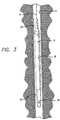
- the instrument probe generally includes three sections: a cable head 25 connected to the support cable, a camera head 26, and a light head 28, as is illustrated in greater detail in FIGS. 3, 4, and 5.
- the light head is attached to the camera head by three legs 30, two of which are shown.
- the distal end section 32 of the support cable is coupled to an optical transmitter or converter 34, where electrical signals representing images from the camera are converted into optical signals.
- optical transmitter or converter 34 Such electrical/optical converters and couplers for coupling the converter to the optical fiber are well known in the art.
- the optical signals are typically transmitted from the optical converter through an optical fiber 50 in the support cable 16 to the surface.
- the electricity carried by the cable can be converted in the electrical section 36 into the voltages required by the camera 38, the light head 28, and the electrical/optical converter 34.
- the voltage supplied by the cable may be 100 Vdc, while the camera operates on 12 Vdc, and the light head on 50 Vdc.
- Such converter boards are well known in the art, such as Model SWA175-4300 by Power-One, Inc., Camarillo, Calif.
- power is transmitted from the controller at the surface to the support cable via slip rings at the winch drum, in accordance with techniques known to those skilled in the art.
- the camera is a charge coupled device (CCD) type television camera that is capable of providing high speed, high resolution images in relatively dim light.
- CCD charge coupled device
- One suitable camera is the CCD Video Camera Module, model number XC 37 made by Sony Corporation.
- the camera system includes a lens 40, which can for example be a fisheye lens, and an outer protective or port window 42, which seals and protects the camera 38 from high temperature and high pressure fluids that can exist in a well.
- the light head 28 preferably includes a lamp, such as halogen lamp 46, a dome 47 covering the lamp 46, and electrical conductors 48 routed through the support legs 30 of the light head mounted to the camera head.
- a down-hole instrument cable in accordance with the invention includes an optical fiber 50 which is centrally located in the cable for carrying optical signals over long distances, and which is capable of operating at elevated temperatures.
- an optical fiber 50 which is centrally located in the cable for carrying optical signals over long distances, and which is capable of operating at elevated temperatures.
- multiple optical fibers may be used to provide a fiber optic cable.
- the optical fiber is preferably hermetically sealed in a layer of inorganic material 52, such as carbon, to protect the optical fiber from the deleterious effects of hydrogen and other gases, which can cause attenuation of the optical signal, particularly at elevated temperatures and pressures.
- the coating of inorganic material is typically a very thin layer less than 500 ⁇ applied to the optical fiber over the outer cladding layer of the optical fiber, and is preferably covered with a polymer coating 54, which can be a thermosetting acrylate coating resin such as 2-hydroxyethyl acrylate or hydroxypropyl acrylate.
- the optical fiber is a 50/125 CPC3 multi-mode optical fiber available from Corning.
- the diameter of the core of the optical fiber is about 0.050 mm (0.002 in); the outer diameter of the cladding is about 0.125 mm (0.005 in), and the outer diameter of the polymer coating is about 0.250 mm (0.10 in).
- the hermetically coated optical fiber is also preferably coated with a layer of silicone 56, which is in turn covered in a layer of tetrafluoroethylene (TFE) fluorocarbon polymer 58, to provide a surface coating with a low coefficient of friction.
- TFE tetrafluoroethylene
- the hermetically coated optical fiber, together with the coatings of silicone and TFE, are disposed in a protective sheath 60, which in one preferred embodiment is a stainless steel tube laser welded longitudinally, having a wall thickness of about 0.200 mm (0.008 in), so that it is thin enough to be relatively flexible.
- the protective sheath additionally provides a fluid seal.
- the stainless steel is preferably formed from a strip of stainless steel, which is folded in the shape of a tube. As the tube is folded, the coated optical fiber is inserted in the tube.
- the stainless steel protective sheath is advantageous because it can be laser welded, which results in less heat being applied to its contents during assembly.
- Olen tubes formed from copper or brass and soldered have been used in conventional techniques, but it has been found over the years that when a soldered copper or brass tube has an extended length, the solder joint tends to split open.
- An inert gel layer 62 is also preferably injected into the protective sheath around the coated optical fiber as the sheath is folded into the shape of a tube and laser welded. The inert gel layer functions to reduce shock, friction and abrasion that the optical fiber would otherwise experience due to the rolling and unrolling of the cable on the winch drum, and other twisting and bending motions which the cable undergoes during use.
- the inert gel also helps to support the weight of the optical fiber within the protective sheath, to prevent the optical fiber from rupturing itself due to its own weight when the support cable is suspended in a well bore.
- One inert gel typically used is a thixotropic buffer tube compound having a viscosity of about 280 ⁇ 15, (Penetrometer, ASTM D-217) and smooth, buttery consistency, and is available under the trade name "SYNCOFOX" from Synco Chemical Corporation.
- an inner insulator jacket 64 Surrounding the protective sheath is an inner insulator jacket 64, preferably made of a high temperature resistant material which is an electrical insulator, having a relatively high melting point exceeding 148 °C (298 °F), such as polypropylene which has a melting point at about 168-171 °C (333-340 °F).
- a high temperature resistant material which is an electrical insulator, having a relatively high melting point exceeding 148 °C (298 °F), such as polypropylene which has a melting point at about 168-171 °C (333-340 °F).
- Other materials which also may be suitable for use as an insulator jacket are high temperature resistant fluorocarbon polymers such as TFE, and ethylene-tetrafluoroethylene copolymer (ETFE), sold under the trade name "TEFZEL" by E. I. du Pont.
- the inner insulator jacket typically has a thickness of about 0.254 mm (0.010 in), and an outer diameter of
- an inner layer of electrically conductive strands 66 is a single layer of a braid of bare copper wire strands, which is braided onto the polypropylene inner insulator jacket 64 as the jacket is extruded over the stainless steel protective sheath 60.
- electrically conductive strands 66 which in one embodiment is a single layer of a braid of bare copper wire strands, which is braided onto the polypropylene inner insulator jacket 64 as the jacket is extruded over the stainless steel protective sheath 60.
- the inner insulator jacket 64 may not be included and the braid of copper 66 may be formed directly on the protective sheath 60.
- An outer insulator jacket 68 also preferably formed of a material having a relatively high melting point, and in this embodiment is also polypropylene, but which may also be formed of the other materials mentioned above in relation to the inner jacket 64, surrounds the inner layer of electrically conductive strands, and typically has a wall thickness of about 0.56 mm (0.022 in) and an outer diameter of about 3.30 mm (0.13 in).
- This layer is preferably formed in two extrusions. In the first extrusion, the polypropylene flows into the copper braid resulting in a stabilizing jacket. The second extrusion provides the thickness of the layer 68 required for fluid seal purposes.
- the outer jacket 68 also forms an electrical insulator between the strength members 70 which are used for conducting electricity and the copper braid layer 66.
- a plurality of strength member strands 70 preferably surround the outer insulator jacket 68, and in one preferred embodiment comprise an inner layer 71 of strength member strands wound helically around the outer insulator jacket in one direction, and an outer layer 72 of stainless steel armor strength member strands wound helically around the inner layer of strength member strands in an opposite serve or winding.
- the opposite serves of strength member strands help prevent the cable from becoming twisted.
- the strength member strands were formed of galvanized improved plow steel. Other embodiments may use stainless steel as the strands or an alloy known as MP 35 for particularly corrosive environments, such as where hydrogen sulfide is present.
- an exemplary total diameter of the cable 16 is approximately 5.72 mm (0.225 in), and with minor variations in the thickness of the various layers of the cable, the total diameter can typically range from about 4.76 mm (3/16 in) to about 7.94 mm (5/16 in).
- the plurality of strength member strands are electrically conductive, and can provide a leg of an electrical power supply loop.
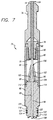
- the support cable 16 includes a cable termination assembly 74, as is illustrated in FIGS. 7, 8 and 9.
- the cable termination assembly generally includes an electrical conductive cable head body 76 coaxially disposed about the distal end of the support cable 16, an electrically conductive rope socket body 78 disposed within and secured to the cable head body 76 and coaxially disposed about the support cable, an electrically conductive clamp ring 80 disposed within the cable head body and secured over the rope socket body, and an electrically conductive contact sub-assembly 82 secured to a distal end of the cable head body.
- Down-hole well fluids typically can enter the cable head body through the proximal end of the lumen 84 extending axially through the cable head body over the outer armor strength member strands of the cable, particularly at high pressures, permitting well fluids to enter the interior chamber 86 of the cable head body.
- the rope socket body is typically secured to the cable head body by set screws 88 in cable head body.
- the plurality of strength member strands are terminated a short distance distally of the rope socket body, are folded back over the conical flange 90 of the rope socket body, and are matingly locked in place over the conical flange by the clamp ring 80, completing an electrical connection of the strength member strands to the cable head body.
- the number of the strength member strands folded back determine the break-away force required for the cable to be separated from the instrument probe. By judiciously selecting the number of the folded back strength member strands, the force may be set so that if the instrument probe becomes stuck in a well, the cable can be pulled free of the instrument probe, and the probe can be recovered separately. Strength members not folded back are cut off.
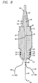
- the outer insulator jacket 68 is not terminated at this point, and the rest of the cable, including the outer insulator jacket, electrical conductors, inner insulator jacket, protective sheath and buffer layers, and the optical fiber of the cable continue on through the inner chamber 86 of the cable head body to extend through an axial lumen 94 of the contact subassembly 82.
- the sealing nipple 96 of the contact subassembly includes an exterior annular recessed portion 100, for snap-fit mating with a generally conical, flexible sealing boot 102, having an internal rib 104 corresponding to the recess 100 of the sealing nipple.
- the boot includes a narrow aperture 106, which fits tightly over the outer insulator jacket of the cable, and is further compressed over the cable and sealing nipple to form a seal between the contact subassembly and the well fluids by the high pressure of the well fluids.
- the cable exits through an aperture 108 of the contact sub-assembly at the distal end 110 of the contact subassembly.
- the contact subassembly is connected to the distal end of the cable head body by external proximal threads 112 which are matingly secured to corresponding internal threads 114 of the distal portion of the cable head body.
- the distal portion of the contact subassembly includes a shoulder 116 for receiving the chassis 118 of the converter assembly 34, and includes sockets 120 for set screws for securing the chassis of the converter assembly to the contact subassembly.
- O-ring seals 122 are provided in sockets 124 for further sealing of the distal end of the contact subassembly and the chassis of the converter assembly from well fluid pressure. As is shown in FIGS.
- an electrical connector 126 is electrically connected to the contact subassembly, completing the electrical connection through the contact subassembly and strength member strands, to provide a first electrical terminal for the camera head, light head, and electro/optical converter.
- the outer insulator jacket 68 typically terminates a short distance distally of the contact subassembly, exposing the inner layer of electrically conductive strands, to which an electrical connector 130 is electrically connected, such as by welding, soldering, bolts or screws, or the like, to provide a second electrical terminal.
- the distal end 134 of the optical fiber is located distally of the contact subassembly for connection to the electro/optical converter, for communicating signal data from the camera to the surface equipment.
- the sealing nipple can be sealed by an appropriate sealing material, which can for example comprise a first layer of adhesive backed TFE tape 136, typically about 12.7 mm (0.5 in) wide, a second layer of splicing tape 140, such as 23# rubber splicing tape available from 3M, and a third layer of all-weather tape 142 such as Super 88 all-weather vinyl tape available from 3M.
- the well fluid pressure has been found to compress the multiple tape layers to also effectively seal the contact assembly from the well fluids.
- the electrical and optical connections of the support cable to the instrument probe are made fluid tight for use in high pressure well fluid environments.
- the seal is made of standard components, the seal is economical to provide and manufacturing on a repeatable basis is facilitated.
- the layers of mechanical, thermal and electrical insulation in the cable surrounding the optical fiber minimize attenuation of signal data carried by the optical fiber which can occur due to damage by hydrogen and other gases at elevated temperatures and pressures, and severing or fractures of the optical fiber due to mechanical stresses.
- attenuation of the signal data communicated from the instrument probe is further minimized.
- the electrical conductors in the down-hole instrument cable of the invention which can be used for carrying electrical power from the surface for operation of the instrument probe or other devices can also be used to conduct electrical signals, especially when the instrument probe can be operated from battery power carried by the instrument probe itself.
- the size of the cable is minimized by the dual function of the strength member strands to protect the cable from physical damage and as part of an electrical path.
Claims (10)
- Bohrloch-Instrumentenkabel (16) mit reduziertem Durchmesser, gekennzeichnet durch:einen Lichtwellenleiter (50) mit einem Überzug auf dessen äußerer Oberfläche,eine schützende Pufferschicht, welche den genannten Lichtwellenleiter und den genannten Überzug auf der genannten äußeren Oberfläche des Lichtwellenleiters umgibt;eine Schutzhülle (60), welche den genannten Lichtwellenleiter und die genannte schützende Pufferschicht umgibt;einen ersten Isolator (64), der die genannte schützende Röhre umgibt, wobei der genannte erste Isolator aus einem wärmebeständigen Werkstoff mit verhältnismäßig hohem Schmelzpunkt gebildet wird;eine Schicht elektrischer Leiter (66), welche den genannten ersten Isolator umgibt;einen zweiten Isolator (68), der die genannte Schicht elektrischer Leiter umgibt, wobei der genannte zweite Isolator aus einem wärmebeständigen Werkstoff mit verhältnismäßig hohem Schmelzpunkt gebildet wird; undeine Mehrzahl elektrisch leitfähiger Widerstandselementstränge (70); welche den genannten zweiten Isolator umgeben und eine äußere Oberfläche des Kabels bilden.
- Kabel mit reduziertem Durchmesser nach Anspruch 1, ferner gekennzeichnet durch eine Schicht einer Gelsubstanz (62), die sich zwischen der genannten schützenden, metallischen Rühre (60) und der genannten Pufferschicht befindet.
- Kabel mit reduziertem Durchmesser nach einem der vorstehenden Ansprüche, ferner dadurch gekennzeichnet, dass die schützende Pufferschicht eine Silikonschicht (62) aufweist.
- Kabel mit reduziertem Durchmesser nach Anspruch 3, ferner dadurch gekennzeichnet, dass die genannte schützende Pufferschicht eine Schicht aus Tetrafluorethylen (58) aufweist, die sich über der genannten Silikonschicht (62) befindet.
- Kabel mit reduziertem Durchmesser nach einem der vorstehenden Ansprüche, ferner dadurch gekennzeichnet, dass die genannte Schutzhülle eine Edelstahlröhre umfasst.
- Kabel mit reduziertem Durchmesser nach einem der vorstehenden Ansprüche, ferner dadurch gekennzeichnet, dass der genannte Lichtwellenleiter einen einzelnen Lichtwellenleiter umfasst, der sich zentral in dem genannten Kabel befindet.
- Kabel mit reduziertem Durchmesser nach einem der vorstehenden Ansprüche, ferner gekennzeichnet durch eine elektrisch leitfähige Kontakt-Baugruppe (82) mit einem Dichtungselement (96), wobei das genannte Dichtungselement eine Öffnung (106) aufweist, die sich axial dort hindurch erstreckt, wobei sich der genannte ungepanzerte Abschnitt des genannten Kabels (16) durch die genannte Öffnung des genannten Dichtungselements erstreckt, und ferner mit einer Dichtungseinrichtung, die über der genannten Öffnung in dem genannten Dichtungselement und des genannten ungepanzerten Abschnitts des genannten Kabels angeordnet ist, so dass der proximale Abschnitt der genannten Kontakt-Baugruppe gegen Bohrlochfluids abgedichtet wird.
- Kabel mit reduziertem Durchmesser nach einem der Ansprüche 1 bis 6, ferner gekennzeichnet durch ein leitfähiges Kabelendverschlusskörper (76), der elektrisch mit der genannten Mehrzahl elektrisch leitfähiger Widerstandselementstränge verbunden ist, wobei die genannte Mehrzahl elektrisch leitfähiger Widerstandselementstränge in dem genannten leitfähigen Kabelendverschlusskörper endet; und
mit einer leitfähigen Kontakt-Baugruppe (82) mit proximalen und distalen Enden, wobei die genannte Kontakt-Baugruppe elektrisch mit dem genannten Kabelendverschlusskörper verbunden ist, wobei die genannte Kontakt-Baugruppe einen ersten elektrischen Anschluss zur Verbindung mit einem Bohrloch-Instrument vorsieht, wobei die genannte Kontakt-Baugruppe eine Öffnung (94) aufweist, die sich axial dort hindurch erstreckt, wobei ein verbleibender Abschnitt des genannten Kabels den genannten Lichtwellenleiter, die schützende Pufferschicht, die schützende Röhre, die ersten und zweiten Isolatoren und die Schicht elektrischer Leiter umfasst, die sich durch die genannte Öffnung in der genannten Kontakt-Baugruppe erstrecken, wobei die genannte Schicht elektrischer Leiter einen zweiten elektrischen Anschluss zur Verbindung mit dem genannten Bohrloch-Instrument vorsieht, und wobei der genannte Lichtwellenleiter einen optischen Anschluss für das genannte Bohrloch-Instrument vorsieht. - Kabel mit reduziertem Durchmesser nach Anspruch 8, ferner dadurch gekennzeichnet, dass die genannte Kontakt-Baugruppe (82) ein Dichtungselement (96) an dem proximalen Ende der Kontakt-Baugruppe aufweist, wobei die genannte Öffnung an dem proximalen Ende der genannten Kontakt-Baugruppe und der genannte verbleibende Abschnitt des genannten Kabels sich genannte Öffnung in dem genannten Dichtungselement um den genannten verbleibenden Abschnitt des genannten Kabels durch eine elastische Manschette (102) abgedichtet wird.
- Kabel mit reduziertem Durchmesser nach Anspruch 8, ferner dadurch gekennzeichnet, dass die genannte Kontakt-Baugruppe (82) ein Dichtungselement (96) an dem proximalen Ende der Kontakt-Baugruppe aufweist, wobei die genannte Öffnung an dem proximalen Ende der genannten Kontakt-Baugruppe und der genannte verbleibende Abschnitt des genannten Kabels sich durch das genannte Dichtungselement erstrecken, und wobei die genannte Öffnung in dem genannten Dichtungselement durch eine Mehrzahl von Schichten von Dichtungsband (136, 140, 142) um den genannten verbleibenden Abschnitt des genannten Kabels abgedichtet wird.
Applications Claiming Priority (3)
| Application Number | Priority Date | Filing Date | Title |
|---|---|---|---|
| US6639293A | 1993-05-21 | 1993-05-21 | |
| US66392 | 1993-05-21 | ||
| PCT/US1994/005664 WO1994028450A1 (en) | 1993-05-21 | 1994-05-20 | Reduced diameter down-hole instrument cable |
Publications (3)
| Publication Number | Publication Date |
|---|---|
| EP0656127A1 EP0656127A1 (de) | 1995-06-07 |
| EP0656127A4 EP0656127A4 (de) | 1996-06-19 |
| EP0656127B1 true EP0656127B1 (de) | 2001-10-04 |
Family
ID=22069237
Family Applications (1)
| Application Number | Title | Priority Date | Filing Date |
|---|---|---|---|
| EP94917451A Expired - Lifetime EP0656127B1 (de) | 1993-05-21 | 1994-05-20 | Bohrloch-instrumentenkabel mit reduzierten durchmesser |
Country Status (5)
| Country | Link |
|---|---|
| US (1) | US5493626A (de) |
| EP (1) | EP0656127B1 (de) |
| CA (1) | CA2140748C (de) |
| DE (1) | DE69428496T2 (de) |
| WO (1) | WO1994028450A1 (de) |
Families Citing this family (53)
| Publication number | Priority date | Publication date | Assignee | Title |
|---|---|---|---|---|
| US5495547A (en) * | 1995-04-12 | 1996-02-27 | Western Atlas International, Inc. | Combination fiber-optic/electrical conductor well logging cable |
| WO1996041066A1 (en) * | 1995-06-07 | 1996-12-19 | Dhv International, Inc. | Logging system combining video camera and sensors for environmental downhole conditions |
| US5892176A (en) * | 1996-11-05 | 1999-04-06 | Phillip E. Pruett | Smooth surfaced fiber optic logging cable for well bores |
| EP0938621B1 (de) * | 1996-11-14 | 2004-09-29 | Camco International Inc. | Kommunikationsrohr in einem bohrlochwerkzeug |
| US6195489B1 (en) * | 1997-01-31 | 2001-02-27 | Fujikura Ltd. | Optical fiber cord, ribbon cord using the same and ribbon cord branch line |
| CA2225153A1 (en) | 1997-02-07 | 1998-08-07 | James C. Hunziker | Combination fiber-optic/electrical conductor well logging cable |
| GB2368921B (en) * | 1997-09-10 | 2002-07-17 | Western Atlas Int Inc | Optical fibre wellbore logging cable |
| NO325106B1 (no) * | 1997-09-10 | 2008-02-04 | Western Atlas Int Inc | Anordning og fremgangsmate for a bestemme lengden av en kabel i en bronn ved bruk av optiske fibre |
| US6060662A (en) * | 1998-01-23 | 2000-05-09 | Western Atlas International, Inc. | Fiber optic well logging cable |
| US6229453B1 (en) | 1998-01-26 | 2001-05-08 | Halliburton Energy Services, Inc. | Method to transmit downhole video up standard wireline cable using digital data compression techniques |
| ID25807A (id) * | 1998-03-06 | 2000-11-09 | Shell Int Research | Peralatan pendeteksi aliran masuk dan sistem penggunaannya |
| EP1688585A3 (de) * | 1998-12-17 | 2009-11-04 | Chevron USA, Inc. | Apparat und Verfahren zum Schutz von Vorrichtungen, insbesondere faseroptische Vorrichtungen in aggressiven Umgebungen |
| AU782553B2 (en) * | 2000-01-05 | 2005-08-11 | Baker Hughes Incorporated | Method of providing hydraulic/fiber conduits adjacent bottom hole assemblies for multi-step completions |
| EP1241746A1 (de) * | 2001-03-14 | 2002-09-18 | Europäische Organisation für astronomische Forschung in der südlichen Hemisphäre | Schmalbandige Hochleistungsfaserlaser |
| US7049506B2 (en) * | 2001-06-20 | 2006-05-23 | Philip Head | Conductor system |
| WO2003021301A2 (en) | 2001-08-29 | 2003-03-13 | Sensor Highway Limited | Method and apparatus for determining the temperature of subterranean wells using fiber optic cable |
| US20030169179A1 (en) * | 2002-03-11 | 2003-09-11 | James Jewell D. | Downhole data transmisssion line |
| US20030215197A1 (en) * | 2002-05-14 | 2003-11-20 | Simon Jonathan N. | Combined optical and electrical transmission line |
| WO2004066000A2 (en) * | 2003-01-15 | 2004-08-05 | Sabeus Photonics, Inc. | System and method for deploying an optical fiber in a well |
| CN100439650C (zh) * | 2003-06-12 | 2008-12-03 | 上海光导传输技术研究所 | 深井探测光纤传输系统 |
| US7777643B2 (en) * | 2004-05-06 | 2010-08-17 | Halliburton Energy Services, Inc. | Optical communications with a bottom hole assembly |
| US20050247450A1 (en) * | 2004-05-10 | 2005-11-10 | Schlumberger Technology Corporation | Flame and Heat Resistant Oilfield Tools |
| WO2006059158A1 (en) * | 2004-12-01 | 2006-06-08 | Philip Head | Cables |
| US7920765B2 (en) * | 2005-06-09 | 2011-04-05 | Schlumberger Technology Corporation | Ruggedized optical fibers for wellbore electrical cables |
| DE102005032619B4 (de) * | 2005-07-13 | 2015-07-30 | Abdul Amir Shubbar | Hochtemperaturbeständige Kabelummantelung |
| US8295665B2 (en) | 2006-08-30 | 2012-10-23 | Afl Telecommunications Llc | Downhole cables with both fiber and copper elements |
| GB2443224A (en) * | 2006-10-26 | 2008-04-30 | Remote Marine Systems Ltd | Connector having removable conductor |
| CN201160014Y (zh) * | 2007-12-13 | 2008-12-03 | 上海波汇通信科技有限公司 | 复合光纤的高压电力电缆 |
| US9593573B2 (en) * | 2008-12-22 | 2017-03-14 | Schlumberger Technology Corporation | Fiber optic slickline and tools |
| US8903243B2 (en) | 2009-09-17 | 2014-12-02 | Schlumberger Technology Corporation | Oilfield optical data transmission assembly joint |
| CH701871A1 (de) * | 2009-09-25 | 2011-03-31 | Brugg Ag Kabelwerke | Elektrooptisches Kabel. |
| WO2011094257A1 (en) * | 2010-01-27 | 2011-08-04 | Afl Telecommunications Llc | Logging cable |
| GB201003846D0 (en) * | 2010-03-09 | 2010-04-21 | Viking Intervention Technology | Cablehead |
| US9650843B2 (en) | 2011-05-31 | 2017-05-16 | Schlumberger Technology Corporation | Junction box to secure and electronically connect downhole tools |
| CA2851877C (en) * | 2011-10-17 | 2021-02-09 | Schlumberger Canada Limited | Dual use cable with fiber optic packaging for use in wellbore operations |
| BR112014010635B1 (pt) | 2011-11-03 | 2020-12-29 | Fastcap Systems Corporation | sistema de registro em log |
| US8929701B2 (en) | 2012-02-15 | 2015-01-06 | Draka Comteq, B.V. | Loose-tube optical-fiber cable |
| WO2014004026A1 (en) | 2012-06-28 | 2014-01-03 | Schlumberger Canada Limited | High power opto-electrical cable with multiple power and telemetry paths |
| JP5920923B2 (ja) | 2012-09-03 | 2016-05-18 | 矢崎総業株式会社 | ワイヤハーネス |
| US9091154B2 (en) | 2013-03-28 | 2015-07-28 | Schlumberger Technology Corporation | Systems and methods for hybrid cable telemetry |
| WO2014176447A1 (en) | 2013-04-24 | 2014-10-30 | Wireco Worldgroup Inc. | High-power low-resistance electromechanical cable |
| EA038707B1 (ru) | 2013-12-20 | 2021-10-07 | Фасткэп Системз Корпорейшн | Устройство электромагнитной телеметрии |
| NO343149B1 (no) | 2014-04-22 | 2018-11-19 | Vision Io As | Fremgangsmåte for visuell inspeksjon og logging |
| WO2016122446A1 (en) | 2015-01-26 | 2016-08-04 | Schlumberger Canada Limited | Electrically conductive fiber optic slickline for coiled tubing operations |
| US9915798B2 (en) * | 2015-12-28 | 2018-03-13 | Prysmian S.P.A. | Downhole cable with reduced diameter |
| US10049789B2 (en) | 2016-06-09 | 2018-08-14 | Schlumberger Technology Corporation | Compression and stretch resistant components and cables for oilfield applications |
| US10971284B2 (en) * | 2017-06-27 | 2021-04-06 | Halliburton Energy Services, Inc. | Power and communications cable for coiled tubing operations |
| WO2019121590A1 (en) * | 2017-12-20 | 2019-06-27 | Nkt Hv Cables Ab | Submarine power cable comprising a fibre optic cable |
| US11125936B2 (en) * | 2019-02-26 | 2021-09-21 | The Government Of The United States Of America, As Represented By The Secretary Of The Navy | Thermal insulator for fiber optic components |
| JP7280067B2 (ja) * | 2019-03-11 | 2023-05-23 | 矢崎総業株式会社 | 光ファイバケーブルの端末処理構造、及び、これを用いた光モジュール、光コネクタ |
| CN111485830A (zh) * | 2020-05-12 | 2020-08-04 | 信达科创(唐山)石油设备有限公司 | 一种带有识别标记的封装管缆及其制备方法 |
| CN112764179B (zh) * | 2020-12-31 | 2022-08-16 | 中油奥博(成都)科技有限公司 | 一种下井光缆及下井方法 |
| PL442554A1 (pl) | 2022-10-18 | 2024-04-22 | Czado Mariusz Czadowo | Kabel zasilająco-telekomunikacyjny |
Family Cites Families (9)
| Publication number | Priority date | Publication date | Assignee | Title |
|---|---|---|---|---|
| JPS5499646A (en) * | 1977-12-16 | 1979-08-06 | Post Office | Submarine communication cable |
| US4579420A (en) * | 1983-06-16 | 1986-04-01 | Olin Corporation | Two-pole powered ruggedized optical fiber cable and method and apparatus for forming the same |
| GB8316494D0 (en) * | 1983-06-17 | 1983-07-20 | Bicc Plc | Flexible elongate body |
| JPS622412A (ja) * | 1985-06-28 | 1987-01-08 | 株式会社フジクラ | 光ファイバ複合架空線 |
| US4952012A (en) * | 1988-11-17 | 1990-08-28 | Stamnitz Timothy C | Electro-opto-mechanical cable for fiber optic transmission systems |
| US5202944A (en) * | 1990-06-15 | 1993-04-13 | Westech Geophysical, Inc. | Communication and power cable |
| US5140319A (en) * | 1990-06-15 | 1992-08-18 | Westech Geophysical, Inc. | Video logging system having remote power source |
| US5150443A (en) * | 1990-08-14 | 1992-09-22 | Schlumberger Techonolgy Corporation | Cable for data transmission and method for manufacturing the same |
| US5275038A (en) * | 1991-05-20 | 1994-01-04 | Otis Engineering Corporation | Downhole reeled tubing inspection system with fiberoptic cable |
-
1994
- 1994-05-20 WO PCT/US1994/005664 patent/WO1994028450A1/en active IP Right Grant
- 1994-05-20 DE DE69428496T patent/DE69428496T2/de not_active Expired - Fee Related
- 1994-05-20 CA CA002140748A patent/CA2140748C/en not_active Expired - Lifetime
- 1994-05-20 EP EP94917451A patent/EP0656127B1/de not_active Expired - Lifetime
- 1994-12-30 US US08/368,389 patent/US5493626A/en not_active Expired - Lifetime
Also Published As
| Publication number | Publication date |
|---|---|
| EP0656127A1 (de) | 1995-06-07 |
| DE69428496D1 (de) | 2001-11-08 |
| WO1994028450A1 (en) | 1994-12-08 |
| EP0656127A4 (de) | 1996-06-19 |
| DE69428496T2 (de) | 2002-05-23 |
| US5493626A (en) | 1996-02-20 |
| CA2140748C (en) | 1999-08-10 |
| CA2140748A1 (en) | 1994-12-08 |
Similar Documents
| Publication | Publication Date | Title |
|---|---|---|
| EP0656127B1 (de) | Bohrloch-instrumentenkabel mit reduzierten durchmesser | |
| EP0533771B1 (de) | Bohrloch-video-messkabel | |
| US5202944A (en) | Communication and power cable | |
| WO1996041066A1 (en) | Logging system combining video camera and sensors for environmental downhole conditions | |
| US5485745A (en) | Modular downhole inspection system for coiled tubing | |
| US5275038A (en) | Downhole reeled tubing inspection system with fiberoptic cable | |
| US5419188A (en) | Reeled tubing support for downhole equipment module | |
| CA2172652C (en) | Combination fiber-optic/electrical conductor well logging cable | |
| US7699114B2 (en) | Electro-optic cablehead and methods for oilwell applications | |
| US5939679A (en) | Video push-cable | |
| US7381900B2 (en) | Power cable for direct electric heating system | |
| US20020044750A1 (en) | Undersea telecommunications cable | |
| GB2275953A (en) | Downhole logging tool | |
| JPS6217704A (ja) | 光フアイバ遠隔通信のための海底ライン | |
| US4585287A (en) | Cable connector for use in downhole drilling and logging operations | |
| IE49416B1 (en) | Improvements in or relating to connectors for sealed containers | |
| US4259543A (en) | Cable termination | |
| CN109031568B (zh) | 用于海缆连接的分支器 | |
| GB2424315A (en) | Ocean bottom seismic sensor cable system including torque-relieving swivel | |
| JPS61209410A (ja) | 光フアイバ通信海底ケーブル | |
| CA1257118A (en) | Joint for optical fiber submarine cables | |
| AU2022347096A1 (en) | Cable monitoring apparatus and method | |
| GB2321973A (en) | Well logging cable with optic fibre in metal tube with conductive liner | |
| CA2244833A1 (en) | Combination fiber optic/electrical well logging cable | |
| NO318116B1 (no) | Nedhulls instrumentkabel med redusert diameter |
Legal Events
| Date | Code | Title | Description |
|---|---|---|---|
| PUAI | Public reference made under article 153(3) epc to a published international application that has entered the european phase |
Free format text: ORIGINAL CODE: 0009012 |
|
| AK | Designated contracting states |
Kind code of ref document: A1 Designated state(s): DE FR GB NL |
|
| 17P | Request for examination filed |
Effective date: 19950601 |
|
| A4 | Supplementary search report drawn up and despatched |
Effective date: 19960502 |
|
| AK | Designated contracting states |
Kind code of ref document: A4 Designated state(s): DE FR GB NL |
|
| RAP1 | Party data changed (applicant data changed or rights of an application transferred) |
Owner name: DHV INTERNATIONAL, INC. |
|
| 17Q | First examination report despatched |
Effective date: 19990303 |
|
| GRAG | Despatch of communication of intention to grant |
Free format text: ORIGINAL CODE: EPIDOS AGRA |
|
| GRAG | Despatch of communication of intention to grant |
Free format text: ORIGINAL CODE: EPIDOS AGRA |
|
| GRAH | Despatch of communication of intention to grant a patent |
Free format text: ORIGINAL CODE: EPIDOS IGRA |
|
| GRAH | Despatch of communication of intention to grant a patent |
Free format text: ORIGINAL CODE: EPIDOS IGRA |
|
| GRAA | (expected) grant |
Free format text: ORIGINAL CODE: 0009210 |
|
| AK | Designated contracting states |
Kind code of ref document: B1 Designated state(s): DE FR GB NL |
|
| REF | Corresponds to: |
Ref document number: 69428496 Country of ref document: DE Date of ref document: 20011108 |
|
| REG | Reference to a national code |
Ref country code: GB Ref legal event code: IF02 |
|
| ET | Fr: translation filed | ||
| PGFP | Annual fee paid to national office [announced via postgrant information from national office to epo] |
Ref country code: DE Payment date: 20020422 Year of fee payment: 9 |
|
| PLBE | No opposition filed within time limit |
Free format text: ORIGINAL CODE: 0009261 |
|
| STAA | Information on the status of an ep patent application or granted ep patent |
Free format text: STATUS: NO OPPOSITION FILED WITHIN TIME LIMIT |
|
| 26N | No opposition filed | ||
| PG25 | Lapsed in a contracting state [announced via postgrant information from national office to epo] |
Ref country code: DE Free format text: LAPSE BECAUSE OF NON-PAYMENT OF DUE FEES Effective date: 20031202 |
|
| PGFP | Annual fee paid to national office [announced via postgrant information from national office to epo] |
Ref country code: GB Payment date: 20130528 Year of fee payment: 20 |
|
| PGFP | Annual fee paid to national office [announced via postgrant information from national office to epo] |
Ref country code: NL Payment date: 20130526 Year of fee payment: 20 Ref country code: FR Payment date: 20130606 Year of fee payment: 20 |
|
| REG | Reference to a national code |
Ref country code: NL Ref legal event code: V4 Effective date: 20140520 |
|
| REG | Reference to a national code |
Ref country code: GB Ref legal event code: PE20 Expiry date: 20140519 |
|
| PG25 | Lapsed in a contracting state [announced via postgrant information from national office to epo] |
Ref country code: GB Free format text: LAPSE BECAUSE OF EXPIRATION OF PROTECTION Effective date: 20140519 |