EP0655877A2 - Einrichtung zum Schutz des Transformators eines Mikrowellenherdes gegen Überhitzung - Google Patents
Einrichtung zum Schutz des Transformators eines Mikrowellenherdes gegen Überhitzung Download PDFInfo
- Publication number
- EP0655877A2 EP0655877A2 EP94118200A EP94118200A EP0655877A2 EP 0655877 A2 EP0655877 A2 EP 0655877A2 EP 94118200 A EP94118200 A EP 94118200A EP 94118200 A EP94118200 A EP 94118200A EP 0655877 A2 EP0655877 A2 EP 0655877A2
- Authority
- EP
- European Patent Office
- Prior art keywords
- high voltage
- coil
- voltage transformer
- microwave oven
- overheated
- Prior art date
- Legal status (The legal status is an assumption and is not a legal conclusion. Google has not performed a legal analysis and makes no representation as to the accuracy of the status listed.)
- Granted
Links
- 238000010438 heat treatment Methods 0.000 claims description 8
- 238000009413 insulation Methods 0.000 claims description 5
- 239000005011 phenolic resin Substances 0.000 claims description 3
- 230000002787 reinforcement Effects 0.000 claims description 3
- 239000012774 insulation material Substances 0.000 claims 1
- 238000010586 diagram Methods 0.000 description 4
- 238000010276 construction Methods 0.000 description 2
- 239000000463 material Substances 0.000 description 2
- 230000005684 electric field Effects 0.000 description 1
- 238000012423 maintenance Methods 0.000 description 1
- 238000004519 manufacturing process Methods 0.000 description 1
- 238000005259 measurement Methods 0.000 description 1
- 238000000034 method Methods 0.000 description 1
- -1 polybutylene Polymers 0.000 description 1
- 229920001748 polybutylene Polymers 0.000 description 1
- 238000004804 winding Methods 0.000 description 1
Images


Classifications
-
- H—ELECTRICITY
- H05—ELECTRIC TECHNIQUES NOT OTHERWISE PROVIDED FOR
- H05B—ELECTRIC HEATING; ELECTRIC LIGHT SOURCES NOT OTHERWISE PROVIDED FOR; CIRCUIT ARRANGEMENTS FOR ELECTRIC LIGHT SOURCES, IN GENERAL
- H05B6/00—Heating by electric, magnetic or electromagnetic fields
- H05B6/64—Heating using microwaves
- H05B6/66—Circuits
- H05B6/666—Safety circuits
-
- H—ELECTRICITY
- H01—ELECTRIC ELEMENTS
- H01F—MAGNETS; INDUCTANCES; TRANSFORMERS; SELECTION OF MATERIALS FOR THEIR MAGNETIC PROPERTIES
- H01F27/00—Details of transformers or inductances, in general
- H01F27/40—Structural association with built-in electric component, e.g. fuse
- H01F27/402—Association of measuring or protective means
-
- H—ELECTRICITY
- H05—ELECTRIC TECHNIQUES NOT OTHERWISE PROVIDED FOR
- H05B—ELECTRIC HEATING; ELECTRIC LIGHT SOURCES NOT OTHERWISE PROVIDED FOR; CIRCUIT ARRANGEMENTS FOR ELECTRIC LIGHT SOURCES, IN GENERAL
- H05B6/00—Heating by electric, magnetic or electromagnetic fields
- H05B6/64—Heating using microwaves
- H05B6/66—Circuits
- H05B6/662—Aspects related to the boost transformer of the microwave heating apparatus
-
- H—ELECTRICITY
- H01—ELECTRIC ELEMENTS
- H01F—MAGNETS; INDUCTANCES; TRANSFORMERS; SELECTION OF MATERIALS FOR THEIR MAGNETIC PROPERTIES
- H01F27/00—Details of transformers or inductances, in general
- H01F27/40—Structural association with built-in electric component, e.g. fuse
- H01F27/402—Association of measuring or protective means
- H01F2027/406—Temperature sensor or protection
Definitions
- the present invention relates to a device for preventing a high voltage transformer of a microwave oven from being overheated, which directly senses a temperature in a second coil of the high voltage transformer of the microwave oven and thereby supplies or cuts off power to the transformer according to the temperature.
- a microwave oven is a cooker for heating food by a high frequency electric field, which includes a heating chamber and a machine chamber.
- a magnetron and a high voltage transformer are disposed in the machine chamber.
- the high voltage transformer applies a high voltage to the magnetron to make the magnetron generate ultra microwaves, and the magnetron irradiates the ultra microwaves into the heating chamber so as to activate molecular movements in the food put in the heating chamber, so that the food is heated.
- the high voltage transformer has a large quantity of coils which generate a large quantity of heat when the transformer is operated. Accordingly, the operation efficiency of the microwave oven is lowered and components of the microwave oven can be damaged when the machine chamber is overheated due to the heat generated from the coils. Further, there is a possibility of danger that the microwave oven will catch a fire.
- FIG. 5 is a circuit diagram of a conventional device for preventing the temperature in the machine chamber of a microwave oven from being over-elevated as described above.
- a high voltage transformer T1 has a first coil L1 to which an alternating current voltage is applied, and a second coil L2 at which a circuit including a high voltage fuse F1, a high voltage condenser C1, a high voltage diode D1, and a magnetron M1 is constructed.
- high voltage fuse F1 is cut off or high voltage diode D1 is shorted before high voltage fuse F1 is cut off, when an overcurrent flows through the second circuit L2.
- high voltage diode D1 is shorted before high voltage fuse F1 is cut off, a closed loop comprising second coil L2, high voltage fuse F1, high voltage condenser C1, and high voltage diode D1 is constructed. At this moment, a large quantity of currents abruptly flows in this closed loop, and thereby high voltage fuse F1 is cut off.
- the temperature of the high voltage transformer is not directly sensed but indirectly preestimated through the electric currents flowing therethrough, and accordingly there is a disadvantage that the temperature of the high voltage transformer is not prevented precisely and efficiently from being over-elevated and there is a possiblity of danger that the electric current can be cut off by a current over-inflowing through the fuse, even when the high voltage transformer is not overheated.
- the conventional device whenever the high voltage diode is shorted and/or the high voltage fuse is cut off, these damaged components, which are very expensive, must be replaced with new ones to operate the transformer again, and thereby the maintenance expense is relatively very high.
- the present invention has been made to overcome the above described disadvantages of the conventional device, and accordingly it is an object of the present invention to provide a device for preventing a high voltage transformer of a microwave oven from being overheated, which directly senses a temperature in a second coil of the high voltage transformer of the microwave oven and regulates power supply to a second coil of the transformer according to the temperature so as to prevent the temperature of the high voltage transformer from being over-elevated precisely and efficiently and to ensure a stable operation of the transformer, and which can be manufactured and maintained at a low expense.
- the present invention provides a device for preventing a high voltage transformer of a microwave oven from being overheated comprising: a high voltage transformer having a first coil to which an alternating current is supplied, and a second coil to which a voltage higher than that of the first coil is applied; a generator circuit for generating an ultra microwave by the voltage applied thereto from the second coil, and for radiating the ultra microwave into a heating chamber of the microwave oven; and a thermostat connected to one of two terminals of the first coil and disposed on the outer surface of the second coil.
- the generator circuit includes a magnetron electrically connected to the second coil to radiate an ultra microwave into a heating chamber of the microwave oven, a condenser disposed between the magnetron and the second to be connected in series to them, and a high voltage diode connected in parallel to the magnetron.
- the thermostat is inserted in a bracket for the electric insulation thereof from second coil
- the bracket is made of a material having a high insulation property such as polybuthylene terephtalate or Phenol resin and attached on an outer surface of second coil
- the bracket includes a main body having a recess formed at the central part thereof, a base plate supporting the main body and having a rear surface which is curved in such a manner to be suitably attached on an outer surface of the high voltage transformer, a crossing bar crossing over the recess with urging down the thermostat in the recess, and a bolt or a screw inserted through one end of the crossing bar to be engaged in the screw hole.
- the bracket includes a main body having a recess formed at the central part thereof, a base plate supporting the main body and having a rear surface which is curved in such a manner to be suitably attached on an outer surface of the high voltage transformer, and two elastic hooks disposed in the recess, each of the hooks having a protuberance formed at an upper free end thereof, and a reinforcement girder provided at a rear surface thereof.
- a device for preventing a high voltage transformer of a microwave oven from being overheated In a device for preventing a high voltage transformer of a microwave oven from being overheated according to the present invention, two contact points of the thermostat are maintained to be connected with each other so as to guarantee a stable power supply to the first coil and thereby normal operations of the high voltage transformer and the magnetron.
- the two contact points are separated from each other and the power supply to the first coil is interrupted, and accordingly the normal operations of the high voltage transformer and the magnetron are stopped.
- the two contact points are restored to be connected with each other, and thereby the electric power is supplied to the first coil again.
- FIG. 1 is a circuit diagram of a device for preventing a high voltage transformer of a microwave oven from being overheated according to one embodiment of the present invention.
- a high voltage transformer T2 has a first coil L3 to which an alternating current voltage is applied, and a second coil L4 at which a circuit including a high voltage condenser C2, a high voltage diode D2, and a magnetron M2 is constructed. Magnetron M2 is connected in parallel to high voltage diode D2.
- a thermostat TH is connected to one of two terminals t1, t2 of first coil L3 of high voltage transformer T2 to which an alternating current of low voltage is supplied therethrough.
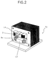
- Thermostat TH is directly disposed on the outer surface of second coil L4 of high voltage transformer T2 to sense the temperature of high voltage transformer T2 as shown in FIG. 2 because a component generating the largest quantity of heat in high voltage transformer T2 is second coil L4 the number of the windings of which is relatively large, and thermostat TH regulates power supply to first coil L3 according to the temperature.
- thermostat TH is installed on second coil L4 with being inserted in a bracket 3 for the electric insulation thereof from second coil L4.
- Bracket 3 comprises a material having a high insulation property such as polybutylene terephtalate (PBT) or a phenol resin and attached on the outer surface of second coil L4.
- PBT polybutylene terephtalate
- phenol resin a material having a high insulation property
- FIGs. 3A and 3B are plan and sectional views of a bracket 3 according to one embodiment of the present invention.
- bracket 3 has a main body 5 and a base plate 6.
- Main body 5 has a recess 4 formed at the central part thereof and a screw hole 7 formed at an inner corner thereof.
- the rear surface of base plate 6 is curved in such a manner to be attached to the outer surface of high voltage transformer T2 suitably.
- thermostat TH is inserted in recess 4, and is urged down therein by a crossing bar 8 crossing over recess 4, and then fixed therein by an element such as a screw 8a or a bolt inserted through a corner of crossing bar 8 to be engaged in screw hole 7.
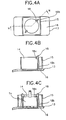
- FIGs. 4A and 4B are plan and sectional views of a bracket 13 according to another embodiment of the present invention.
- Bracket 13 of the present embodiment is similar to bracket 3 shown in FIGs. 3A and 3B except that bracket 13 has two hooks 18 disposed in a recess 14 instead of screw hole 7 and crossing bar 8. That is, bracket 13 has a main body 15 and a base plate 16.
- Main body 15 has a recess 14 formed at the central part thereof and the rear surface of base plate 16 is curved in such a manner to be attached to the outer surface of high voltage transformer T2 suitably.
- In recess 14 are disposed two elastic hooks 18, each of which has a protuberance 18a formed at the upper free end thereof and a reinforcement girder 18b provided at the back thereof.
- thermostat TH is inserted between two elastic hooks 18 in recess 14, and fixed therein by two elastic hooks 18.
- two contact points P1 and P2 of thermostat TH are maintained to be connected with each other so as to guarantee a stable power supply to first coil L3 and thereby normal operations of high voltage transformer T2 and magnetron M2, when high voltage transformer T2 is below a predetermined temperature.
- the temperature of the transformer is not estimated through an indirect method such as a measurement of the quantity of an electric current flowing through the second coil but sensed directly by the thermostat responding the temperature. Accordingly, the high voltage transformer is prevented from being overheated in a stable and reliable manner.
- the power supply circuit of the magnetron is automatically switched to be opened or closed according to the temperature, troubles of replacing damaged components such as a high voltage fuse with new ones whenever the circuit is opened can be avoided and the expense for maintaining the transformer can be reduced.
- a device for preventing a high voltage transformer of a microwave oven from being overheated because the thermostat is connected to the first coil of the high voltage transformer, components for low voltage, which are much cheaper than components of high voltage, can be adopted for the thermostat, terminals of the thermostat, and other components. Accordingly, the manufacturing cost of the device can be reduced compared with the conventional device in which a high voltage fuse is connected to the second coil.
Landscapes
- Engineering & Computer Science (AREA)
- Power Engineering (AREA)
- Physics & Mathematics (AREA)
- Electromagnetism (AREA)
- Control Of High-Frequency Heating Circuits (AREA)
- Regulation Of General Use Transformers (AREA)
- Protection Of Transformers (AREA)
Applications Claiming Priority (4)
| Application Number | Priority Date | Filing Date | Title |
|---|---|---|---|
| KR9324739 | 1993-11-19 | ||
| KR930024724 | 1993-11-19 | ||
| KR9324724 | 1993-11-19 | ||
| KR930024739 | 1993-11-19 |
Publications (3)
| Publication Number | Publication Date |
|---|---|
| EP0655877A2 true EP0655877A2 (de) | 1995-05-31 |
| EP0655877A3 EP0655877A3 (de) | 1995-10-18 |
| EP0655877B1 EP0655877B1 (de) | 1998-04-29 |
Family
ID=26629997
Family Applications (1)
| Application Number | Title | Priority Date | Filing Date |
|---|---|---|---|
| EP94118200A Expired - Lifetime EP0655877B1 (de) | 1993-11-19 | 1994-11-18 | Einrichtung zum Schutz des Transformators eines Mikrowellenherdes gegen Überhitzung |
Country Status (4)
| Country | Link |
|---|---|
| US (1) | US5625520A (de) |
| EP (1) | EP0655877B1 (de) |
| JP (1) | JPH07245871A (de) |
| DE (1) | DE69409924T2 (de) |
Cited By (5)
| Publication number | Priority date | Publication date | Assignee | Title |
|---|---|---|---|---|
| EP0867906A1 (de) * | 1997-02-26 | 1998-09-30 | Samsung Electronics Co., Ltd. | Mikrowellenofen |
| EP0884929A3 (de) * | 1997-06-14 | 1999-06-09 | Samsung Electronics Co., Ltd. | Hochspannungsversorgung und Sicherung |
| WO2004027792A1 (en) * | 2002-09-17 | 2004-04-01 | Matsushita Electric Industrial Co., Ltd. | Transformer and transformer unit having the same |
| EP1427261A1 (de) * | 2002-12-05 | 2004-06-09 | Samsung Electronics Co., Ltd. | Mikrowellenofen |
| EP2568768A3 (de) * | 2011-09-07 | 2013-03-27 | Samsung Electronics Co., Ltd. | Mikrowelle |
Families Citing this family (4)
| Publication number | Priority date | Publication date | Assignee | Title |
|---|---|---|---|---|
| KR19990002105A (ko) * | 1997-06-19 | 1999-01-15 | 배순훈 | 기계식 전자렌지의 돌입전류 방지회로 |
| KR100358580B1 (ko) * | 1999-07-28 | 2002-10-25 | 삼성전자 주식회사 | 전자렌지용 고압트랜스 및 그 제조방법 |
| KR20030093678A (ko) * | 2002-06-05 | 2003-12-11 | 삼성전자주식회사 | 출력 레벨을 조절하는 전자렌지의 안전장치 |
| KR20040003176A (ko) | 2002-07-02 | 2004-01-13 | 삼성전자주식회사 | 전자렌지 및 그 고압부제어회로 |
Family Cites Families (8)
| Publication number | Priority date | Publication date | Assignee | Title |
|---|---|---|---|---|
| BE793158A (fr) * | 1972-03-30 | 1973-04-16 | Amana Refrigeration Inc | Dispositif de protection de circuit electrique |
| JPS5240338U (de) * | 1975-09-17 | 1977-03-22 | ||
| SE404108B (sv) * | 1977-02-10 | 1978-09-18 | Philips Svenska Ab | Anordning for overvakning av temperaturen hos en elektrisk komponent |
| US4454554A (en) * | 1980-07-28 | 1984-06-12 | The General Industries Company | Coil bobbin |
| FR2615318A1 (fr) * | 1987-05-11 | 1988-11-18 | Optelec Applic Optiq Electro R | Transformateur electrique pour four a micro-ondes |
| DE3741381A1 (de) * | 1987-12-07 | 1990-03-01 | Bosch Siemens Hausgeraete | Schaltungsanordnung zur mikrowellen-leistungssteuerung bei magnetrons |
| AT397318B (de) * | 1989-09-29 | 1994-03-25 | Zumtobel Ag | Stützteil für wicklungsköpfe für elektrische drahtwicklungen |
| FR2656191B1 (fr) * | 1989-12-15 | 1996-06-07 | Thomson Electromenager Sa | Procede de commande d'un four a micro-ondes et four a micro-ondes mettant en óoeuvre ce procede. |
-
1994
- 1994-11-15 US US08/341,861 patent/US5625520A/en not_active Expired - Lifetime
- 1994-11-18 EP EP94118200A patent/EP0655877B1/de not_active Expired - Lifetime
- 1994-11-18 DE DE69409924T patent/DE69409924T2/de not_active Expired - Lifetime
- 1994-11-21 JP JP6286460A patent/JPH07245871A/ja active Pending
Non-Patent Citations (11)
| Title |
|---|
| "Bimetal Detectors Current Sensitive Thermal Winding Protection", MICROTHERM, 4 April 1990 (1990-04-04) |
| "INTERNATIONAL STANDARD", vol. 3, 1991, pages: 85 |
| "Thermal Protection of Windings", MICROTHERM, 1 December 1990 (1990-12-01) |
| BRITISH STANDARD, BS415, 1979 |
| DRAWING PRODUCED BY DE LOGHI SPA 15 MAY 1990 |
| DRAWINGS PRODUCED BY TABUCHI ELECTRIC 1990 |
| ELECTROLUX TRANSFORMER LEC 240VL 27-01-1989 |
| EXPLANITORY NOTES OF THE ELECTRICAL AND THERMAL CONNECTION OF THE ELECTROLUX TRANSFORMERS TYPES 3961015 TO 3961018 |
| INVOICES DATED 1990 |
| LETTER OF ELECTROLUX |
| RYTON DISIGN GUIDE 1988 |
Cited By (8)
| Publication number | Priority date | Publication date | Assignee | Title |
|---|---|---|---|---|
| EP0867906A1 (de) * | 1997-02-26 | 1998-09-30 | Samsung Electronics Co., Ltd. | Mikrowellenofen |
| EP0884929A3 (de) * | 1997-06-14 | 1999-06-09 | Samsung Electronics Co., Ltd. | Hochspannungsversorgung und Sicherung |
| WO2004027792A1 (en) * | 2002-09-17 | 2004-04-01 | Matsushita Electric Industrial Co., Ltd. | Transformer and transformer unit having the same |
| US6970065B2 (en) | 2002-09-17 | 2005-11-29 | Matsushita Electric Industrial Co., Ltd. | Transformer and transformer unit having the same |
| EP1427261A1 (de) * | 2002-12-05 | 2004-06-09 | Samsung Electronics Co., Ltd. | Mikrowellenofen |
| CN1313772C (zh) * | 2002-12-05 | 2007-05-02 | 三星电子株式会社 | 微波炉和温度灵敏开关及微波炉用变压器组件 |
| US7365294B2 (en) | 2002-12-05 | 2008-04-29 | Samsung Electronics Co., Ltd. | Microwave oven |
| EP2568768A3 (de) * | 2011-09-07 | 2013-03-27 | Samsung Electronics Co., Ltd. | Mikrowelle |
Also Published As
| Publication number | Publication date |
|---|---|
| EP0655877A3 (de) | 1995-10-18 |
| DE69409924T2 (de) | 1999-01-21 |
| DE69409924D1 (de) | 1998-06-04 |
| US5625520A (en) | 1997-04-29 |
| EP0655877B1 (de) | 1998-04-29 |
| JPH07245871A (ja) | 1995-09-19 |
Similar Documents
| Publication | Publication Date | Title |
|---|---|---|
| EP0477633B1 (de) | Hochfrequenz-Heizapparat mit einem Wechselrichter als Stromversorgungseinheit | |
| EP0655877B1 (de) | Einrichtung zum Schutz des Transformators eines Mikrowellenherdes gegen Überhitzung | |
| EP0301805A1 (de) | Hochfrequenzheizgerät | |
| KR910001986B1 (ko) | 마그네트론 급전장치 | |
| JPH0482191A (ja) | 高周波加熱装置 | |
| US7365294B2 (en) | Microwave oven | |
| EP0449275B1 (de) | Mikrowellenofen mit einer Leistungsversorgung ausgestattet mit einem steuerbaren Wechselrichter | |
| EP1239706B1 (de) | Stromversorgungssystem für Mikrowellenofen | |
| JP3800808B2 (ja) | 誘導加熱インバータ装置 | |
| JP2974864B2 (ja) | マグネトロン駆動用変圧器 | |
| JP3458736B2 (ja) | マグネトロン駆動用電源 | |
| JP3174844B2 (ja) | 高周波加熱装置 | |
| KR100286179B1 (ko) | 전자레인지 | |
| JPH05326130A (ja) | 電磁調理器 | |
| KR0135241B1 (ko) | 고압트랜스의 온도과승 방지장치 | |
| CN102997297B (zh) | 微波炉 | |
| KR0139296Y1 (ko) | 전자 렌지의 고압 트랜스 보호용 퓨즈 장착 구조 | |
| JP3583816B2 (ja) | 電子レンジの安全回路 | |
| EP0540246B1 (de) | Stromversorgungseinheit eines Mikrowellenherdes | |
| KR200301584Y1 (ko) | 인버터방식 전자렌지의 트랜스 | |
| KR950010597Y1 (ko) | 전자렌지용 고압트랜스의 온도상승 방지구조 | |
| JPH0236233Y2 (de) | ||
| JPS6154175A (ja) | ヒ−タ断線検出回路 | |
| KR200143524Y1 (ko) | 전자 렌지의 고압 트랜스 보호용 퓨즈 장착 구조 | |
| KR100476407B1 (ko) | 전기보온밥솥의 과열방지회로 |
Legal Events
| Date | Code | Title | Description |
|---|---|---|---|
| PUAI | Public reference made under article 153(3) epc to a published international application that has entered the european phase |
Free format text: ORIGINAL CODE: 0009012 |
|
| AK | Designated contracting states |
Kind code of ref document: A2 Designated state(s): DE FR GB |
|
| PUAL | Search report despatched |
Free format text: ORIGINAL CODE: 0009013 |
|
| AK | Designated contracting states |
Kind code of ref document: A3 Designated state(s): DE FR GB |
|
| 17P | Request for examination filed |
Effective date: 19960410 |
|
| GRAG | Despatch of communication of intention to grant |
Free format text: ORIGINAL CODE: EPIDOS AGRA |
|
| 17Q | First examination report despatched |
Effective date: 19970808 |
|
| GRAG | Despatch of communication of intention to grant |
Free format text: ORIGINAL CODE: EPIDOS AGRA |
|
| GRAH | Despatch of communication of intention to grant a patent |
Free format text: ORIGINAL CODE: EPIDOS IGRA |
|
| TPAD | Observations filed by third parties |
Free format text: ORIGINAL CODE: EPIDOS TIPA |
|
| GRAH | Despatch of communication of intention to grant a patent |
Free format text: ORIGINAL CODE: EPIDOS IGRA |
|
| GRAA | (expected) grant |
Free format text: ORIGINAL CODE: 0009210 |
|
| AK | Designated contracting states |
Kind code of ref document: B1 Designated state(s): DE FR GB |
|
| REF | Corresponds to: |
Ref document number: 69409924 Country of ref document: DE Date of ref document: 19980604 |
|
| ET | Fr: translation filed | ||
| PLBE | No opposition filed within time limit |
Free format text: ORIGINAL CODE: 0009261 |
|
| STAA | Information on the status of an ep patent application or granted ep patent |
Free format text: STATUS: NO OPPOSITION FILED WITHIN TIME LIMIT |
|
| 26N | No opposition filed | ||
| REG | Reference to a national code |
Ref country code: GB Ref legal event code: IF02 |
|
| REG | Reference to a national code |
Ref country code: GB Ref legal event code: 732E |
|
| REG | Reference to a national code |
Ref country code: FR Ref legal event code: TP |
|
| PGFP | Annual fee paid to national office [announced via postgrant information from national office to epo] |
Ref country code: DE Payment date: 20091112 Year of fee payment: 16 |
|
| PGFP | Annual fee paid to national office [announced via postgrant information from national office to epo] |
Ref country code: GB Payment date: 20091118 Year of fee payment: 16 Ref country code: FR Payment date: 20091123 Year of fee payment: 16 |
|
| GBPC | Gb: european patent ceased through non-payment of renewal fee |
Effective date: 20101118 |
|
| REG | Reference to a national code |
Ref country code: DE Ref legal event code: R119 Ref document number: 69409924 Country of ref document: DE Effective date: 20110601 Ref country code: DE Ref legal event code: R119 Ref document number: 69409924 Country of ref document: DE Effective date: 20110531 |
|
| REG | Reference to a national code |
Ref country code: FR Ref legal event code: ST Effective date: 20110801 |
|
| PG25 | Lapsed in a contracting state [announced via postgrant information from national office to epo] |
Ref country code: DE Free format text: LAPSE BECAUSE OF NON-PAYMENT OF DUE FEES Effective date: 20110531 |
|
| PG25 | Lapsed in a contracting state [announced via postgrant information from national office to epo] |
Ref country code: FR Free format text: LAPSE BECAUSE OF NON-PAYMENT OF DUE FEES Effective date: 20101130 |
|
| PG25 | Lapsed in a contracting state [announced via postgrant information from national office to epo] |
Ref country code: GB Free format text: LAPSE BECAUSE OF NON-PAYMENT OF DUE FEES Effective date: 20101118 |