EP0654857B1 - Elektrischen Steckanschluss mit ausklappbarer Verschlussblende - Google Patents
Elektrischen Steckanschluss mit ausklappbarer Verschlussblende Download PDFInfo
- Publication number
- EP0654857B1 EP0654857B1 EP19940410102 EP94410102A EP0654857B1 EP 0654857 B1 EP0654857 B1 EP 0654857B1 EP 19940410102 EP19940410102 EP 19940410102 EP 94410102 A EP94410102 A EP 94410102A EP 0654857 B1 EP0654857 B1 EP 0654857B1
- Authority
- EP
- European Patent Office
- Prior art keywords
- front plate
- shutter
- blanking plate
- openings
- cylindrical element
- Prior art date
- Legal status (The legal status is an assumption and is not a legal conclusion. Google has not performed a legal analysis and makes no representation as to the accuracy of the status listed.)
- Expired - Lifetime
Links
Images


Classifications
-
- H—ELECTRICITY
- H01—ELECTRIC ELEMENTS
- H01R—ELECTRICALLY-CONDUCTIVE CONNECTIONS; STRUCTURAL ASSOCIATIONS OF A PLURALITY OF MUTUALLY-INSULATED ELECTRICAL CONNECTING ELEMENTS; COUPLING DEVICES; CURRENT COLLECTORS
- H01R13/00—Details of coupling devices of the kinds covered by groups H01R12/70 or H01R24/00 - H01R33/00
- H01R13/44—Means for preventing access to live contacts
- H01R13/447—Shutter or cover plate
- H01R13/453—Shutter or cover plate opened by engagement of counterpart
- H01R13/4532—Rotating shutter
Definitions
- the present invention relates to a socket outlet comprising a support element for current distribution cells, a front plate arranged to receive a plug of electrical equipment, a cylindrical element disposed between said support element and said front plate and supporting a retractable shutter designed to occupy a position rest in which it closes openings made in the front plate and provided to give access to said current distribution cells, and a position withdrawn in which it releases said openings.
- Document GB-A-2209888 describes a base equipped with a shutter mechanism requiring a large stroke for unlocking the shutter, which is provided with ramps for its rotation.
- the presence of such a stroke combined with the use of a spring compression requires a large size incompatible with the dimensions fixed by standards.
- the present invention proposes to provide a socket outlet which guarantees a efficient sealing of the passage openings to the contact cells and which has in addition to additional security due to the fact that said closure is maintained if all the pins are not introduced simultaneously into the corresponding openings.
- the presence of the guide ramps on the cylindrical element cooperating with the opening the shutter circle provides a compact base.
- the first section of the guidance substantially parallel to the axis of the cylindrical element allows the studs to be released shutter partially engaged in the openings of the front plate.
- the second inclined section relative to this axis causes a rotation of the shutter about said axis. This combined shutter guidance takes place on the same ramp.
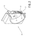
- the socket-outlet current 10 shown mainly consists of an element 11 for supporting the current distribution cells 12, of a cassette 13 for mounting a shutter 14, a return spring 15 of the leaf type, which is arranged to ensure an axial stress on the shutter, and a front plate 16, mounted at the front of the socket outlet 10.
- the element 11 for supporting the cells 12 is a molded plastic part, by example of circular section comprising, in the embodiment shown, two circular openings 17 opening into the current distribution cells 12, and a earth plug 18 of cylindrical shape arranged perpendicularly on the front face of said element 11.
- Cassette 13 is also a molded plastic part having a bottom circular 19 surrounded by a rim substantially perpendicular to this bottom.
- the diameter of the circular bottom is approximately equal to the diameter of the element 11 for supporting the alveoli.
- This bottom has three circular openings 20 respectively intended for passage of the two current distribution pins 33 of a plug 32 and of the earth 18.
- the circular bottom 19 carries a cylindrical element 21 provided with at least one and preferably two guide ramps 22 having a helical or inclined section relative to to the axis of said stud.
- ramps which can be in the form of beads protruding or under that of hollow grooves, are arranged to cooperate with the shutter 14 to transform an axial thrust on the latter into a combined movement of axial translation and rotation about the axis of the cylindrical element 21.
- the number of ramps is advantageously two, but this number could be reduced to one or increased three or four.
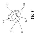
- the cassette 13 and cylindrical element 21 assembly is an exemplary embodiment which can be advantageously replaced by a cylindrical element 21 alone, as shown in figure 4, provided with its support shoulder 34 of the spring 15 and of any fixing means to the front plate 16.
- the return spring 15 has two elastic arms 23 and an interior opening 24 which authorizes its installation on the cylindrical element 21.
- the two elastic arms 23 are raised relative to the central part which comprises the interior opening, so as to rest at two points by their ends on the shutter 14.
- the shutter 14 has a substantially annular central portion 25 and two arms 26 which each have at their end a stud 27 corresponding in position and dimension to current distribution cells 12 and to the openings 17 of the element 11.
- the part central 25 has a circular opening 28 and two notches 29 diametrically opposite.
- the circular opening 28 makes it possible to adapt the shutter to the cylindrical element 21.
- the two notches 29 are arranged to cooperate with the partially helical ramps 22 which have the shape of protruding beads. It is obvious that if the ramps appear under the form of hollow grooves, the notches 29 are replaced by two lugs which penetrate in said grooves and guide them during movement of the shutter.
- the front plate 16 has the shape of a quadrangular box provided with an annular rim 30 arranged on its front face which has three circular openings 31 corresponding in position at the three circular openings 20 at the bottom of the cassette 13.
- the shutter 14 At rest, the shutter 14 is in positive support against the faceplate 16.
- the studs 27, which have a flat or convex front surface, are engaged in the openings circular 31 due to an axial stress exerted by the leaf spring 15.
- the axial stress exerted by the pins of the plug on the studs 27 of the shutter causes displacement helical shutter, i.e. a combination of translational movement axial and rotating around the axis. This movement makes it possible to retract the shutter and clear the openings giving access to the current distribution cells.
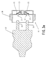
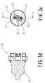
- Figure 3A shows the file 32 in the approach phase of the front faceplate 16.
- the shutter 14 is in place and the circular openings 31 are closed by the studs 27.
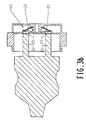
- FIG. 3B shows the plug 32 in a position in which the ends of its pins 33 are in contact with the studs 27.
- the arms 23 of the spring 15 are in abutment against the shutter 14 and exert a stress which keeps the studs in the openings of the front plate.
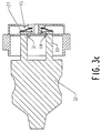
- Figure 3C shows sheet 32 in an intermediate position in which the thrust exerted by the pins 33 is greater to the force exerted by the spring 15 on the shutter 14.
- the studs 27 begin to clear openings on the faceplate.
- Figure 3D shows sheet 32 fully engaged in socket 10. The studs are retracted. The position of the shutter 14, and more particularly of its pads 27, is shown in Figure 3E.
- this set constitutes a kind of rocker which prevents the introduction of a single rod towards a single cell if a push identical to that exerted by this rod on one of the studs 27 is not exerted simultaneously on the other stud.
- the tilting caused in the case of the introduction of a single rod makes the other stud penetrate into the corresponding opening 31 of the faceplate and blocks the shutter in the rest position, thus preventing access to the cells. Therefore, the spring blade constitutes a safety device preventing any access to the cells by means of a anything other than the pins of an electrical outlet plug.
- FIG. 4 represents a perspective view of the cylindrical element 21 and in particular guide rails 22.
- the rails have a first section 22a parallel to the axis of the base and a second section 22b inclined by relation to this axis.
- the first section clears the studs 27 from the openings 31 during of the introduction of the pins of a plug and the second section generates the movement of rotation necessary to laterally move these studs from the path followed by these pins.
- FIG. 5 shows another embodiment of a socket outlet, which differs from that described above in that it is designed for a three-prong plug.
- This base 10a is composed as above of an element 11a for supporting the cells of current distribution 12a, of a cassette 13a for mounting a shutter 14a, of a spring 15a and a 16a faceplate.
- the support 11a is provided with three circular openings 17a and an earth plug 18a.
- the cassette is provided with four circular openings 20a.
- the shutter is equipped with three arms 26a which each carry a stud 27a corresponding to a opening 31a of the front plate 16a.
- the return spring 15a has three arms 23a which bear on the three arms 26a of the shutter 14a.
- the base is intended either for a keyed socket, one of the three openings being reserved for a polarization card, the other two for the distribution of current, or to a three-phase outlet.
- an O-ring 40 is interposed between the front plate 16 or 16a and the shutter 14 or 14a to ensure a tight closure of the openings 31, by means of the studs 27 of the shutter 14 or 14a, taking advantage of the force spring support 15 or 15a.
Landscapes
- Connector Housings Or Holding Contact Members (AREA)
Claims (6)
- Steckdoseneinsatz mit einem Tragkörper für Stromverteilungskanäle, einer Frontplatte zur Aufnahme eines, zu einer elektrischen Ausrüstung gehörenden Steckers, einem zwischen dem genannten Tragkörper und der genannten Frontplatte angeordneten zylindrischen Element, auf dem ein versenkbares Verschlußelement montiert ist, das dazu dient, eine Ruhestellung, in der es in der Frontplatte ausgebildete Öffnungen für den Zugang zu den genannten Stromverteilungskanälen abdeckt, sowie eine Rückzugstellung einzunehmen, in der es die genannten Öffnungen freigibt, wobeider Einsatz (10, 10a) eine separate Feder (15, 15a) umfaßt, die auf dem genannten zylindrischen Element (21, 21a) gelagert ist, um das Verschlußelement (14, 14a) gegen die Rückseite der Frontplatte (16, 16a) zu drücken, wobei die Feder (15, 15a) als in Form einer Wippe wirkende Blattfeder ausgebildet ist,am genannten zylindrischen Element eine Führungsrampe (22) ausgebildet ist, um mit einer kreisrunden Öffnung (28) des Verschlußelements zusammenzuwirken, wobei die genannte Rampe einen, annähernd parallel zur Achse des zylindrischen Elements (21) verlaufenden, ersten Abschnitt (22a) sowie einen, in bezug auf die genannte Achse geneigten, zweiten Abschnitt (22b) aufweist, um eine kombinierte, in Axialrichtung verlaufende Translations- und eine, um die Achse des genannten zylindrischen Elements verlaufende Drehbewegung des Verschlußelements zu bewirken.
- Einsatz nach Anspruch 1, dadurch gekennzeichnet, daß die Führungsrampe (22) teilweise ein annähernd schraubenförmiges Profil aufweist.
- Einsatz nach Anspruch 1, dadurch gekennzeichnet, daß die Blattfeder (15, 15a) einen ringförmigen Mittelabschnitt und mindestens zwei, aus der Ebene dieses ringförmigen Teils hervorstehende Schenkel (23, 23a) aufweist, um in der Ruhestellung eine Druckkraft auf das Verschlußelement (14, 14a) auszuüben.
- Einsatz nach Anspruch 1, dadurch gekennzeichnet, daß das Verschlußelement (14, 14a) mindestens zwei Flügel (26, 26a) mit an den Enden dieser Flügel ausgebildeten Ansätzen (27, 27a) aufweist, wobei diese Ansätze dazu dienen, zumindest teilweise in die genannten Öffnungen (31, 31a) der Frontplatte einzugreifen.
- Einsatz nach Anspruch 4, dadurch gekennzeichnet, daß die genannten Ansätze (27, 27a) eine ebene oder konvexe Oberfläche aufweisen.
- Einsatz nach Anspruch 4, dadurch gekennzeichnet, daß er eine zwischen die Frontplatte (16, 16a) und das Verschlußelement (14, 14a) eingesetzte Dichtung (40) umfaßt.
Applications Claiming Priority (2)
| Application Number | Priority Date | Filing Date | Title |
|---|---|---|---|
| FR9314274A FR2713022B1 (fr) | 1993-11-24 | 1993-11-24 | Socle de prise de courant avec obturateur escamotable. |
| FR9314274 | 1993-11-24 |
Publications (2)
| Publication Number | Publication Date |
|---|---|
| EP0654857A1 EP0654857A1 (de) | 1995-05-24 |
| EP0654857B1 true EP0654857B1 (de) | 1998-02-04 |
Family
ID=9453341
Family Applications (1)
| Application Number | Title | Priority Date | Filing Date |
|---|---|---|---|
| EP19940410102 Expired - Lifetime EP0654857B1 (de) | 1993-11-24 | 1994-11-18 | Elektrischen Steckanschluss mit ausklappbarer Verschlussblende |
Country Status (4)
| Country | Link |
|---|---|
| EP (1) | EP0654857B1 (de) |
| DE (1) | DE69408411D1 (de) |
| ES (1) | ES2115182T3 (de) |
| FR (1) | FR2713022B1 (de) |
Families Citing this family (2)
| Publication number | Priority date | Publication date | Assignee | Title |
|---|---|---|---|---|
| GB2531963B (en) | 2011-09-09 | 2016-12-21 | Ifpl Group Ltd | Electrical socket |
| EP3352308B1 (de) * | 2017-01-23 | 2020-11-04 | Berker GmbH & Co. KG | Vordere abdeckungsvorrichtung für steckdose und steckdose mit einem solchen vorderabdeckungsgerät ausgestattet |
Family Cites Families (3)
| Publication number | Priority date | Publication date | Assignee | Title |
|---|---|---|---|---|
| GB628692A (en) * | 1947-09-10 | 1949-09-02 | Dorman & Smith Ltd | Improvements in and relating to a shutter device for electric socket apparatus |
| FR2271680A1 (en) * | 1974-05-14 | 1975-12-12 | Couqueberg Michel | Plug and socket with safety shutter - has guide slot in plug earth pin rotating shutter to align pin access holes |
| GB8721769D0 (en) * | 1987-09-16 | 1987-10-21 | Conblock Electrical Ltd | Electrical socket |
-
1993
- 1993-11-24 FR FR9314274A patent/FR2713022B1/fr not_active Expired - Fee Related
-
1994
- 1994-11-18 DE DE69408411T patent/DE69408411D1/de not_active Expired - Lifetime
- 1994-11-18 ES ES94410102T patent/ES2115182T3/es not_active Expired - Lifetime
- 1994-11-18 EP EP19940410102 patent/EP0654857B1/de not_active Expired - Lifetime
Also Published As
| Publication number | Publication date |
|---|---|
| FR2713022A1 (fr) | 1995-06-02 |
| EP0654857A1 (de) | 1995-05-24 |
| DE69408411D1 (de) | 1998-03-12 |
| FR2713022B1 (fr) | 1995-12-22 |
| ES2115182T3 (es) | 1998-06-16 |
Similar Documents
| Publication | Publication Date | Title |
|---|---|---|
| EP0528735B1 (de) | Selektive Vorrichtung für elektrische Verbindung, welche mit einer Sicherheitsscheibe und einer komplementären Scheibe ausgerüstet ist | |
| FR2463526A1 (fr) | Connecteur de cable a armure metallique sous gaine | |
| FR2707433A1 (fr) | Connecteur pour carte, en particulier pour carte électronique. | |
| FR2497609A1 (fr) | Dispositif de connexion du type a pousser-tirer | |
| EP0505256B1 (de) | Zweiteiliger Adapter für den Anschluss eines elektrischen Gerätes mit Stecker an eine Wandsteckdose | |
| EP0580505A1 (de) | Anpassungssystem zwischen einem Antennenstecker und der Buchse eines Funktelefons | |
| FR2975231A1 (fr) | Ensemble de connexion etanche | |
| EP0112258B1 (de) | Elektrische Sicherheitssteckdose insbesondere für explosive Atmosphäre | |
| FR2934091A1 (fr) | Prise de courant a fond de puits mobile et obturateur escamotable | |
| EP0580469B1 (de) | Steckverbindersatz und Befestigungsfläche insbesondere für die Avionik | |
| EP1318569B1 (de) | Elektrischer Steckanschluss mit Verschlussbuchsenblenden und Baureihe mit einem solchen Steckanschluss | |
| EP0763875A1 (de) | Elektrische Steckdose mit Verschlüsselungssystem | |
| EP0654857B1 (de) | Elektrischen Steckanschluss mit ausklappbarer Verschlussblende | |
| FR2518322A2 (fr) | Dispositif de connexion du type a " pousser-tirer " | |
| FR2967829A1 (fr) | Prise electrique comportant des montants lateraux mobiles en translation | |
| FR2584873A1 (fr) | Systeme de raccordement electrique pour un reseau specifique de distribution de courant, et adaptateur pour fiche de raccordement electrique et socle de prise de courant correspondants | |
| EP0685911B1 (de) | Koaxiales elektrisches Verbinderelement mit Schalt-Funktion und elektrischer Verbinder mit einem derartigen Verbinderelement | |
| EP0401097B1 (de) | Vorrichtung zum Verriegeln einer Verbindung | |
| EP0654858B1 (de) | Elektrischen Steckanschluss mit Verschlüsselungssystem | |
| FR2924535A1 (fr) | Appareillage electrique encastre a connexion rapide | |
| FR2684241A1 (fr) | Dispositif de connexion de securite pour branchement electrique. | |
| WO2023198438A1 (fr) | Prise électrique comprenant un piston mobile | |
| EP0576345A1 (de) | Elektrischer Steckverbinder mit Anschlusselementverrieglung | |
| EP4207506A1 (de) | Bausatz für einen elektrischen verbinder und elektrischer verbinder | |
| EP1672746B1 (de) | Steckdose ausgerüstet mit zusätzlichem Sicherungsmittel |
Legal Events
| Date | Code | Title | Description |
|---|---|---|---|
| PUAI | Public reference made under article 153(3) epc to a published international application that has entered the european phase |
Free format text: ORIGINAL CODE: 0009012 |
|
| AK | Designated contracting states |
Kind code of ref document: A1 Designated state(s): BE CH DE ES GB IT LI SE |
|
| 17P | Request for examination filed |
Effective date: 19951110 |
|
| 17Q | First examination report despatched |
Effective date: 19960410 |
|
| GRAG | Despatch of communication of intention to grant |
Free format text: ORIGINAL CODE: EPIDOS AGRA |
|
| GRAG | Despatch of communication of intention to grant |
Free format text: ORIGINAL CODE: EPIDOS AGRA |
|
| GRAH | Despatch of communication of intention to grant a patent |
Free format text: ORIGINAL CODE: EPIDOS IGRA |
|
| GRAH | Despatch of communication of intention to grant a patent |
Free format text: ORIGINAL CODE: EPIDOS IGRA |
|
| GRAA | (expected) grant |
Free format text: ORIGINAL CODE: 0009210 |
|
| AK | Designated contracting states |
Kind code of ref document: B1 Designated state(s): BE CH DE ES GB IT LI SE |
|
| PG25 | Lapsed in a contracting state [announced via postgrant information from national office to epo] |
Ref country code: IT Free format text: LAPSE BECAUSE OF FAILURE TO SUBMIT A TRANSLATION OF THE DESCRIPTION OR TO PAY THE FEE WITHIN THE PRESCRIBED TIME-LIMIT;WARNING: LAPSES OF ITALIAN PATENTS WITH EFFECTIVE DATE BEFORE 2007 MAY HAVE OCCURRED AT ANY TIME BEFORE 2007. THE CORRECT EFFECTIVE DATE MAY BE DIFFERENT FROM THE ONE RECORDED. Effective date: 19980204 Ref country code: GB Free format text: LAPSE BECAUSE OF FAILURE TO SUBMIT A TRANSLATION OF THE DESCRIPTION OR TO PAY THE FEE WITHIN THE PRESCRIBED TIME-LIMIT Effective date: 19980204 |
|
| REG | Reference to a national code |
Ref country code: CH Ref legal event code: EP |
|
| REF | Corresponds to: |
Ref document number: 69408411 Country of ref document: DE Date of ref document: 19980312 |
|
| PG25 | Lapsed in a contracting state [announced via postgrant information from national office to epo] |
Ref country code: SE Free format text: LAPSE BECAUSE OF FAILURE TO SUBMIT A TRANSLATION OF THE DESCRIPTION OR TO PAY THE FEE WITHIN THE PRESCRIBED TIME-LIMIT Effective date: 19980504 |
|
| PG25 | Lapsed in a contracting state [announced via postgrant information from national office to epo] |
Ref country code: DE Free format text: LAPSE BECAUSE OF FAILURE TO SUBMIT A TRANSLATION OF THE DESCRIPTION OR TO PAY THE FEE WITHIN THE PRESCRIBED TIME-LIMIT Effective date: 19980505 |
|
| REG | Reference to a national code |
Ref country code: ES Ref legal event code: FG2A Ref document number: 2115182 Country of ref document: ES Kind code of ref document: T3 |
|
| GBV | Gb: ep patent (uk) treated as always having been void in accordance with gb section 77(7)/1977 [no translation filed] |
Effective date: 19980204 |
|
| PG25 | Lapsed in a contracting state [announced via postgrant information from national office to epo] |
Ref country code: BE Free format text: LAPSE BECAUSE OF NON-PAYMENT OF DUE FEES Effective date: 19981130 |
|
| PGFP | Annual fee paid to national office [announced via postgrant information from national office to epo] |
Ref country code: CH Payment date: 19981210 Year of fee payment: 5 |
|
| PLBE | No opposition filed within time limit |
Free format text: ORIGINAL CODE: 0009261 |
|
| STAA | Information on the status of an ep patent application or granted ep patent |
Free format text: STATUS: NO OPPOSITION FILED WITHIN TIME LIMIT |
|
| 26N | No opposition filed | ||
| BERE | Be: lapsed |
Owner name: S.A. SCHNEIDER ELECTRIC Effective date: 19981130 |
|
| PG25 | Lapsed in a contracting state [announced via postgrant information from national office to epo] |
Ref country code: LI Free format text: LAPSE BECAUSE OF NON-PAYMENT OF DUE FEES Effective date: 19991130 Ref country code: CH Free format text: LAPSE BECAUSE OF NON-PAYMENT OF DUE FEES Effective date: 19991130 |
|
| PGFP | Annual fee paid to national office [announced via postgrant information from national office to epo] |
Ref country code: ES Payment date: 19991130 Year of fee payment: 6 |
|
| REG | Reference to a national code |
Ref country code: CH Ref legal event code: PL |
|
| PG25 | Lapsed in a contracting state [announced via postgrant information from national office to epo] |
Ref country code: ES Free format text: LAPSE BECAUSE OF NON-PAYMENT OF DUE FEES Effective date: 20001119 |
|
| REG | Reference to a national code |
Ref country code: ES Ref legal event code: FD2A Effective date: 20011214 |