EP0654673A1 - Méthode et dispositif pour la surveillance de l'isolation dans des réseaux continus et alternatifs non mis à la terre - Google Patents
Méthode et dispositif pour la surveillance de l'isolation dans des réseaux continus et alternatifs non mis à la terre Download PDFInfo
- Publication number
- EP0654673A1 EP0654673A1 EP94118162A EP94118162A EP0654673A1 EP 0654673 A1 EP0654673 A1 EP 0654673A1 EP 94118162 A EP94118162 A EP 94118162A EP 94118162 A EP94118162 A EP 94118162A EP 0654673 A1 EP0654673 A1 EP 0654673A1
- Authority
- EP
- European Patent Office
- Prior art keywords
- measurement
- value
- network
- voltage
- measuring
- Prior art date
- Legal status (The legal status is an assumption and is not a legal conclusion. Google has not performed a legal analysis and makes no representation as to the accuracy of the status listed.)
- Granted
Links
Images

Classifications
-
- G—PHYSICS
- G01—MEASURING; TESTING
- G01R—MEASURING ELECTRIC VARIABLES; MEASURING MAGNETIC VARIABLES
- G01R27/00—Arrangements for measuring resistance, reactance, impedance, or electric characteristics derived therefrom
- G01R27/02—Measuring real or complex resistance, reactance, impedance, or other two-pole characteristics derived therefrom, e.g. time constant
- G01R27/16—Measuring impedance of element or network through which a current is passing from another source, e.g. cable, power line
- G01R27/18—Measuring resistance to earth, i.e. line to ground
-
- G—PHYSICS
- G01—MEASURING; TESTING
- G01R—MEASURING ELECTRIC VARIABLES; MEASURING MAGNETIC VARIABLES
- G01R27/00—Arrangements for measuring resistance, reactance, impedance, or electric characteristics derived therefrom
- G01R27/02—Measuring real or complex resistance, reactance, impedance, or other two-pole characteristics derived therefrom, e.g. time constant
- G01R27/025—Measuring very high resistances, e.g. isolation resistances, i.e. megohm-meters
-
- G—PHYSICS
- G01—MEASURING; TESTING
- G01R—MEASURING ELECTRIC VARIABLES; MEASURING MAGNETIC VARIABLES
- G01R31/00—Arrangements for testing electric properties; Arrangements for locating electric faults; Arrangements for electrical testing characterised by what is being tested not provided for elsewhere
- G01R31/50—Testing of electric apparatus, lines, cables or components for short-circuits, continuity, leakage current or incorrect line connections
- G01R31/52—Testing for short-circuits, leakage current or ground faults
Definitions
- the invention relates to a method for monitoring the insulation of unearthed direct and alternating current networks according to the preamble of claim 1 and a device suitable for carrying out this method according to the preamble of claim 21.
- the invention is concerned with the insulation monitoring of unearthed direct current networks and alternating current networks in operation and in particular also of those alternating current networks in which leakage direct currents and low and high-frequency components occur due to connected direct current, alternating current or other power converters which occur via the unavoidable ohmic part of the Insulation resistance between the mains and earth flow.
- the ohmic part of the insulation resistance of the network can be measured during operation by superimposing a constant DC measurement voltage on the network via an ohmic network connection between the network and earth.
- the due this DC measuring voltage via the network coupling, the network and the ohmic insulation resistance, the measurement DC current flowing is proportional in size to the size of the ohmic insulation resistance, so that this resistance can be determined from the DC measurement current or a measurement current measurement value derived therefrom, such as a voltage.
- Interfering frequency influences can be filtered out by a low-pass filter.
- a direct current interference component based on a leakage direct current is added (or subtracted) to the measurement direct current, which leads to incorrect measurements when using a measurement direct voltage.
- an alternating pulse voltage with different pulse voltage values can be superimposed on the network instead of a DC measurement voltage.
- the respective measured current measured value is always only recorded after the network has settled to the respective pulse voltage value. The ohmic insulation resistance is then determined from the difference between two successive measured current measured values. The influence of the interference component is eliminated by forming the difference.
- the present invention is therefore based on the object of designing a method for monitoring the insulation of ungrounded direct and alternating current networks according to the preamble of claim 1 and a device suitable for carrying out this method according to the preamble of claim 21 so that it is easy to handle and with Simple measures to achieve shorter measuring times with any unearthed networks while avoiding measurement falsifications.
- a method for monitoring the insulation of unearthed direct and alternating current networks of the type mentioned in the preamble of claim 1 is distinguished according to the invention by the features listed in the characterizing part of this claim.
- the individual pulses of the pulse alternating voltage are thus always adapted in terms of their length to the respective existing network so that the next pulse voltage value is immediately switched over when the continuously monitored transient process has ended.
- This results in a constant adaptation of the measuring method to the current network conditions, so that optimally short measuring times can be achieved without any risk of incorrect measurements.
- the measurement result of the ohmic insulation resistance can be achieved using the new method after a measurement time which, depending on the size of the ohmic and capacitive parts of the insulation resistance, is only about 10% in the optimal case.
- the time intervals of the measuring times or the lengths of the mean value measuring intervals should become larger over time when monitoring each transient process. This is to prevent the monitoring process from being terminated prematurely because differences in the measurement samples which are too small and no longer readily measurable occur.
- By increasing the time intervals or measuring intervals it is achieved that there are always sufficiently large measurement sample differences during the transient process and thus the end of the transient process can be reliably detected.
- a starting value that is as small as possible should initially be selected, which, in the most unfavorable grid conditions, that is to say with a large time constant, just enables the measuring process to be reliably determined.
- the starting values of the measurement sample time interval or the mean value measurement interval can be selected in accordance with the regulations of claims 6 to 8, taking into account the respective network conditions.
- the enlargement of the measurement samples - time intervals or the average measurement intervals, which takes place during the monitoring of each transient process, should preferably be carried out in accordance with the regulations of claims 9 to 11 in order to simplify the method and to achieve perfect measurement results. According to claims 10 and 11 it can be achieved that the monitoring process does not end at a maximum measuring resolution of approximately 1% before the approx. 6-fold time constant of the transient process is reached, that is to say it is not terminated too early.
- claim 12 increases the measurement reliability and switches off incorrect measurements, for example those due to changing network conditions.
- very favorable conditions for averaging can be achieved by reducing the initially assumed interference frequency for determining the respective starting value of the mean value measuring interval within a certain limit when no clear measuring result can be achieved until a reliable measurement result is available. For the next measurement cycle, the actual size of an existing, larger interference frequency can be measured and then immediately taken into account when determining the start value.
- a device suitable for carrying out the above method of the type mentioned in the preamble of claim 21 is furthermore distinguished according to the invention by the features listed in the characterizing part of this claim.
- the pulse alternating voltage source is therefore not designed as a pulse generator with a fixed pulse repetition frequency, as in the prior art, but rather as a voltage source with different direct or pulse voltage values that can be reversed by a control signal.
- the reversal of the voltage source to the various DC voltage values takes place each time the transient state monitored by the evaluation unit is reached.
- Such a device is particularly easy to use and adapts itself optimally to the respective network conditions, even if the network conditions change over time.
- microcontroller contains almost all necessary circuit parts (AD converter, data memory, timer, input / output circuits, program memory, etc.) in one housing. After the analog / digital conversion of the measurement samples, measurement current measurement values and measurement value differences, all the necessary evaluations and activities can be controlled via a sequence program located in the program memory of the microcontroller. Parameters and settings can be shown on a display, entered or changed via an interface (keyboard, serial interface) and in an electrically erasable read-only memory (EEPROM) can be saved.
- EEPROM electrically erasable read-only memory
- claims 23 and 24 enable the microcontroller to monitor the transient processes precisely and to determine the ohmic part of the insulation resistance from the subtraction circuit.
- the settling could basically always be monitored on the output signal of the active rectifier.
- the settling to the positive DC voltage value at the output of the subtracting circuit is monitored, because this smaller differential signal, which is not influenced by leakage direct currents, enables more precise monitoring via the analog / digital conversion.
- a DC voltage source according to claims 26 to 28 works reliably and is particularly easy and inexpensive to manufacture.
- a DC / DC converter enables a relatively large DC bridge supply voltage to be generated from a relatively small DC input voltage. It is particularly preferred to provide galvanic separations according to claims 29 to 31 on the supply side and on the control signal side.
- the measures of claims 32 to 35 enable effective monitoring for a correct connection of the device to the network and to earth and for a correct functioning of the evaluation unit. In this way, incorrect connections and measurement errors can be reliably avoided.
- the same device can be coupled with two poles to a direct current network or three-pole with an alternating current network.
- the dependent change in internal resistance can be entered via the coupling type or automatically recorded and taken into account via the mains voltage form (AC or DC).
- a low-pass filter preferred according to claims 37 and 38 ensures that higher-frequency interference frequencies, as well as the mains frequency, can be kept away from the measuring current path.
- the low-frequency interference frequency signals passing through the low-pass filter can be eliminated by measurement using the above-mentioned averaging.
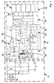
- an unearthed direct or alternating current network in the present case has two mains conductors 12, which are supplied with direct or alternating voltage (U DC , U AC ) by a mains voltage source 14.
- An unavoidable insulation resistance with ohmic and capacitive parts Re, Ce represents a certain network derivation between the network conductors 12 and earth E even when the network conditions are correct.
- the size of the ohmic part Re of this insulation resistance must be monitored. This is done by means of a pulse overlay.
- a monitoring device 16 is connected to the network conductors 12 and earth E via an ohmic network connection 24.
- FIG. 1 shows a measuring pulse with a pulse voltage value Up - pulse alternating voltage source 20 - via an ohmic network connection 24 between the network conductors 12 of the network 10 and earth E, a measuring current flows through the insulation resistance, which is proportional to the ohmic part Re after the transient process is inevitable insulation resistance (parallel connection of Re, Ce) between the network and earth and that of the internal resistance Ri of the measuring device (this includes the ohmic resistance of the Network connection).
- a voltage drop Um from which the ohmic part Re of the insulation resistance between the network 12 to be monitored and earth E can be calculated as follows:
- the transient process is based on the fact that when the measuring pulse is switched on, the capacitive part Ce of the insulation resistance first reaches the voltage value Up * Re / (Ri + Re) must be charged before the measuring current or the voltage drop derived therefrom (measuring current measured value) at Rm can be evaluated as a measure of the ohmic part of the insulation resistance.
- leakage direct currents superimpose the measurement result, namely the measured current measured value. Therefore, in the known pulse superimposition, two measuring pulses with different pulse voltage values are successively superimposed on the network and the associated measured current measured values are recorded. The difference between these measured current measured values eliminates the influence of the leakage direct currents.
- the value Um relevant for the determination of Re can be calculated from the two voltage drops Um1, Um2 at Rm as follows:
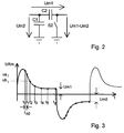
- the two voltages are subtracted in a known manner via a so-called sample & hold circuit according to FIG. 2.
- the first voltage Um1 is applied with the switch S2 closed, and the capacitors C1 and C2 charge up Voltage Um1 on.
- the switch S2 is opened and the second voltage Um2 is applied.
- the capacitor C1 is charged to the second voltage Um2, while the capacitor C2 maintains its previous voltage Um1.
- the differential voltage Um1-Um2 At the output of the sample and hold circuit - or at the input of a downstream measuring amplifier (see Fig. 1) - there is now the differential voltage Um1-Um2 to be evaluated.
- Ri represents the resistance of the parallel connection of Re and Ri. Since the measured variable Re can be infinitely large, tmess is 6 * Ri * Ce as the minimum duration to be set for the individual measuring pulses. For a full measuring cycle (difference formation of the measuring current measured values with two successive measuring pulses), at least twice the minimum duration applies.
- Adaptive measuring pulses are used, so to speak, the length of time of which is continuously adapted to the prevailing network conditions, namely the sizes of Ce and Re. In this way, optimally short measuring times can be achieved.
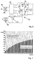
- FIG. 7 shows the clear temporal advantage of the method according to the invention over the prior art. While there is a constant measuring time tmess of 100% (set to Ce) according to the prior art, the measuring time according to the invention is reduced with decreasing Re to less than 10%. For usual sizes of Re, the measuring time tmeas is reduced to about 50% to 10%.
- FIGS. 3 and 4 for the case without interference frequencies (FIG. 3) and with interference frequencies (FIG. 4), it is shown how the transient processes of the voltage at Rm are monitored.
- the voltage rises steeply when Ce is charged (limited by the internal resistance Ri and slightly throttled by the choke 26), and then after an e-function to the final value Um1 or Um2 to be measured (measured current value in steady state) or to increase with a negative pulse voltage value.
- the measurement samples are detected by the fact that in certain mean measurement intervals between t0 and t1; t1 and t2 etc. arithmetic averaging of the voltage at Rm. In this way, interference frequencies can be eliminated by measurement. If the difference between two successive measurement samples Ua i and Ub i is sufficiently small or no longer measurable, the transient process is deemed to have ended and the measurement current measurement value Um1 or Um2 is recorded.
- the distances between the measuring times and the lengths of the mean value measuring intervals increase over time from a starting value t n0 or t n0 disturb .
- the starting value should be as small as possible so that short transient processes (Re and / or Ce small) can be detected as quickly as possible.
- the start value must be sufficiently large that long settling processes (Re and / or Ce large) are not immediately treated as finished because of the small differences in the test samples and the limited measurement resolution.
- a the still measurable minimum percentage change in measured value
- Cemax is the maximum expected system leakage capacitance (capacitive part Ce of the insulation resistance; Ce is, for example, about 150 ⁇ F).
- This start value must be increased to t nOstör if due to an existing interference frequency f stör of the value of t nOstör proves greater than t n0.
- a certain initial value of the interference frequency of, for example, 25 Hz is assumed - if the actual interference frequency should be different, in particular smaller, an automatic adjustment takes place in the course of the measuring method.
- the value of the ohmic insulation resistance calculated after the difference is only used as the correct end value when the end values determined in two successive measuring cycles or the difference values match. In this way, incorrect measurements can be avoided, which are based, for example, on the fact that the power supply ratio has changed in the meantime or that the actual interference frequency f interference deviates from the assumed initial value of 25 Hz by erroneous values.
- the starting value t n0stör (measuring interval for averaging the test sample) for the next measuring cycle each enlarged, as doubled by halving f disturb . This change continues until two identical end values are determined or until a minimum value of the interference frequency of, for example, 0.1 Hz has been reached. This automatically adjusts the measuring intervals to the actual interference frequency.
- the measuring time is extended in accordance with the interference frequency.
- the approximate size of the interference frequency is determined by measuring the time between maximum and minimum values at the end of a measuring cycle. If an actual interference frequency is greater than interference, then interference is adjusted accordingly and the mean value measurement interval or measurement time is shortened accordingly.
- a circuit part 18 of the measuring device 16 contains the above-mentioned parts 20, 22 and 24, which are connected in series between earth E and the line conductors 12. Between the network connection 24, which has four ohmic resistors in the present case, and the measuring resistor 22 or Rm a low-pass filter with a choke 26 and a capacitor 27 connected to earth E.
- the low-pass filter ensures that the higher-frequency interference components, as well as the mains frequency, are filtered out of the measuring branch.
- the voltage across the measuring resistor Rm or 22 is fed to a subtraction circuit 28 with an input-side resistor R and a subtraction element connected to it in the form of a sample and hold circuit which has two capacitors C1, C2 and a switch S2 bridging the capacitor C2 in the closed state.
- the subtractor which corresponds to the detail from FIG. 2 and operates accordingly, is connected on the output side to a measuring amplifier, not designated, from which the Measured value difference Um1-Um2 corresponding output signal U1 reaches an analog / digital converter A / D of a programmable microcontroller 34.
- the switch S2 controlled by the microcontroller 34 is initially closed until, after settling in, Um1 is stored in C2. Then S2 is opened and Um2 is stored in C1 after the transient has settled.
- a switch S1 bridging the capacitor C2 in the closed state, also controlled by the microcontroller 34, serves only the purpose of switching off the function of the subtractor in the event that a difference formation is not required, for example when none in an AC network due to missing converters or the like disturbing leakage direct currents occur in the network 12. Then circuit 28 can direct the voltage at Rm directly to microcontroller 34.
- the voltage across the measuring resistor Rm or 22 is also fed to an active rectifier circuit 30 with a measuring amplifier (not designated) and a rectifier element connected to it.
- Its output signal U2 which is also fed to the analog / digital converter A / D of the microcontroller 34, represents the rectified settling processes of the voltage at Rm. It is thus possible in principle with this signal U2 and the microcontroller 34 to monitor all positive and negative settling processes and the Determine transient conditions.
- the signal U2 falsified by leakage direct currents is only used to treat the negative transient processes, while the positive transient processes are tracked on the smaller difference signal U1 not falsified by leakage direct currents.
- the microcontroller 34 determines a transient state through the measurement sample comparisons, it passes a control signal S via a control line 36 to the pulse alternating voltage source 20, which in the present case is designed as a reversible voltage source. Depending on the control signal S, this alternately generates a positive and a negative DC voltage value (positive and negative pulse voltage values of the pulse AC voltage of the same size): the respective pulse voltage value is always retained until a further control signal S arrives.
- the pulse length of the measuring pulses is always adapted by the microcontroller 34 to the actual network conditions, which leads to an optimal shortening of the measuring times.
- the microcontroller 34 determines by evaluating U1 that two successive difference values or end values to be calculated from them for the ohmic insulation resistance Re are essentially the same, the last value of U1 for Re is evaluated and the value of Re is via a line connection 38 fed to an interface 40 with individual links 42.
- the individual elements can contain, for example, a trigger relay for an error, control buttons, a serial interface and the like.
- the mains voltage on the mains conductors 12 is detected via a differential amplifier 32 connected on the input side to the network coupling 24 and on the output side to the analog / digital converter A / D.
- This allows the microcontroller 34 to determine whether the measuring device is actually connected to the network to be monitored.
- the microcontroller 34 can thereby determine via the curve shape whether the measuring device is connected to a direct current network (with a two-pole network connection) or to an alternating current network (with a three-pole network connection).
- an automatic resistance correction can then be carried out. Instead, it is too possible to manually enter the type of network connection to the microcontroller 34 via the interface 40.
- a test switch Sp can disconnect the measuring resistor Rm or 22 from the choke 26 and instead connect the measuring resistor to an ohmic test resistor Rp connected to a control earth KE. This is designed so that it simulates a full earth fault of the network 10 to be monitored.
- FIG. 6 A practical exemplary embodiment of the pulse voltage source 20 designed as a reversible voltage source is shown in FIG. 6.
- a bridge circuit 46 consisting of four MOS field-effect transistors 48, 50, 52, 54 supplies via its bridge end points an output DC voltage which, depending on whether the diagonal transistors 48, 54 or 50, 52 are switched on, is either + 27V or -27V.
- the output DC voltage that can be switched between these values represents the pulse voltage values of the pulse AC voltage.
- the bridge center points are connected to the output of a DC voltage source 44. In the present case, this generates a DC voltage of 30V from a small DC input voltage of 12V via a galvanically isolating DC / DC converter 56, from which the stabilized DC voltage of 27V is generated.
- control electrodes of the field effect transistors are connected to the output of a control logic 58, which ensures the mutual switching and blocking of the diagonal field effect transistors.
- the control signal S coming from the microcontroller 34 via the control line 36, which is the control logic, serves as the input signal of the control logic 58 is fed via a galvanically isolating optocoupler 60.
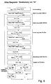
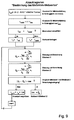
- FIGS. 8 and 9 represent essential steps in the overall sequence of the measuring method.
- a basic setting with default values for f disturb and Cemax is selected first. Then the flow chart of Fig. 9 is called for each of two successive measuring pulses in order to check the transient condition from two measurement samples obtained by averaging and for the two Measuring pulses determine the last measuring current measured value Um1 (first pulse), Um2 (second pulse) which is decisive in the transient state. A first insulation value Re1 for Re is then calculated from this. The whole process is then repeated to determine a second insulation value Re2 for Re. If the amount of Re1 and Re2 are completely or almost identical, it is assumed that the result is correct and the mean value of Re1, Re2 is calculated as a measure for Re.
- the starting value t n0 of the measuring intervals for generating the mean value of the measuring samples is first determined. Then two successive samples are compared. This process is repeated, increasing the measuring intervals, until two measuring samples match and the last measuring sample is adopted as the measuring current measured value Um.
Applications Claiming Priority (2)
| Application Number | Priority Date | Filing Date | Title |
|---|---|---|---|
| DE4339946A DE4339946A1 (de) | 1993-11-24 | 1993-11-24 | Verfahren und Einrichtung zur Isolationsüberwachung vom ungeerdeten Gleich- und Wechselstromnetzen |
| DE4339946 | 1993-11-24 |
Publications (2)
| Publication Number | Publication Date |
|---|---|
| EP0654673A1 true EP0654673A1 (fr) | 1995-05-24 |
| EP0654673B1 EP0654673B1 (fr) | 2002-07-10 |
Family
ID=6503264
Family Applications (1)
| Application Number | Title | Priority Date | Filing Date |
|---|---|---|---|
| EP94118162A Expired - Lifetime EP0654673B1 (fr) | 1993-11-24 | 1994-11-18 | Méthode et dispositif pour la surveillance de l'isolation dans des réseaux continus et alternatifs non mis à la terre |
Country Status (6)
| Country | Link |
|---|---|
| EP (1) | EP0654673B1 (fr) |
| AT (1) | ATE220462T1 (fr) |
| DE (2) | DE4339946A1 (fr) |
| DK (1) | DK0654673T3 (fr) |
| ES (1) | ES2179834T3 (fr) |
| PT (1) | PT654673E (fr) |
Cited By (26)
| Publication number | Priority date | Publication date | Assignee | Title |
|---|---|---|---|---|
| EP1586910A1 (fr) * | 2004-04-18 | 2005-10-19 | Deif A/S | Méthode et dispositif pour la surveillance de l'isolation |
| CN100401079C (zh) * | 2004-04-14 | 2008-07-09 | 山东大学 | 一种小接地电流系统单相接地选线方法 |
| US7609076B2 (en) * | 2006-07-03 | 2009-10-27 | Hanwa Electronic Ind. Co., Ltd. | Method of measuring characteristic impedance of electrostatic discharge protecting circuit and apparatus for realizing the same |
| EP2138854A1 (fr) | 2008-06-26 | 2009-12-30 | Deere & Company | Appareil et procédé pour déterminer la résistance d'isolation dans un système de bus électrique d'un véhicule mobile souterrain |
| CN101140317B (zh) * | 2006-09-06 | 2010-06-09 | 日立车辆能源株式会社 | 电池组总电压检测和漏泄检测装置 |
| WO2010133282A1 (fr) * | 2009-05-19 | 2010-11-25 | Abb Ag | Procédé et dispositif de surveillance de l'isolement de réseaux électriques de courant continu et de courant alternatif non reliés à la terre |
| EP2256506A1 (fr) * | 2009-05-27 | 2010-12-01 | DIPL.-ING. W. BENDER GmbH & Co. KG | Procédé et dispositif de surveillance de l'isolation de réseaux à courant continu et à courant alternatif non mis à la terre |
| ES2390148A1 (es) * | 2010-12-17 | 2012-11-07 | Zigor Corporacion, S. A. | Procedimiento y dispositivo para medir la resistencia de aislamiento eléctrico de una fuente de tensión continua. |
| WO2012160118A1 (fr) | 2011-05-24 | 2012-11-29 | Sma Solar Technology Ag | Contrôle d'isolation utilisant un signal de test à fréquence variable |
| WO2012164073A1 (fr) * | 2011-06-01 | 2012-12-06 | Commissariat à l'énergie atomique et aux énergies alternatives | Detection d'un defaut d'isolement |
| FR2976083A1 (fr) * | 2011-06-01 | 2012-12-07 | Commissariat Energie Atomique | Dispositif de detection d'un defaut d'isolement |
| CN103063950A (zh) * | 2012-12-19 | 2013-04-24 | 华中科技大学 | 一种忆阻器器件单元的电学特性测试系统及其测试方法 |
| EP2664932A1 (fr) * | 2012-05-15 | 2013-11-20 | Bender GmbH & Co. KG | Agencement de circuit de générateur d'impulsions et procédé de génération de signaux à impulsions pour la recherche d'erreurs d'isolation dans des réseaux informatiques |
| EP2672280A2 (fr) | 2012-06-06 | 2013-12-11 | Bender GmbH & Co. KG | Surveillance des défauts d'isolation avec affichage de la qualité des signaux |
| CN103884930A (zh) * | 2014-03-04 | 2014-06-25 | 王金全 | 一种基于绝缘监测的全桥不控整流器故障诊断方法 |
| WO2014128439A1 (fr) * | 2013-02-20 | 2014-08-28 | Viper Subsea Technology Limited | Rajeunissement de systèmes sous-marins de distribution d'électricité |
| WO2016131584A1 (fr) * | 2015-02-18 | 2016-08-25 | Sma Solar Technology Ag | Dispositif de détermination de la résistance d'isolation sur un générateur photovoltaïque et une installation photovoltaïque |
| EP3109647A1 (fr) | 2015-06-26 | 2016-12-28 | ABB Technology AG | Procédé et dispositif de mesure permettant de mesurer la résistance d'isolation d'un système photovoltaïque |
| WO2017161870A1 (fr) * | 2016-03-21 | 2017-09-28 | 华为技术有限公司 | Procédé et appareil de réglage de fréquence |
| EP3361270A1 (fr) * | 2017-02-09 | 2018-08-15 | ABB Schweiz AG | Procédé et dispositif pour surveiller rapidement l'isolation de dispositifs électriques ayant une large capacité par rapport à la terre |
| EP3413062A1 (fr) * | 2017-06-08 | 2018-12-12 | Bender GmbH & Co. KG | Procédé et dispositif de location de défauts d'isolement pour un système d'alimentation électrique non mis à la terre avec une durée adaptative d'un courant de test. |
| US10199810B2 (en) | 2013-02-20 | 2019-02-05 | Viper Innovations Ltd | Rejuvenation of subsea electrical cable insulation |
| DE102014205877B4 (de) | 2014-03-28 | 2019-08-22 | Continental Automotive Gmbh | Vorrichtung und Verfahren zur Überwachung einer elektrischen Isolation bei einem Bordnetz |
| EP3546957A1 (fr) * | 2018-03-28 | 2019-10-02 | Siemens Healthcare GmbH | Surveillance de l'efficacité de mise à la terre isolée |
| CN111426882A (zh) * | 2020-05-13 | 2020-07-17 | 常熟瑞特电气股份有限公司 | Rim型绝缘监测系统 |
| FR3109222A1 (fr) | 2020-04-14 | 2021-10-15 | Renault S.A.S. | Procédé de détection d’un défaut d’isolation électrique entre une source d’énergie électrique et une masse électrique |
Families Citing this family (21)
| Publication number | Priority date | Publication date | Assignee | Title |
|---|---|---|---|---|
| DE10106200C1 (de) * | 2001-02-10 | 2002-09-05 | Ean Elektroschaltanlagen Gmbh | Verfahren und Einrichtung zur Isolationsüberwachung ungeerdeter elektrischer Netze |
| DE10205381A1 (de) | 2002-02-09 | 2003-08-21 | Ballard Power Systems | Verfahren und Einrichtung zur Isolationsüberwachung eines Gleichstromnetzes |
| DE10212493A1 (de) | 2002-03-21 | 2003-10-02 | Ballard Power Systems | Anordnung zur Isolationsüberwachung eines elektrisch von Massepotential einer Einrichtung isolierten Gleichstromnetzes |
| DE10304234A1 (de) * | 2003-01-28 | 2004-08-05 | Volkswagen Ag | Verfahren und Vorrichtung zum Messen des Isolationswiderstandes in einem elektrischen Energie-System |
| EP1909369B1 (fr) | 2006-10-06 | 2020-05-20 | Schmidhauser AG | Agencement de commutation et procédé de surveillance d'isolation pour des applications de convertisseur en fonctionnement |
| DE102010030475A1 (de) | 2010-06-24 | 2012-01-19 | Robert Bosch Gmbh | Verfahren und Vorrichtung zur Bestimmung des Isolationswiderstandes eines ungeerdeten elektrischen Netzes |
| DE102010039692A1 (de) * | 2010-08-24 | 2012-03-01 | Dipl.-Ing. Walther Bender Gmbh & Co. Kg | Gerät zur Isolationsüberwachung eines nicht geerdeten Gleichspannungsnetzes, besonders einer Fotovoltaikanlage, und Anlage mit einem solchen Gerät |
| DE102010042394B4 (de) * | 2010-10-13 | 2022-02-03 | Vitesco Technologies GmbH | Verfahren und Schaltungsanordnung zur Überprüfung einer elektrischen Isolation |
| EP2570289B1 (fr) | 2011-09-16 | 2018-08-15 | Samsung SDI Co., Ltd. | Dispositif de détection de la résistance de l'isolement d'un système de batterie haute tension |
| DE102012019095B4 (de) * | 2012-09-27 | 2016-07-21 | E. Dold & Söhne KG | Einrichtung zur Überwachung eines Isolationswiderstandes von Netzen |
| EP2796886B1 (fr) | 2013-04-23 | 2017-09-06 | Technische Universität Graz | Agencement de circuit pour la localisation de défauts d'isolement |
| DE102013013950B4 (de) * | 2013-08-21 | 2020-08-06 | Audi Ag | Verfahren, Messanordnung und Messgerät zur Bestimmung von lsolationswiderständen von Einzelzellen einer Hochvoltbatterie |
| WO2015087098A1 (fr) | 2013-12-13 | 2015-06-18 | Prause József | Procédé pour mesurer la résistance d'isolation d'un réseau de puissance cc souterrain et pour localiser le défaut de mise à la terre, et dispositif d'injection de courant bipolaire |
| DE102014200288A1 (de) | 2014-01-10 | 2015-07-16 | Bender Gmbh & Co. Kg | Verfahren und Vorrichtung zur Isolationsüberwachung mit Alarm-Diagnose-Darstellung |
| DE102014016245A1 (de) | 2014-11-04 | 2015-06-11 | Daimler Ag | Verfahren zum Durchführen einer Isolationsprüfung an einer elektrischen Anlage eines elektrisch angetriebenen Fahrzeugs |
| DE102015016000A1 (de) | 2015-12-10 | 2016-08-11 | Daimler Ag | Schaltungsanordnung für ein Kraftfahrzeug und Verfahren zur Entladung von Y-Kapazitäten in Fahrzeugen mit Hochvoltbordnetz |
| CN114729961A (zh) | 2019-11-28 | 2022-07-08 | Ls电气株式会社 | 绝缘监控装置以及该绝缘监控装置的控制方法 |
| AT523526B1 (de) | 2020-04-10 | 2021-09-15 | Seibt Kristl & Co Gmbh | Verfahren, Vorrichtung und System zur Bestimmung eines Kapazitätswertes einer Erdungskapazität eines ungeerdeten Stromnetzes |
| DE102020120433B3 (de) | 2020-08-03 | 2021-10-28 | Bender Gmbh & Co. Kg | Sensor für ein elektrisches Bordnetz |
| DE102021203919A1 (de) | 2021-04-20 | 2022-10-20 | Vitesco Technologies GmbH | Isolationswächter zum Erfassen eines Isolationsfehlers einer elektrischen Isolierung eines elektrischen Systems |
| DE102022100846A1 (de) | 2022-01-14 | 2023-07-20 | Preh Gmbh | Verfahren und Vorrichtung zum Laden einer Hochvoltbatterie |
Citations (5)
| Publication number | Priority date | Publication date | Assignee | Title |
|---|---|---|---|---|
| DE2509661A1 (de) * | 1975-03-06 | 1976-09-16 | Gerd Dr Ing Harms | Einrichtung zur messung des isolationswiderstandes von ungeerdeten gleichstromnetzen |
| DE2545325A1 (de) * | 1975-10-09 | 1977-04-14 | Siemens Ag | Schaltungsanordnung zur messung des isolationswiderstandes erdfreier starkstromschaltungen |
| DE2545315A1 (de) * | 1975-10-09 | 1977-04-14 | Siemens Ag | Schaltungsanordnung zur erdschlussueberwachung einer erdfreien gleichstromschaltung |
| DE2618303A1 (de) * | 1976-04-27 | 1977-11-17 | Bureaux De Const De Relais Ele | Verfahren und vorrichtung zur isolationsueberwachung |
| DE3346387A1 (de) * | 1983-12-22 | 1985-07-04 | Standard Elektrik Lorenz Ag, 7000 Stuttgart | Schaltungsanordnung zur erd- und koerperschlussueberwachung |
Family Cites Families (4)
| Publication number | Priority date | Publication date | Assignee | Title |
|---|---|---|---|---|
| DE2357081C3 (de) * | 1973-11-15 | 1979-09-13 | Gerd Dr.-Ing. 3167 Burgdorf Harms | Verfahren und Einrichtung zur Messung des Isolationswiderstandes von ungeerdeten Gleichstromnetzen |
| CH579840A5 (fr) * | 1974-11-14 | 1976-09-15 | Bbc Brown Boveri & Cie | |
| DE2717158A1 (de) * | 1977-04-19 | 1978-11-02 | Bureaux De Const De Relais Ele | Verfahren und einrichtung zum bestimmen des isolationswiderstandes insbesondere von wechselstromnetzen mit oder ohne gleichrichter |
| SU1323983A1 (ru) * | 1986-01-23 | 1987-07-15 | Войсковая часть 27177 | Устройство дл измерени сопротивлени изол ции электрических сетей посто нного тока |
-
1993
- 1993-11-24 DE DE4339946A patent/DE4339946A1/de not_active Ceased
-
1994
- 1994-11-18 DK DK94118162T patent/DK0654673T3/da active
- 1994-11-18 ES ES94118162T patent/ES2179834T3/es not_active Expired - Lifetime
- 1994-11-18 EP EP94118162A patent/EP0654673B1/fr not_active Expired - Lifetime
- 1994-11-18 AT AT94118162T patent/ATE220462T1/de active
- 1994-11-18 DE DE59410152T patent/DE59410152D1/de not_active Expired - Lifetime
- 1994-11-18 PT PT94118162T patent/PT654673E/pt unknown
Patent Citations (5)
| Publication number | Priority date | Publication date | Assignee | Title |
|---|---|---|---|---|
| DE2509661A1 (de) * | 1975-03-06 | 1976-09-16 | Gerd Dr Ing Harms | Einrichtung zur messung des isolationswiderstandes von ungeerdeten gleichstromnetzen |
| DE2545325A1 (de) * | 1975-10-09 | 1977-04-14 | Siemens Ag | Schaltungsanordnung zur messung des isolationswiderstandes erdfreier starkstromschaltungen |
| DE2545315A1 (de) * | 1975-10-09 | 1977-04-14 | Siemens Ag | Schaltungsanordnung zur erdschlussueberwachung einer erdfreien gleichstromschaltung |
| DE2618303A1 (de) * | 1976-04-27 | 1977-11-17 | Bureaux De Const De Relais Ele | Verfahren und vorrichtung zur isolationsueberwachung |
| DE3346387A1 (de) * | 1983-12-22 | 1985-07-04 | Standard Elektrik Lorenz Ag, 7000 Stuttgart | Schaltungsanordnung zur erd- und koerperschlussueberwachung |
Cited By (51)
| Publication number | Priority date | Publication date | Assignee | Title |
|---|---|---|---|---|
| CN100401079C (zh) * | 2004-04-14 | 2008-07-09 | 山东大学 | 一种小接地电流系统单相接地选线方法 |
| EP1586910A1 (fr) * | 2004-04-18 | 2005-10-19 | Deif A/S | Méthode et dispositif pour la surveillance de l'isolation |
| US7609076B2 (en) * | 2006-07-03 | 2009-10-27 | Hanwa Electronic Ind. Co., Ltd. | Method of measuring characteristic impedance of electrostatic discharge protecting circuit and apparatus for realizing the same |
| CN101140317B (zh) * | 2006-09-06 | 2010-06-09 | 日立车辆能源株式会社 | 电池组总电压检测和漏泄检测装置 |
| EP2138854A1 (fr) | 2008-06-26 | 2009-12-30 | Deere & Company | Appareil et procédé pour déterminer la résistance d'isolation dans un système de bus électrique d'un véhicule mobile souterrain |
| WO2010133282A1 (fr) * | 2009-05-19 | 2010-11-25 | Abb Ag | Procédé et dispositif de surveillance de l'isolement de réseaux électriques de courant continu et de courant alternatif non reliés à la terre |
| CN102439464A (zh) * | 2009-05-19 | 2012-05-02 | Abb股份公司 | 用于绝缘监测未接地的直流电网和交流电网的方法和装置 |
| US8994379B2 (en) | 2009-05-19 | 2015-03-31 | Abb Ag | Method and device for insulation monitoring of non-grounded electrical DC and AC grids |
| WO2010136284A1 (fr) * | 2009-05-27 | 2010-12-02 | Dipl.-Ing W. Bender Gmbh & Co. Kg | Procédé et dispositif de surveillance de l'isolation de réseaux à tension continue et/ou alternative non mis à la terre |
| US9069025B2 (en) | 2009-05-27 | 2015-06-30 | Bender Gmbh & Co. Kg | Method and device for monitoring the insulation of ungrounded DC and AC voltage networks |
| EP2256506A1 (fr) * | 2009-05-27 | 2010-12-01 | DIPL.-ING. W. BENDER GmbH & Co. KG | Procédé et dispositif de surveillance de l'isolation de réseaux à courant continu et à courant alternatif non mis à la terre |
| ES2390148A1 (es) * | 2010-12-17 | 2012-11-07 | Zigor Corporacion, S. A. | Procedimiento y dispositivo para medir la resistencia de aislamiento eléctrico de una fuente de tensión continua. |
| WO2012160118A1 (fr) | 2011-05-24 | 2012-11-29 | Sma Solar Technology Ag | Contrôle d'isolation utilisant un signal de test à fréquence variable |
| DE102011050590A1 (de) | 2011-05-24 | 2012-11-29 | Sma Solar Technology Ag | Isolationsüberwachung mit einem Prüfsignal variabler Frequenz |
| CN103547932B (zh) * | 2011-05-24 | 2016-09-21 | 艾思玛太阳能技术股份公司 | 使用可变频率的测试信号的隔离监控 |
| US9720025B2 (en) | 2011-05-24 | 2017-08-01 | Sma Solar Technology Ag | Isolation monitoring using a test signal of variable frequency |
| WO2012164073A1 (fr) * | 2011-06-01 | 2012-12-06 | Commissariat à l'énergie atomique et aux énergies alternatives | Detection d'un defaut d'isolement |
| FR2976083A1 (fr) * | 2011-06-01 | 2012-12-07 | Commissariat Energie Atomique | Dispositif de detection d'un defaut d'isolement |
| US9322867B2 (en) | 2011-06-01 | 2016-04-26 | Commissariat A L'energie Atomique Et Aux Energies Alternatives | Detection of an insulation defect |
| EP2664932A1 (fr) * | 2012-05-15 | 2013-11-20 | Bender GmbH & Co. KG | Agencement de circuit de générateur d'impulsions et procédé de génération de signaux à impulsions pour la recherche d'erreurs d'isolation dans des réseaux informatiques |
| CN103427797B (zh) * | 2012-05-15 | 2016-03-09 | 本德尔有限两合公司 | 生成脉冲信号的脉冲发生器电路设备和方法 |
| CN103427797A (zh) * | 2012-05-15 | 2013-12-04 | 本德尔有限两合公司 | 脉冲发生器电路设备和生成脉冲信号的方法 |
| DE102012208111C5 (de) * | 2012-05-15 | 2016-05-12 | Bender Gmbh & Co. Kg | Pulsgenerator-Schaltungsanordnung und Verfahren zur Erzeugung von Pulssignalen für die Isolationsfehlersuche in IT-Netzen |
| US9543756B2 (en) | 2012-05-15 | 2017-01-10 | Bender Gmbh & Co. Kg | Pulse generator circuit arrangement and method for generating pulsed signals for insulation fault location in IT networks |
| DE102012209586A1 (de) | 2012-06-06 | 2013-12-12 | Bender Gmbh & Co. Kg | Isolationsfehlerüberwachung mit Signalqualitätsanzeige |
| EP2672280A3 (fr) * | 2012-06-06 | 2017-05-24 | Bender GmbH & Co. KG | Surveillance des défauts d'isolation avec affichage de la qualité des signaux |
| EP2672280A2 (fr) | 2012-06-06 | 2013-12-11 | Bender GmbH & Co. KG | Surveillance des défauts d'isolation avec affichage de la qualité des signaux |
| CN103063950A (zh) * | 2012-12-19 | 2013-04-24 | 华中科技大学 | 一种忆阻器器件单元的电学特性测试系统及其测试方法 |
| CN103063950B (zh) * | 2012-12-19 | 2015-05-20 | 华中科技大学 | 一种忆阻器器件单元的电学特性测试方法 |
| GB2522351B (en) * | 2013-02-20 | 2015-09-02 | Viper Subsea Technology Ltd | Rejuvenation of subsea electrical distribution systems |
| US10199810B2 (en) | 2013-02-20 | 2019-02-05 | Viper Innovations Ltd | Rejuvenation of subsea electrical cable insulation |
| US11276994B2 (en) | 2013-02-20 | 2022-03-15 | Viper Innovations Ltd | Rejuvenation of subsea electrical cable insulation |
| GB2522351A (en) * | 2013-02-20 | 2015-07-22 | Viper Subsea Technology Ltd | Rejuvenation of subsea electrical distribution systems |
| WO2014128439A1 (fr) * | 2013-02-20 | 2014-08-28 | Viper Subsea Technology Limited | Rajeunissement de systèmes sous-marins de distribution d'électricité |
| CN103884930A (zh) * | 2014-03-04 | 2014-06-25 | 王金全 | 一种基于绝缘监测的全桥不控整流器故障诊断方法 |
| DE102014205877B4 (de) | 2014-03-28 | 2019-08-22 | Continental Automotive Gmbh | Vorrichtung und Verfahren zur Überwachung einer elektrischen Isolation bei einem Bordnetz |
| CN107110899A (zh) * | 2015-02-18 | 2017-08-29 | 艾思玛太阳能技术股份公司 | 光伏系统和用于在pv发电机上进行绝缘电阻测定的装置 |
| US10197608B2 (en) | 2015-02-18 | 2019-02-05 | Sma Solar Technology Ag | Apparatus for determining insulation resistance at a PV generator, and photovoltaic installation |
| WO2016131584A1 (fr) * | 2015-02-18 | 2016-08-25 | Sma Solar Technology Ag | Dispositif de détermination de la résistance d'isolation sur un générateur photovoltaïque et une installation photovoltaïque |
| EP3109647A1 (fr) | 2015-06-26 | 2016-12-28 | ABB Technology AG | Procédé et dispositif de mesure permettant de mesurer la résistance d'isolation d'un système photovoltaïque |
| US11150284B2 (en) | 2016-03-21 | 2021-10-19 | Huawei Technologies Co., Ltd. | Frequency regulation method and apparatus |
| WO2017161870A1 (fr) * | 2016-03-21 | 2017-09-28 | 华为技术有限公司 | Procédé et appareil de réglage de fréquence |
| EP3361270A1 (fr) * | 2017-02-09 | 2018-08-15 | ABB Schweiz AG | Procédé et dispositif pour surveiller rapidement l'isolation de dispositifs électriques ayant une large capacité par rapport à la terre |
| EP3413062A1 (fr) * | 2017-06-08 | 2018-12-12 | Bender GmbH & Co. KG | Procédé et dispositif de location de défauts d'isolement pour un système d'alimentation électrique non mis à la terre avec une durée adaptative d'un courant de test. |
| CN109031039A (zh) * | 2017-06-08 | 2018-12-18 | 本德尔有限两合公司 | 用于不接地供电系统的绝缘故障定位方法和系统 |
| US10598720B2 (en) | 2017-06-08 | 2020-03-24 | Bender Gmbh & Co. Kg | Method for insulation fault location and an insulation fault location system for an ungrounded power supply system |
| EP3546957A1 (fr) * | 2018-03-28 | 2019-10-02 | Siemens Healthcare GmbH | Surveillance de l'efficacité de mise à la terre isolée |
| US10725120B2 (en) | 2018-03-28 | 2020-07-28 | Siemens Healthcare Gmbh | Isolated grounding effectiveness monitor |
| FR3109222A1 (fr) | 2020-04-14 | 2021-10-15 | Renault S.A.S. | Procédé de détection d’un défaut d’isolation électrique entre une source d’énergie électrique et une masse électrique |
| WO2021209207A1 (fr) | 2020-04-14 | 2021-10-21 | Renault S.A.S | Procede de detection d'un defaut d'isolation electrique entre une source d'energie electrique et une masse electrique |
| CN111426882A (zh) * | 2020-05-13 | 2020-07-17 | 常熟瑞特电气股份有限公司 | Rim型绝缘监测系统 |
Also Published As
| Publication number | Publication date |
|---|---|
| DE4339946A1 (de) | 1995-06-01 |
| DE59410152D1 (de) | 2002-08-14 |
| PT654673E (pt) | 2002-11-29 |
| ES2179834T3 (es) | 2003-02-01 |
| DK0654673T3 (da) | 2002-11-04 |
| EP0654673B1 (fr) | 2002-07-10 |
| ATE220462T1 (de) | 2002-07-15 |
Similar Documents
| Publication | Publication Date | Title |
|---|---|---|
| EP0654673B1 (fr) | Méthode et dispositif pour la surveillance de l'isolation dans des réseaux continus et alternatifs non mis à la terre | |
| EP2433147B1 (fr) | Procédé et processus pour la surveillance de l'isolation dans des réseaux continus et alternatifs non mis à la terre | |
| DE10106200C1 (de) | Verfahren und Einrichtung zur Isolationsüberwachung ungeerdeter elektrischer Netze | |
| DE19714972A1 (de) | Einrichtung zur Überwachung der Applikation einer Neutralelektrode | |
| WO2009043772A1 (fr) | Montage destiné à surveiller une isolation électrique | |
| DE10205381A1 (de) | Verfahren und Einrichtung zur Isolationsüberwachung eines Gleichstromnetzes | |
| EP2808688A1 (fr) | Procédé de détermination d'un paramètre d'un réseau électrique | |
| EP1307753B1 (fr) | Procede et dispositif pour reconnaitre et localiser des defauts a la terre monopolaires a valeur ohmique elevee | |
| AT402770B (de) | Verfahren zum überwachen eines drehstromnetzes auf eine abstimmungsänderung der erdschlusslöschspule | |
| DE2357361A1 (de) | Elektrischer schaltkreis zur erfassung von erdungsfehlern | |
| DE4109586A1 (de) | Schaltungsanordnung zur isolationsueberwachung ungeerdeter niederspannungsnetze | |
| DE2545325C3 (de) | Schaltungsanordnung zur Messung des Isolationswiderstandes erdfreier Starkstromschaltungen | |
| WO2015158569A1 (fr) | Procédé et dispositif permettant de déterminer une résistance d'isolement et système de batterie haute tension munie dudit dispositif | |
| DE69405998T3 (de) | Elektrisches testgerät | |
| EP3281022B1 (fr) | Bloc électrique ainsi que circuit de mesure et procédé de mesure pour la surveillance d'un composant du bloc électrique | |
| EP0165512B1 (fr) | Procédé d'évaluation de la différence entre une tension alternative et une deuxième tension et dispositif de mesure pour son application | |
| DE2731453B2 (de) | Erdschlußdetektor | |
| DE102019132071B4 (de) | Vorrichtung zum Überwachen eines Versorgungsnetzes | |
| DE2312378B2 (de) | Anordnung zum Wiedergewinnen eines von Störspitzen verzerrten Signals | |
| DE3513849C2 (fr) | ||
| DE3915880C2 (fr) | ||
| EP3971590B1 (fr) | Agencement électrique de mesure et procédé de surveillance continue d'une résistance de conducteur de protection | |
| EP3797408B1 (fr) | Dispositif, procédé et module de commande pour la surveillance d'une ligne à deux fils | |
| EP3832823B1 (fr) | Procédé et dispositifs de génération des informations relatives au défaut à la terre | |
| DE2717158A1 (de) | Verfahren und einrichtung zum bestimmen des isolationswiderstandes insbesondere von wechselstromnetzen mit oder ohne gleichrichter |
Legal Events
| Date | Code | Title | Description |
|---|---|---|---|
| PUAI | Public reference made under article 153(3) epc to a published international application that has entered the european phase |
Free format text: ORIGINAL CODE: 0009012 |
|
| AK | Designated contracting states |
Kind code of ref document: A1 Designated state(s): AT BE CH DE DK ES FR GB GR IE IT LI LU MC NL PT SE |
|
| 17P | Request for examination filed |
Effective date: 19951103 |
|
| 17Q | First examination report despatched |
Effective date: 19990302 |
|
| GRAG | Despatch of communication of intention to grant |
Free format text: ORIGINAL CODE: EPIDOS AGRA |
|
| GRAG | Despatch of communication of intention to grant |
Free format text: ORIGINAL CODE: EPIDOS AGRA |
|
| GRAH | Despatch of communication of intention to grant a patent |
Free format text: ORIGINAL CODE: EPIDOS IGRA |
|
| GRAH | Despatch of communication of intention to grant a patent |
Free format text: ORIGINAL CODE: EPIDOS IGRA |
|
| GRAA | (expected) grant |
Free format text: ORIGINAL CODE: 0009210 |
|
| AK | Designated contracting states |
Kind code of ref document: B1 Designated state(s): AT BE CH DE DK ES FR GB GR IE IT LI LU MC NL PT SE |
|
| REF | Corresponds to: |
Ref document number: 220462 Country of ref document: AT Date of ref document: 20020715 Kind code of ref document: T |
|
| REG | Reference to a national code |
Ref country code: GB Ref legal event code: FG4D Free format text: NOT ENGLISH |
|
| REG | Reference to a national code |
Ref country code: CH Ref legal event code: EP |
|
| REG | Reference to a national code |
Ref country code: IE Ref legal event code: FG4D Free format text: GERMAN |
|
| REF | Corresponds to: |
Ref document number: 59410152 Country of ref document: DE Date of ref document: 20020814 |
|
| GBT | Gb: translation of ep patent filed (gb section 77(6)(a)/1977) |
Effective date: 20021016 |
|
| REG | Reference to a national code |
Ref country code: PT Ref legal event code: SC4A Free format text: AVAILABILITY OF NATIONAL TRANSLATION Effective date: 20021009 |
|
| REG | Reference to a national code |
Ref country code: GR Ref legal event code: EP Ref document number: 20020403310 Country of ref document: GR |
|
| ET | Fr: translation filed | ||
| REG | Reference to a national code |
Ref country code: ES Ref legal event code: FG2A Ref document number: 2179834 Country of ref document: ES Kind code of ref document: T3 |
|
| PLBE | No opposition filed within time limit |
Free format text: ORIGINAL CODE: 0009261 |
|
| STAA | Information on the status of an ep patent application or granted ep patent |
Free format text: STATUS: NO OPPOSITION FILED WITHIN TIME LIMIT |
|
| 26N | No opposition filed |
Effective date: 20030411 |
|
| PGFP | Annual fee paid to national office [announced via postgrant information from national office to epo] |
Ref country code: MC Payment date: 20110523 Year of fee payment: 17 Ref country code: SE Payment date: 20110523 Year of fee payment: 17 Ref country code: PT Payment date: 20110511 Year of fee payment: 17 Ref country code: IE Payment date: 20110530 Year of fee payment: 17 Ref country code: GR Payment date: 20110525 Year of fee payment: 17 Ref country code: LU Payment date: 20110525 Year of fee payment: 17 Ref country code: CH Payment date: 20110525 Year of fee payment: 17 |
|
| PGFP | Annual fee paid to national office [announced via postgrant information from national office to epo] |
Ref country code: BE Payment date: 20110525 Year of fee payment: 17 Ref country code: AT Payment date: 20110520 Year of fee payment: 17 Ref country code: DK Payment date: 20110525 Year of fee payment: 17 |
|
| REG | Reference to a national code |
Ref country code: PT Ref legal event code: MM4A Free format text: LAPSE DUE TO NON-PAYMENT OF FEES Effective date: 20120518 |
|
| BERE | Be: lapsed |
Owner name: WALTHER *BENDER G.M.B.H. & CO. K.G. Effective date: 20111130 |
|
| PG25 | Lapsed in a contracting state [announced via postgrant information from national office to epo] |
Ref country code: MC Free format text: LAPSE BECAUSE OF NON-PAYMENT OF DUE FEES Effective date: 20111130 |
|
| REG | Reference to a national code |
Ref country code: CH Ref legal event code: PL |
|
| REG | Reference to a national code |
Ref country code: DK Ref legal event code: EBP |
|
| REG | Reference to a national code |
Ref country code: SE Ref legal event code: EUG |
|
| REG | Reference to a national code |
Ref country code: GR Ref legal event code: ML Ref document number: 20020403310 Country of ref document: GR Effective date: 20120605 |
|
| PG25 | Lapsed in a contracting state [announced via postgrant information from national office to epo] |
Ref country code: LI Free format text: LAPSE BECAUSE OF NON-PAYMENT OF DUE FEES Effective date: 20111130 Ref country code: CH Free format text: LAPSE BECAUSE OF NON-PAYMENT OF DUE FEES Effective date: 20111130 |
|
| REG | Reference to a national code |
Ref country code: IE Ref legal event code: MM4A |
|
| PG25 | Lapsed in a contracting state [announced via postgrant information from national office to epo] |
Ref country code: PT Free format text: LAPSE BECAUSE OF NON-PAYMENT OF DUE FEES Effective date: 20120518 Ref country code: BE Free format text: LAPSE BECAUSE OF NON-PAYMENT OF DUE FEES Effective date: 20111130 Ref country code: GR Free format text: LAPSE BECAUSE OF NON-PAYMENT OF DUE FEES Effective date: 20120605 |
|
| PG25 | Lapsed in a contracting state [announced via postgrant information from national office to epo] |
Ref country code: IE Free format text: LAPSE BECAUSE OF NON-PAYMENT OF DUE FEES Effective date: 20111118 Ref country code: DK Free format text: LAPSE BECAUSE OF NON-PAYMENT OF DUE FEES Effective date: 20111130 Ref country code: SE Free format text: LAPSE BECAUSE OF NON-PAYMENT OF DUE FEES Effective date: 20111119 |
|
| REG | Reference to a national code |
Ref country code: AT Ref legal event code: MM01 Ref document number: 220462 Country of ref document: AT Kind code of ref document: T Effective date: 20111118 |
|
| PG25 | Lapsed in a contracting state [announced via postgrant information from national office to epo] |
Ref country code: AT Free format text: LAPSE BECAUSE OF NON-PAYMENT OF DUE FEES Effective date: 20111118 |
|
| PG25 | Lapsed in a contracting state [announced via postgrant information from national office to epo] |
Ref country code: LU Free format text: LAPSE BECAUSE OF NON-PAYMENT OF DUE FEES Effective date: 20111118 |
|
| PGFP | Annual fee paid to national office [announced via postgrant information from national office to epo] |
Ref country code: GB Payment date: 20140528 Year of fee payment: 20 |
|
| REG | Reference to a national code |
Ref country code: FR Ref legal event code: ST Effective date: 20140731 |
|
| PGFP | Annual fee paid to national office [announced via postgrant information from national office to epo] |
Ref country code: NL Payment date: 20140528 Year of fee payment: 20 Ref country code: DE Payment date: 20140521 Year of fee payment: 20 Ref country code: IT Payment date: 20140528 Year of fee payment: 20 Ref country code: ES Payment date: 20140528 Year of fee payment: 20 |
|
| REG | Reference to a national code |
Ref country code: FR Ref legal event code: D3 Effective date: 20140730 |
|
| REG | Reference to a national code |
Ref country code: DE Ref legal event code: R071 Ref document number: 59410152 Country of ref document: DE |
|
| REG | Reference to a national code |
Ref country code: NL Ref legal event code: V4 Effective date: 20141118 |
|
| PGFP | Annual fee paid to national office [announced via postgrant information from national office to epo] |
Ref country code: FR Payment date: 20140528 Year of fee payment: 20 |
|
| PGRI | Patent reinstated in contracting state [announced from national office to epo] |
Ref country code: FR Effective date: 20140730 |
|
| REG | Reference to a national code |
Ref country code: GB Ref legal event code: PE20 Expiry date: 20141117 |
|
| PG25 | Lapsed in a contracting state [announced via postgrant information from national office to epo] |
Ref country code: GB Free format text: LAPSE BECAUSE OF EXPIRATION OF PROTECTION Effective date: 20141117 |
|
| REG | Reference to a national code |
Ref country code: ES Ref legal event code: FD2A Effective date: 20150327 |
|
| PG25 | Lapsed in a contracting state [announced via postgrant information from national office to epo] |
Ref country code: ES Free format text: LAPSE BECAUSE OF EXPIRATION OF PROTECTION Effective date: 20141119 |