EP0653193A1 - Vorrichtung zur subkutanen Lokalisierung einer medizinischen Prothese und entsprechende Prothese - Google Patents
Vorrichtung zur subkutanen Lokalisierung einer medizinischen Prothese und entsprechende Prothese Download PDFInfo
- Publication number
- EP0653193A1 EP0653193A1 EP94402537A EP94402537A EP0653193A1 EP 0653193 A1 EP0653193 A1 EP 0653193A1 EP 94402537 A EP94402537 A EP 94402537A EP 94402537 A EP94402537 A EP 94402537A EP 0653193 A1 EP0653193 A1 EP 0653193A1
- Authority
- EP
- European Patent Office
- Prior art keywords
- nail
- envelope
- catheter
- tubular element
- patient
- Prior art date
- Legal status (The legal status is an assumption and is not a legal conclusion. Google has not performed a legal analysis and makes no representation as to the accuracy of the status listed.)
- Withdrawn
Links
Images
Classifications
-
- A—HUMAN NECESSITIES
- A61—MEDICAL OR VETERINARY SCIENCE; HYGIENE
- A61F—FILTERS IMPLANTABLE INTO BLOOD VESSELS; PROSTHESES; DEVICES PROVIDING PATENCY TO, OR PREVENTING COLLAPSING OF, TUBULAR STRUCTURES OF THE BODY, e.g. STENTS; ORTHOPAEDIC, NURSING OR CONTRACEPTIVE DEVICES; FOMENTATION; TREATMENT OR PROTECTION OF EYES OR EARS; BANDAGES, DRESSINGS OR ABSORBENT PADS; FIRST-AID KITS
- A61F2/00—Filters implantable into blood vessels; Prostheses, i.e. artificial substitutes or replacements for parts of the body; Appliances for connecting them with the body; Devices providing patency to, or preventing collapsing of, tubular structures of the body, e.g. stents
- A61F2/95—Instruments specially adapted for placement or removal of stents or stent-grafts
-
- A—HUMAN NECESSITIES
- A61—MEDICAL OR VETERINARY SCIENCE; HYGIENE
- A61F—FILTERS IMPLANTABLE INTO BLOOD VESSELS; PROSTHESES; DEVICES PROVIDING PATENCY TO, OR PREVENTING COLLAPSING OF, TUBULAR STRUCTURES OF THE BODY, e.g. STENTS; ORTHOPAEDIC, NURSING OR CONTRACEPTIVE DEVICES; FOMENTATION; TREATMENT OR PROTECTION OF EYES OR EARS; BANDAGES, DRESSINGS OR ABSORBENT PADS; FIRST-AID KITS
- A61F2/00—Filters implantable into blood vessels; Prostheses, i.e. artificial substitutes or replacements for parts of the body; Appliances for connecting them with the body; Devices providing patency to, or preventing collapsing of, tubular structures of the body, e.g. stents
- A61F2/01—Filters implantable into blood vessels
- A61F2/0105—Open ended, i.e. legs gathered only at one side
-
- A—HUMAN NECESSITIES
- A61—MEDICAL OR VETERINARY SCIENCE; HYGIENE
- A61F—FILTERS IMPLANTABLE INTO BLOOD VESSELS; PROSTHESES; DEVICES PROVIDING PATENCY TO, OR PREVENTING COLLAPSING OF, TUBULAR STRUCTURES OF THE BODY, e.g. STENTS; ORTHOPAEDIC, NURSING OR CONTRACEPTIVE DEVICES; FOMENTATION; TREATMENT OR PROTECTION OF EYES OR EARS; BANDAGES, DRESSINGS OR ABSORBENT PADS; FIRST-AID KITS
- A61F2/00—Filters implantable into blood vessels; Prostheses, i.e. artificial substitutes or replacements for parts of the body; Appliances for connecting them with the body; Devices providing patency to, or preventing collapsing of, tubular structures of the body, e.g. stents
- A61F2/01—Filters implantable into blood vessels
- A61F2/011—Instruments for their placement or removal
-
- A—HUMAN NECESSITIES
- A61—MEDICAL OR VETERINARY SCIENCE; HYGIENE
- A61F—FILTERS IMPLANTABLE INTO BLOOD VESSELS; PROSTHESES; DEVICES PROVIDING PATENCY TO, OR PREVENTING COLLAPSING OF, TUBULAR STRUCTURES OF THE BODY, e.g. STENTS; ORTHOPAEDIC, NURSING OR CONTRACEPTIVE DEVICES; FOMENTATION; TREATMENT OR PROTECTION OF EYES OR EARS; BANDAGES, DRESSINGS OR ABSORBENT PADS; FIRST-AID KITS
- A61F2230/00—Geometry of prostheses classified in groups A61F2/00 - A61F2/26 or A61F2/82 or A61F9/00 or A61F11/00 or subgroups thereof
- A61F2230/0002—Two-dimensional shapes, e.g. cross-sections
- A61F2230/0028—Shapes in the form of latin or greek characters
- A61F2230/005—Rosette-shaped, e.g. star-shaped
Definitions
- the invention relates to a device for subcutaneous identification of a medical prosthesis comprising a perforable tubular element and implantable in the body of a patient, the device of the invention being particularly applicable to identification by palpation, through the patient's skin, a catheter or equivalent usually associated with a temporary blood filter.
- the catheters, (or flexible rods) to which they are generally fixed to allow particularly their removal have particular characteristics.
- the practitioner is now offered the possibility, for example when implantation of the filter must be prolonged for several weeks, to cut the catheter to length, after having implanted the filter. , so that the proximal end of this catheter (opposite end to the one carrying the filter) does not open to the outside of the patient's body.
- the practitioner fixes around the catheter a locating member which he will place with said end of the catheter in a small housing which he has provided under the skin of the patient, in the immediate vicinity of the access route. which was used to implant the filter. After which it only remains to suture the flesh, leaving the filter and its catheter buried, with its locating organ.
- the filter When the filter has to be removed, it will then suffice for the practitioner to detect, for example by palpation, the location of the locating member to which he can access by a new small incision, this allowing him to access the catheter which he will be able to remove or even move.
- Patent application FR 9000769 (or the corresponding American patent 07/731536 of July 17, 1991) provides an example. Another example can be found in US Patent 4,834,713.
- this envelope will contain an internal ring not intended to be deformed and having a wall surrounding an internal passage coaxial with that of said envelope, this ring being arranged so that said locking nail passes through its wall to perforate the tubular element.
- both the nail and the ring will be completely coated by the envelope.
- they can in particular be made of metal.
- said nail may moreover have a cross section clearly smaller than the internal diameter of the catheter, so as in particular not to weaken the support catheter.
- the device will preferably be devoid of means for anchoring to the body of this patient, in particular avoiding that flesh can be pulled or even torn off.
- the locating device of the invention can very particularly be associated with a temporary blood filtration instrument, only this embodiment will be described below, the indications contained in the present application as well as the technical knowledge of the person skilled in the art. profession should allow it to easily adapt the device for use, for example, on an aterectomy device, of the type of that of publication EP 92 402098.5.
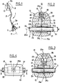
- FIG. 1 a diagrammatic illustration is thus shown of a temporary filtration unit 1, entirely conventional in itself, comprising a catheter 3 (or any equivalent flexible, flexible means, such as a rod or a filament) carrying, fixed to him on the side of his end distal 3a, a blood filter 5, which in this case consists of a connecting head 7, for example crimped at the end 3a and in which are joined a series of elongated legs 9 extending essentially in the general direction 11 of the device.
- these tabs are expandable radially to the axis 11, so that from their free end opposite the head 7, they deploy in a substantially conical corolla.
- catheter 3 it will also be noted however that it is made of a biocompatible material, such as for example a silicone, to adapt flexibly to the meanders of the implantation path, or access path, which it must follow to reach the place of installation planned in the vessel.
- a biocompatible material such as for example a silicone
- this catheter must also be perforable.
- a locating device 13 which may externally have a rounded shape, for example made of olive devoid of sharp angles.
- the device 13 here comprises an outer casing 15 of biocompatible material which is advantageously flexible, or deformable.
- the envelope of silicone or equivalent which may have a hardness of between approximately 35 to 40 and 90 to 95 shores A and preferably, of the order of 50 to 70 shores A.
- this outer casing or sheath 15 contains a nail 17 whose role is to block the device 13 in position along the catheter 3, as well as a piston 19 for operating said nail and a ring 21 through which the nail will pass substantially radially to perforate the catheter.
- a nail 17 whose role is to block the device 13 in position along the catheter 3, as well as a piston 19 for operating said nail and a ring 21 through which the nail will pass substantially radially to perforate the catheter.
- the direction of movement of the nail is transverse, and preferably substantially perpendicular, to the axis 25a of the main internal passage 25 of the envelope whose diameter ⁇ will preferably be very slightly greater than the diameter of the catheter. in order to allow the origin to easily thread the olive 13 around its proximal end 3b.
- the nail 17 extends exclusively inside the transverse secondary passage 23, of axis 17a, of the envelope, being linked (for example force-fitted and / or glued), on the opposite side at its perforation tip 17b, the piston 19 which is therefore adapted to also slide in the passage 23.
- the piston may have, to facilitate its operation, a shape of cylinder in "I" according to a cut made in a plane containing the axis 17a (section plane of Figure 2).
- the passage 23 which can communicate exclusively, at 23a, with the outside may locally have a zone 24 for retaining the piston in the non-engaged position of the nail (position in FIG. 2).
- the ring 21 is not made of a perforable material, it will have, in the extension of the passage 23, a radial opening preferably passing right through, the diameter of this opening possibly being only very slightly greater to that of the nail for the part 31a in which the nail is permanently engaged in this case, while on the diametrically opposite side 31b, the diameter of the opening may be wider.
- the optimal positioning of the envelope 15 can be carried out as follows: after having correctly inserted the envelope around the catheter, the practitioner comes to press with his fingers on the part of the latter which surrounds the piston 19, which is then in its "rear" position in FIG. 2 (nail in the immediate vicinity of the wall 3c of the catheter). The practitioner must press enough to disengage the piston from its retention zone 24, in particular the shoulder 26 retains the rear sole 20 of the piston. Insofar as the material of the envelope is preferably chosen so that it is deformable, the force exerted on it will tend to deform the area around the piston, until it is released for that, under this thrust, it slides in the direction of arrow 33 in FIG. 2, its soles 20, 22 ensuring its guidance.
- the nail then punctures the wall 3c of the catheter, until it comes out on the diametrically opposite side in the orifice 31b.
- the piston is then in the "front" position of FIG. 4, in abutment against the ring 21.
- the material of the envelope has been chosen translucent, or transparent, the practitioner will be able to make sure of the good engagement of the nail both by the tactile sensation felt and by a visual verification. Either way, the puncture of the catheter by the nail will have fixed the position of the envelope longitudinally.
- a ratio of 3 to 4 may be appropriate.
- the practitioner may possibly, by a new external pressure on this envelope, drive the piston in the opposite direction (arrow 37 in FIG. 4) until it returns with the nail. following in its rear position of Figure 2, thus allowing to reposition if necessary the device 13 in another place along the catheter.
- arrow 37 in FIG. 4 the piston in the opposite direction
Landscapes
- Health & Medical Sciences (AREA)
- Engineering & Computer Science (AREA)
- Biomedical Technology (AREA)
- Cardiology (AREA)
- Oral & Maxillofacial Surgery (AREA)
- Transplantation (AREA)
- Heart & Thoracic Surgery (AREA)
- Vascular Medicine (AREA)
- Life Sciences & Earth Sciences (AREA)
- Animal Behavior & Ethology (AREA)
- General Health & Medical Sciences (AREA)
- Public Health (AREA)
- Veterinary Medicine (AREA)
- Media Introduction/Drainage Providing Device (AREA)
- Prostheses (AREA)
Applications Claiming Priority (2)
| Application Number | Priority Date | Filing Date | Title |
|---|---|---|---|
| FR9313668 | 1993-11-16 | ||
| FR9313668A FR2712485B1 (fr) | 1993-11-16 | 1993-11-16 | Dispositif de repérage sous-cutané d'une prothèse médicale et prothèse correspondante. |
Publications (1)
| Publication Number | Publication Date |
|---|---|
| EP0653193A1 true EP0653193A1 (de) | 1995-05-17 |
Family
ID=9452902
Family Applications (1)
| Application Number | Title | Priority Date | Filing Date |
|---|---|---|---|
| EP94402537A Withdrawn EP0653193A1 (de) | 1993-11-16 | 1994-11-09 | Vorrichtung zur subkutanen Lokalisierung einer medizinischen Prothese und entsprechende Prothese |
Country Status (3)
| Country | Link |
|---|---|
| US (1) | US5695470A (de) |
| EP (1) | EP0653193A1 (de) |
| FR (1) | FR2712485B1 (de) |
Families Citing this family (36)
| Publication number | Priority date | Publication date | Assignee | Title |
|---|---|---|---|---|
| US5824055A (en) * | 1997-03-25 | 1998-10-20 | Endotex Interventional Systems, Inc. | Stent graft delivery system and methods of use |
| US6824530B2 (en) | 2001-05-11 | 2004-11-30 | Harmac Medical Products, Inc. | Combination needle assembly and needle safety guard |
| US6623462B2 (en) | 2001-05-11 | 2003-09-23 | Harmac Medical Products, Inc. | Needle safety guard |
| US8340779B2 (en) | 2003-08-29 | 2012-12-25 | Medtronic, Inc. | Percutaneous flat lead introducer |
| WO2006135753A1 (en) | 2005-06-09 | 2006-12-21 | Medtronic, Inc. | Introducer for therapy delivery elements |
| US7699809B2 (en) | 2006-12-14 | 2010-04-20 | Urmey William F | Catheter positioning system |
| WO2010011995A1 (en) * | 2008-07-25 | 2010-01-28 | Roger Alan Mason | Vascular access device |
| EP2680920B1 (de) | 2011-05-18 | 2017-08-09 | Solodex LLC | Kontinuierliche anästhesie-nervenleitungsvorrichtung |
| US8986283B2 (en) | 2011-05-18 | 2015-03-24 | Solo-Dex, Llc | Continuous anesthesia nerve conduction apparatus, system and method thereof |
| US9320872B2 (en) | 2011-10-14 | 2016-04-26 | William F. Urmey | Catheter positioning system |
| US20140236213A1 (en) * | 2013-02-15 | 2014-08-21 | BiO2 Medical, Inc. | Temporary filter retrieval apparatus and method |
| US10912898B1 (en) | 2014-02-03 | 2021-02-09 | Medical Device Engineering Llc | Tamper evident cap for medical fitting |
| US11097071B1 (en) | 2016-12-14 | 2021-08-24 | International Medical Industries Inc. | Tamper evident assembly |
| US10953162B1 (en) | 2016-12-28 | 2021-03-23 | Timothy Brandon Hunt | Tamper evident closure assembly |
| US10758684B1 (en) | 2017-03-03 | 2020-09-01 | Jonathan J. Vitello | Tamper evident assembly |
| US11040149B1 (en) | 2017-03-30 | 2021-06-22 | International Medical Industries | Tamper evident closure assembly for a medical device |
| US10888672B1 (en) | 2017-04-06 | 2021-01-12 | International Medical Industries, Inc. | Tamper evident closure assembly for a medical device |
| US10898659B1 (en) | 2017-05-19 | 2021-01-26 | International Medical Industries Inc. | System for handling and dispensing a plurality of products |
| US10933202B1 (en) | 2017-05-19 | 2021-03-02 | International Medical Industries Inc. | Indicator member of low strength resistance for a tamper evident closure |
| US11541180B1 (en) | 2017-12-21 | 2023-01-03 | Patrick Vitello | Closure assembly having a snap-fit construction |
| US11278681B1 (en) | 2018-02-20 | 2022-03-22 | Robert Banik | Tamper evident adaptor closure |
| US11413406B1 (en) | 2018-03-05 | 2022-08-16 | Jonathan J. Vitello | Tamper evident assembly |
| US11857751B1 (en) | 2018-07-02 | 2024-01-02 | International Medical Industries Inc. | Assembly for a medical connector |
| US11779520B1 (en) | 2018-07-02 | 2023-10-10 | Patrick Vitello | Closure for a medical dispenser including a one-piece tip cap |
| US11793987B1 (en) | 2018-07-02 | 2023-10-24 | Patrick Vitello | Flex tec closure assembly for a medical dispenser |
| US11690994B1 (en) | 2018-07-13 | 2023-07-04 | Robert Banik | Modular medical connector |
| US11426328B1 (en) | 2018-08-31 | 2022-08-30 | Alexander Ollmann | Closure for a medical container |
| US11471610B1 (en) | 2018-10-18 | 2022-10-18 | Robert Banik | Asymmetrical closure for a medical device |
| USD948713S1 (en) | 2019-09-03 | 2022-04-12 | International Medical Industries, Inc. | Asymmetrical self righting tip cap |
| USD903865S1 (en) | 2018-11-19 | 2020-12-01 | International Medical Industries, Inc. | Self-righting tip cap |
| US11911339B1 (en) | 2019-08-15 | 2024-02-27 | Peter Lehel | Universal additive port cap |
| US11697527B1 (en) | 2019-09-11 | 2023-07-11 | Logan Hendren | Tamper evident closure assembly |
| US11357588B1 (en) | 2019-11-25 | 2022-06-14 | Patrick Vitello | Needle packaging and disposal assembly |
| US11904149B1 (en) | 2020-02-18 | 2024-02-20 | Jonathan Vitello | Oral tamper evident closure with retained indicator |
| US11523970B1 (en) | 2020-08-28 | 2022-12-13 | Jonathan Vitello | Tamper evident shield |
| US11872187B1 (en) | 2020-12-28 | 2024-01-16 | Jonathan Vitello | Tamper evident seal for a vial cover |
Citations (4)
| Publication number | Priority date | Publication date | Assignee | Title |
|---|---|---|---|---|
| US4735615A (en) * | 1987-02-24 | 1988-04-05 | Uddo Jr Joseph F | Cholangioclamp |
| EP0472334A1 (de) * | 1990-08-14 | 1992-02-26 | Cook Incorporated | Blutfiltervorrichtung in den Adern eines Patienten |
| EP0521222A1 (de) * | 1990-01-19 | 1993-01-07 | Pierre Gory | Vorrichtung zum zeitlichen Einsetzen eines Blutfilters in eine Vene des menschlichen Körpers |
| EP0564321A2 (de) * | 1992-04-01 | 1993-10-06 | B. Braun Celsa | Vorrichtung zur Einspritzung eines Medikaments |
Family Cites Families (11)
| Publication number | Priority date | Publication date | Assignee | Title |
|---|---|---|---|---|
| US2625934A (en) * | 1951-04-20 | 1953-01-20 | Thomas W Halliday | Surgical wire feeding device |
| US2670730A (en) * | 1952-11-14 | 1954-03-02 | George O A Kellogg | Surgical instrument for operative and diagnostic purposes |
| US3017887A (en) * | 1960-01-19 | 1962-01-23 | William T Heyer | Stereotaxy device |
| US5195526A (en) * | 1988-03-11 | 1993-03-23 | Michelson Gary K | Spinal marker needle |
| US5171228A (en) * | 1989-07-25 | 1992-12-15 | Medtronic, Inc. | Apparatus for medical instrument placement verification |
| US5009644A (en) * | 1989-07-25 | 1991-04-23 | Medtronic, Inc. | Needle placement verifier |
| US5167629A (en) * | 1990-12-06 | 1992-12-01 | Vertenstein Mathieu J | Vein locator |
| US5360407A (en) * | 1991-08-29 | 1994-11-01 | C. R. Bard, Inc. | Implantable dual access port with tactile ridge for position sensing |
| DE4138240A1 (de) * | 1991-11-21 | 1993-05-27 | Peter C Dr Krueger | Medizinisches instrument |
| FR2689388B1 (fr) * | 1992-04-07 | 1999-07-16 | Celsa Lg | Filtre sanguin perfectionne eventuellement resorbable. |
| US5460612A (en) * | 1994-09-19 | 1995-10-24 | Madore; Linda E. | Vascular access port stabilizing tool |
-
1993
- 1993-11-16 FR FR9313668A patent/FR2712485B1/fr not_active Expired - Fee Related
-
1994
- 1994-11-09 EP EP94402537A patent/EP0653193A1/de not_active Withdrawn
- 1994-11-15 US US08/340,399 patent/US5695470A/en not_active Expired - Lifetime
Patent Citations (4)
| Publication number | Priority date | Publication date | Assignee | Title |
|---|---|---|---|---|
| US4735615A (en) * | 1987-02-24 | 1988-04-05 | Uddo Jr Joseph F | Cholangioclamp |
| EP0521222A1 (de) * | 1990-01-19 | 1993-01-07 | Pierre Gory | Vorrichtung zum zeitlichen Einsetzen eines Blutfilters in eine Vene des menschlichen Körpers |
| EP0472334A1 (de) * | 1990-08-14 | 1992-02-26 | Cook Incorporated | Blutfiltervorrichtung in den Adern eines Patienten |
| EP0564321A2 (de) * | 1992-04-01 | 1993-10-06 | B. Braun Celsa | Vorrichtung zur Einspritzung eines Medikaments |
Also Published As
| Publication number | Publication date |
|---|---|
| FR2712485B1 (fr) | 1995-12-22 |
| US5695470A (en) | 1997-12-09 |
| FR2712485A1 (fr) | 1995-05-24 |
Similar Documents
| Publication | Publication Date | Title |
|---|---|---|
| EP0653193A1 (de) | Vorrichtung zur subkutanen Lokalisierung einer medizinischen Prothese und entsprechende Prothese | |
| EP0605351B1 (de) | Instrument zur Extraktion eines Venenstücks | |
| EP1443871B1 (de) | Suburethrale/zervikale ministütze | |
| EP1237501B1 (de) | Prothese zum kontrollieren der flussrichtung in einem körpergefäss | |
| EP0519922B1 (de) | Spritze mit sich automatisch zurückziehender nadel | |
| EP1210913A1 (de) | Schutzvorrichtung für Perforierungswerkzeug | |
| EP0348295A1 (de) | Medizinischer Filter | |
| EP1336398A1 (de) | Tamponapplikator | |
| FR2481103A1 (fr) | Bistouri medical pour recueillir une goutte de sang et son procede de fabrication | |
| EP0826340A2 (de) | Stütze für chirurgische elastische, superelastische oder Formgedächtnis-Klammer | |
| FR2772592A1 (fr) | Ensemble pour la mise en place d'un implant dans un conduit interne d'un corps | |
| FR2910269A1 (fr) | Materiel de traitement d'une valve cardiaque,en particulier d'une valve mitrale | |
| FR2710833A1 (fr) | Dispositif d'implantation d'une prothèse médicale dans un conduit d'un corps humain ou animal et procédé de centrage d'un tel dispositif. | |
| EP0968682B1 (de) | Blutentnahmevorrichtung für ein vakuum evakuiertes Röhrchen | |
| EP1458315A1 (de) | Medizinische vorrichtung zur explantation | |
| EP3772346A1 (de) | Schädeldeckenfixierer | |
| WO2017064437A1 (fr) | Ballonnet gonflable à usage médical | |
| WO2018024617A1 (fr) | Implant deployable | |
| FR3011175A1 (fr) | Dispositif d'injection d'une lentille intraoculaire de traitement de la cataracte et ensemble de traitement de la cataracte correspondant | |
| FR3018195A1 (fr) | Instrument chirurgical de recapture de guide intravasculaire | |
| FR2855746A1 (fr) | Anneau pour capsulorhexis | |
| FR2979229A1 (fr) | Dispositif de fenestration d'endoprothese | |
| FR2860705A1 (fr) | Dispositif pour delivrer une endoprothese telle qu'un stent | |
| FR2774894A1 (fr) | Tige flexible biocompatible destinee a etre implantee dans un conduit anatomique et dispositif equipe d'une telle tige | |
| FR2979228A1 (fr) | Endoprothese aortique universelle |
Legal Events
| Date | Code | Title | Description |
|---|---|---|---|
| PUAI | Public reference made under article 153(3) epc to a published international application that has entered the european phase |
Free format text: ORIGINAL CODE: 0009012 |
|
| AK | Designated contracting states |
Kind code of ref document: A1 Designated state(s): AT BE DE ES GB IT |
|
| 17P | Request for examination filed |
Effective date: 19951016 |
|
| 17Q | First examination report despatched |
Effective date: 19980116 |
|
| STAA | Information on the status of an ep patent application or granted ep patent |
Free format text: STATUS: THE APPLICATION IS DEEMED TO BE WITHDRAWN |
|
| 18D | Application deemed to be withdrawn |
Effective date: 19980527 |