EP0651967A1 - Procédé et appareil compact à deux chambres pour laver et sécher la vaisselle - Google Patents
Procédé et appareil compact à deux chambres pour laver et sécher la vaisselle Download PDFInfo
- Publication number
- EP0651967A1 EP0651967A1 EP94117003A EP94117003A EP0651967A1 EP 0651967 A1 EP0651967 A1 EP 0651967A1 EP 94117003 A EP94117003 A EP 94117003A EP 94117003 A EP94117003 A EP 94117003A EP 0651967 A1 EP0651967 A1 EP 0651967A1
- Authority
- EP
- European Patent Office
- Prior art keywords
- chamber
- washing
- drying
- fact
- doors
- Prior art date
- Legal status (The legal status is an assumption and is not a legal conclusion. Google has not performed a legal analysis and makes no representation as to the accuracy of the status listed.)
- Withdrawn
Links
Images


Classifications
-
- A—HUMAN NECESSITIES
- A47—FURNITURE; DOMESTIC ARTICLES OR APPLIANCES; COFFEE MILLS; SPICE MILLS; SUCTION CLEANERS IN GENERAL
- A47L—DOMESTIC WASHING OR CLEANING; SUCTION CLEANERS IN GENERAL
- A47L15/00—Washing or rinsing machines for crockery or tableware
- A47L15/42—Details
- A47L15/48—Drying arrangements
Definitions
- the former generally have no space restrictions and comprise a series of chambers, one for each operation, for example a pre-washing chamber, a washing chamber, a rinsing chamber, and a drying chamber, the chambers being physically at a sufficient distance from each other for the water that performs a function in one chamber not to mix with the water that performs another function in another chamber.
- the dishes are conveyed through the chambers inside racks that are suitably driven by a single conveyor belt system that passes along the different chambers; the chambers always communicate with each other, or else flexible curtains are provided between one chamber and the other which obviously do not create a tight closure.
- An example of such apparatus is described in EP-A-O 512 691. These apparatus wash the dishes in a satisfactory manner, but require large spaces for installation; in addition a good separation is not always achieved between washing water and rinsing water.
- the machines of the second type carry out all the operations in succession in a single environment in which the dishes are placed in a rack that remains fixed during the series of operations. This leads to inferior practical and hygienic results, in that it is impossible to accommodate a wash/rinse system and at the same time a drying/disinfecting system in a single chamber.
- the aim of the present invention is to provide a machine for washing tableware that affords the advantages of both of the previous solutions, i.e. that is of limited size and nevertheless allows hygienically optimal washing and drying.
- the new apparatus comprises two adjacent intercommunicating chambers separated from each other by a door that can be opened and closed in a watertight manner and a rack conveyor system that is able to transfer the rack from one chamber to the other while the door is raised and out of the second chamber, according to a predetermined program that also controls opening and closing of the doors.
- the second chamber also comprises at least one or more germicidal lamps one of which is preferably mounted so that it can move along at least part of the rack conveying system.
- the new apparatus performs rapid and perfectly hygienic washing of the dishes but requires a limited space, so that it can even be installed in bars, small restaurants, hospital wards, etc.
- the dish washing apparatus is indicated as a whole by the reference number 10 and comprises a fixed casing 12, forming a first washing/rinsing chamber 14 (with steam outflow by means of a fan) and a second drying/disinfecting chamber 16, a conveyor system 18 to take the racks from one chamber to the other; and a door system essentially comprising a door 20 that closes between the chamber 14 and the chamber 16.
- the washing and rinsing chamber 14 is equipped in the usual manner with fixed or rotating washing and water spraying nozzles, which will not be described here in detail as they are known in themselves and can be easily applied by any technician in the field.
- the drying/disinfection chamber 16 is equipped with wet air outflow devices and hot air input devices which are not described here because they are accessible to any technician in the field.
- the entrance for the dish-racks is foreseen at the front; a hinged, manually operated door is indicated by 21 and shown lowered, but a different position could be envisaged for the entrance.
- the dishes are arranged on racks indicated by 22 in the figures, which can be configured internally with any form of support for said dishes (not illustrated). In particular two racks 22 can be handled simultaneously, one in the washing chamber 14 and one in the chamber 16.
- a motor 24 for a ventilator aspirator 25 for said chamber can be seen.
- the chamber 16 comprises a traditional drying system, for example with hot air, which is not shown; it is also equipped with one or more germicidal lamps, indicated by 26, that are known in themselves, for example various models of ultraviolet lamps.
- a motor 28 mounted on a roof 27 above the chamber 16 provides for coordinated opening and closing of the middle door 20 and an exit door 30.
- Both doors preferably slide vertically in special lateral tracks in the structure and, in the lowered or closed position (dashed and dotted line), they shut against a substantially horizontal surface, respectively 20' separating the chambers, and 30'.
- the door movement can be achieved in any manner.
- the motor 28 drives a shaft 29 with which two drive pulleys 31, 32 are integral; around each pulley winds a belt or rope or the like 33 anchored to the door 30 and 34 anchored to the door 20, respectively.
- the arrangement is such that opening of both doors is simultaneous. Obviously provision can be made for the doors not to be opened simultaneous or for opening to be brought about in another way, as desired.
- the rack conveying or handling device can be seen in figure 3 and essentially comprises, for each chamber, a pair of parallel horizontal pulley-bearing shafts, connected by means of belts; the shafts in the washing chamber are indicated by 41 and 42 and the relative belt(s), chain(s) or band(s) by 43; the shafts in the drying chamber are indicated by 45 and 46 and the relative belt(s), chain(s) or band(s) by 47.
- the arrows indicate the direction of travel of the racks and the direction of entry.
- a system of transmission belts 48, 49, 50 connects the two sets of belts and transmits the movement starting from a drive pulley 51.
- the system of belts 48, 49, 50 is preferably situated outside the chambers.
- the apparatus works as follows.
- the dishes to be washed are arranged on a rack 22 and the rack is introduced into the washing chamber 14; the side door 21, of a traditional type, is then shut. Washing takes place with both doors 20 and 30 lowered.
- the motor 28 raises the doors 20, 30 and the transfer device 18 transfers the rack 22 from chamber 14 to 16, that is to say, the bands 43 convey the rack onto the bands 47, which carry it into the drying position.
- the doors 20 and 30 are then lowered again and drying takes place by blowing in hot air in a conventional way and disinfection by means of germicidal lamps 26.
- the doors 20 and 30 are then raised again and the rack is evacuated onto the resting table 52.
- the various operations washing, rinsing, steam exhaust, opening of the door separating the chambers, translation of the rack from the washing chamber to the drying/sterilisation chamber, closing of the doors, drying, germicidal action
- the operating variables, temperatures and times are preferably computer-controlled; the washing operations can be started only if a sensor detects a rack in the washing chamber and the doors are found to be in the closed position.
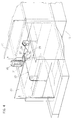
- Figure 5 shows a variant of the apparatus indicated by 100. Some parts of the apparatus 100 are similar to those of the apparatus 10; they have the same numbers but increased by 100 and will not be described in detail.
- the apparatus 100 thus comprises a washing/rinsing chamber 114 and a drying/disinfection chamber 116, adjacent to each other and communicating through an opening 115.
- the chamber 114 communicates with the outside through a loading opening with a door (not shown) that can be opened manually, for introduction of the racks 22.
- the chamber 116 communicates with the outside through an opening 117.
- the openings 115 and 117 are closed tight by means of raisable doors in a plurality of sections, indicated as a whole by 120 and 130 respectively.
- a bottom section of each of these, 121, 131 respectively, is joined to a raising chain, 123, 133 respectively, each operated by a motor 128, so that they wind and unwind simultaneously; raising of each bottom section therefore causes successive raising of the other sections, which thus remain grouped in the appropriate space at the top of the machine.
- Unwinding of the cables 123, 133 allows the sections to be lowered by gravity until they are positioned to form a seal between each other and against the surfaces 120' and 130' of the apparatus (which are generally the surfaces that define the lower water collection tanks).
- the transfer system for the racks 22, indicated by the bands 143 and 147, is substantially similar to that of the preceding apparatus.
- the water supply system illustrated here as two rotary sprayers, an upper one 151 and a lower one 152, is also of the traditional type.
- At least one lower germicidal lamp 154 is provided, mounted so that it can move longitudinally and/or transversally, with any known system: In this case also computer control is foreseen.
- the computer On opening the front loading door, after the machine has completed the loading cycles and the parameters (temperatures) have been reached, the computer gives its consent for the operations.
- the rack sensor When the rack is inserted into the washing chamber, the rack sensor enables the washing chamber for operation.
- doors 120, 130 When the loading door is closed, if doors 120, 130 are open, they close and a door closure sensor initiates the washing program (the times of which can be set on the control computer). On completion of the washing time, rinsing is carried out, for a time that can be set. Once rinsing is finished, a fume exhaustion fan comes into operation and frees the chamber of all steam.
- a sensor sends the computer the signal to close the doors and start the drying and germicidal ray cycle.
- the lamps After a certain drying time, which eliminates the vast majority of the residual water, the lamps come into operation and carry out their germicidal action for predetermined times, stopping when drying is completed.
- the washing chamber is free and can be used for washing another rack, irrespective of whether the drying area is in operation or not.
- the computer takes care of interfacing of the two chambers and waits until both have finished the cycle before transferring the rack being washed to the drying chamber and the one being dried to the external resting table.
Applications Claiming Priority (2)
| Application Number | Priority Date | Filing Date | Title |
|---|---|---|---|
| ITMI932348 | 1993-11-04 | ||
| IT93MI002348A IT1266676B1 (it) | 1993-11-04 | 1993-11-04 | Apparecchio per lavaggio-asciugatura di vasellame,a due camere, compatto |
Publications (1)
| Publication Number | Publication Date |
|---|---|
| EP0651967A1 true EP0651967A1 (fr) | 1995-05-10 |
Family
ID=11367150
Family Applications (1)
| Application Number | Title | Priority Date | Filing Date |
|---|---|---|---|
| EP94117003A Withdrawn EP0651967A1 (fr) | 1993-11-04 | 1994-10-27 | Procédé et appareil compact à deux chambres pour laver et sécher la vaisselle |
Country Status (2)
| Country | Link |
|---|---|
| EP (1) | EP0651967A1 (fr) |
| IT (1) | IT1266676B1 (fr) |
Cited By (2)
| Publication number | Priority date | Publication date | Assignee | Title |
|---|---|---|---|---|
| CN101869462A (zh) * | 2010-05-24 | 2010-10-27 | 官刚强 | 全自动餐饮具洗涤消毒机 |
| DE102015207169A1 (de) * | 2015-04-21 | 2016-10-27 | Meiko Maschinenbau Gmbh & Co. Kg | Trocknungseinrichtung für Geschirrspülmaschinen |
Citations (5)
| Publication number | Priority date | Publication date | Assignee | Title |
|---|---|---|---|---|
| DE7800591U1 (de) * | 1977-02-03 | 1978-10-19 | Zanussi Grandi Impianti S.P.A., Pordenone (Italien) | Geschirrwaschmaschine fuer gewerbliche verwendung |
| DD152717A1 (de) * | 1980-09-03 | 1981-12-09 | Hanna Wegner | Vorrichtung zum trocknen von bestecken |
| EP0048519A1 (fr) * | 1980-09-24 | 1982-03-31 | Unilever N.V. | Appareil et procédé pour nettoyer mécaniquement la vaisselle |
| DE3337369A1 (de) * | 1983-10-14 | 1985-04-25 | Jakobus Janhsen | Geschirrspuelmaschine |
| EP0512691A1 (fr) * | 1991-05-10 | 1992-11-11 | British Gas plc | Appareil de séchage |
-
1993
- 1993-11-04 IT IT93MI002348A patent/IT1266676B1/it active IP Right Grant
-
1994
- 1994-10-27 EP EP94117003A patent/EP0651967A1/fr not_active Withdrawn
Patent Citations (5)
| Publication number | Priority date | Publication date | Assignee | Title |
|---|---|---|---|---|
| DE7800591U1 (de) * | 1977-02-03 | 1978-10-19 | Zanussi Grandi Impianti S.P.A., Pordenone (Italien) | Geschirrwaschmaschine fuer gewerbliche verwendung |
| DD152717A1 (de) * | 1980-09-03 | 1981-12-09 | Hanna Wegner | Vorrichtung zum trocknen von bestecken |
| EP0048519A1 (fr) * | 1980-09-24 | 1982-03-31 | Unilever N.V. | Appareil et procédé pour nettoyer mécaniquement la vaisselle |
| DE3337369A1 (de) * | 1983-10-14 | 1985-04-25 | Jakobus Janhsen | Geschirrspuelmaschine |
| EP0512691A1 (fr) * | 1991-05-10 | 1992-11-11 | British Gas plc | Appareil de séchage |
Cited By (3)
| Publication number | Priority date | Publication date | Assignee | Title |
|---|---|---|---|---|
| CN101869462A (zh) * | 2010-05-24 | 2010-10-27 | 官刚强 | 全自动餐饮具洗涤消毒机 |
| DE102015207169A1 (de) * | 2015-04-21 | 2016-10-27 | Meiko Maschinenbau Gmbh & Co. Kg | Trocknungseinrichtung für Geschirrspülmaschinen |
| DE102015207169B4 (de) * | 2015-04-21 | 2020-08-20 | Meiko Maschinenbau Gmbh & Co. Kg | Trocknungseinrichtung für Geschirrspülmaschinen |
Also Published As
| Publication number | Publication date |
|---|---|
| ITMI932348A0 (it) | 1993-11-04 |
| ITMI932348A1 (it) | 1995-05-04 |
| IT1266676B1 (it) | 1997-01-09 |
Similar Documents
| Publication | Publication Date | Title |
|---|---|---|
| JP3298014B2 (ja) | 工業用洗浄設備 | |
| WO2020096176A1 (fr) | Séchoir de lavage et de stérilisation des chaussures | |
| EP3009201A1 (fr) | Appareil de lavage, en particulier pour désinfection à la chaleur | |
| CN109998365A (zh) | 一种炒菜机器人及其智能炒菜控制系统 | |
| US3221754A (en) | Dishwashing machines | |
| CN105266173A (zh) | 干果的生产工艺及其生产线 | |
| WO2002011602A2 (fr) | Mecanisme d'elevation/abaissement de charge | |
| EP0651967A1 (fr) | Procédé et appareil compact à deux chambres pour laver et sécher la vaisselle | |
| US5599398A (en) | Process and machine for cleaning parts | |
| EP0615114B1 (fr) | Système de pesage | |
| CN216925051U (zh) | 一种生产食品罐用的高温消毒烘干机 | |
| KR102305150B1 (ko) | 양말 살균장치 | |
| EP3636823B1 (fr) | Appareil de traitement de tissu | |
| EP0227275B1 (fr) | Appareil de traitement d'objets usinés | |
| CN113651038B (zh) | 一种全自动医疗传输装置及其运行方法 | |
| US5396835A (en) | Apparatus for raising and baking bakery goods | |
| CN110037323A (zh) | 一种农产品烤售一体机及自动出料机构 | |
| JPH0334581Y2 (fr) | ||
| JP2864233B2 (ja) | 容器洗浄装置 | |
| JP2000140780A (ja) | 殺菌機能付袋清浄装置 | |
| CN214882425U (zh) | 具有杀菌功能的洗涤装置 | |
| CN220149895U (zh) | 布巾清洗机构 | |
| CN219607630U (zh) | 一种袋装食品用的分级式烘干机 | |
| JPH0330433B2 (fr) | ||
| CN216533254U (zh) | 一种种蛋入孵输送线 |
Legal Events
| Date | Code | Title | Description |
|---|---|---|---|
| PUAI | Public reference made under article 153(3) epc to a published international application that has entered the european phase |
Free format text: ORIGINAL CODE: 0009012 |
|
| AK | Designated contracting states |
Kind code of ref document: A1 Designated state(s): AT BE CH DE DK ES FR GB IE LI LU NL PT SE |
|
| 17P | Request for examination filed |
Effective date: 19951030 |
|
| GRAG | Despatch of communication of intention to grant |
Free format text: ORIGINAL CODE: EPIDOS AGRA |
|
| 17Q | First examination report despatched |
Effective date: 19980629 |
|
| GRAG | Despatch of communication of intention to grant |
Free format text: ORIGINAL CODE: EPIDOS AGRA |
|
| GRAH | Despatch of communication of intention to grant a patent |
Free format text: ORIGINAL CODE: EPIDOS IGRA |
|
| STAA | Information on the status of an ep patent application or granted ep patent |
Free format text: STATUS: THE APPLICATION IS DEEMED TO BE WITHDRAWN |
|
| 18D | Application deemed to be withdrawn |
Effective date: 19990112 |