EP0651300B1 - Bilderzeugungsgerät - Google Patents
Bilderzeugungsgerät Download PDFInfo
- Publication number
- EP0651300B1 EP0651300B1 EP95100526A EP95100526A EP0651300B1 EP 0651300 B1 EP0651300 B1 EP 0651300B1 EP 95100526 A EP95100526 A EP 95100526A EP 95100526 A EP95100526 A EP 95100526A EP 0651300 B1 EP0651300 B1 EP 0651300B1
- Authority
- EP
- European Patent Office
- Prior art keywords
- cartridge
- shaft
- drum
- image
- transfer
- Prior art date
- Legal status (The legal status is an assumption and is not a legal conclusion. Google has not performed a legal analysis and makes no representation as to the accuracy of the status listed.)
- Expired - Lifetime
Links
Images


Classifications
-
- G—PHYSICS
- G03—PHOTOGRAPHY; CINEMATOGRAPHY; ANALOGOUS TECHNIQUES USING WAVES OTHER THAN OPTICAL WAVES; ELECTROGRAPHY; HOLOGRAPHY
- G03G—ELECTROGRAPHY; ELECTROPHOTOGRAPHY; MAGNETOGRAPHY
- G03G21/00—Arrangements not provided for by groups G03G13/00 - G03G19/00, e.g. cleaning, elimination of residual charge
- G03G21/16—Mechanical means for facilitating the maintenance of the apparatus, e.g. modular arrangements
- G03G21/18—Mechanical means for facilitating the maintenance of the apparatus, e.g. modular arrangements using a processing cartridge, whereby the process cartridge comprises at least two image processing means in a single unit
- G03G21/1839—Means for handling the process cartridge in the apparatus body
- G03G21/1842—Means for handling the process cartridge in the apparatus body for guiding and mounting the process cartridge, positioning, alignment, locks
- G03G21/1853—Means for handling the process cartridge in the apparatus body for guiding and mounting the process cartridge, positioning, alignment, locks the process cartridge being mounted perpendicular to the axis of the photosensitive member
-
- G—PHYSICS
- G03—PHOTOGRAPHY; CINEMATOGRAPHY; ANALOGOUS TECHNIQUES USING WAVES OTHER THAN OPTICAL WAVES; ELECTROGRAPHY; HOLOGRAPHY
- G03G—ELECTROGRAPHY; ELECTROPHOTOGRAPHY; MAGNETOGRAPHY
- G03G15/00—Apparatus for electrographic processes using a charge pattern
- G03G15/01—Apparatus for electrographic processes using a charge pattern for producing multicoloured copies
- G03G15/0105—Details of unit
- G03G15/0131—Details of unit for transferring a pattern to a second base
-
- G—PHYSICS
- G03—PHOTOGRAPHY; CINEMATOGRAPHY; ANALOGOUS TECHNIQUES USING WAVES OTHER THAN OPTICAL WAVES; ELECTROGRAPHY; HOLOGRAPHY
- G03G—ELECTROGRAPHY; ELECTROPHOTOGRAPHY; MAGNETOGRAPHY
- G03G15/00—Apparatus for electrographic processes using a charge pattern
- G03G15/14—Apparatus for electrographic processes using a charge pattern for transferring a pattern to a second base
- G03G15/16—Apparatus for electrographic processes using a charge pattern for transferring a pattern to a second base of a toner pattern, e.g. a powder pattern, e.g. magnetic transfer
- G03G15/1605—Apparatus for electrographic processes using a charge pattern for transferring a pattern to a second base of a toner pattern, e.g. a powder pattern, e.g. magnetic transfer using at least one intermediate support
- G03G15/1615—Apparatus for electrographic processes using a charge pattern for transferring a pattern to a second base of a toner pattern, e.g. a powder pattern, e.g. magnetic transfer using at least one intermediate support relating to the driving mechanism for the intermediate support, e.g. gears, couplings, belt tensioning
-
- G—PHYSICS
- G03—PHOTOGRAPHY; CINEMATOGRAPHY; ANALOGOUS TECHNIQUES USING WAVES OTHER THAN OPTICAL WAVES; ELECTROGRAPHY; HOLOGRAPHY
- G03G—ELECTROGRAPHY; ELECTROPHOTOGRAPHY; MAGNETOGRAPHY
- G03G15/00—Apparatus for electrographic processes using a charge pattern
- G03G15/14—Apparatus for electrographic processes using a charge pattern for transferring a pattern to a second base
- G03G15/16—Apparatus for electrographic processes using a charge pattern for transferring a pattern to a second base of a toner pattern, e.g. a powder pattern, e.g. magnetic transfer
- G03G15/1665—Apparatus for electrographic processes using a charge pattern for transferring a pattern to a second base of a toner pattern, e.g. a powder pattern, e.g. magnetic transfer by introducing the second base in the nip formed by the recording member and at least one transfer member, e.g. in combination with bias or heat
- G03G15/167—Apparatus for electrographic processes using a charge pattern for transferring a pattern to a second base of a toner pattern, e.g. a powder pattern, e.g. magnetic transfer by introducing the second base in the nip formed by the recording member and at least one transfer member, e.g. in combination with bias or heat at least one of the recording member or the transfer member being rotatable during the transfer
-
- G—PHYSICS
- G03—PHOTOGRAPHY; CINEMATOGRAPHY; ANALOGOUS TECHNIQUES USING WAVES OTHER THAN OPTICAL WAVES; ELECTROGRAPHY; HOLOGRAPHY
- G03G—ELECTROGRAPHY; ELECTROPHOTOGRAPHY; MAGNETOGRAPHY
- G03G21/00—Arrangements not provided for by groups G03G13/00 - G03G19/00, e.g. cleaning, elimination of residual charge
- G03G21/16—Mechanical means for facilitating the maintenance of the apparatus, e.g. modular arrangements
- G03G21/1642—Mechanical means for facilitating the maintenance of the apparatus, e.g. modular arrangements for connecting the different parts of the apparatus
- G03G21/1647—Mechanical connection means
-
- G—PHYSICS
- G03—PHOTOGRAPHY; CINEMATOGRAPHY; ANALOGOUS TECHNIQUES USING WAVES OTHER THAN OPTICAL WAVES; ELECTROGRAPHY; HOLOGRAPHY
- G03G—ELECTROGRAPHY; ELECTROPHOTOGRAPHY; MAGNETOGRAPHY
- G03G21/00—Arrangements not provided for by groups G03G13/00 - G03G19/00, e.g. cleaning, elimination of residual charge
- G03G21/16—Mechanical means for facilitating the maintenance of the apparatus, e.g. modular arrangements
- G03G21/1661—Mechanical means for facilitating the maintenance of the apparatus, e.g. modular arrangements means for handling parts of the apparatus in the apparatus
- G03G21/168—Mechanical means for facilitating the maintenance of the apparatus, e.g. modular arrangements means for handling parts of the apparatus in the apparatus for the transfer unit
-
- G—PHYSICS
- G03—PHOTOGRAPHY; CINEMATOGRAPHY; ANALOGOUS TECHNIQUES USING WAVES OTHER THAN OPTICAL WAVES; ELECTROGRAPHY; HOLOGRAPHY
- G03G—ELECTROGRAPHY; ELECTROPHOTOGRAPHY; MAGNETOGRAPHY
- G03G21/00—Arrangements not provided for by groups G03G13/00 - G03G19/00, e.g. cleaning, elimination of residual charge
- G03G21/16—Mechanical means for facilitating the maintenance of the apparatus, e.g. modular arrangements
- G03G21/18—Mechanical means for facilitating the maintenance of the apparatus, e.g. modular arrangements using a processing cartridge, whereby the process cartridge comprises at least two image processing means in a single unit
- G03G21/1839—Means for handling the process cartridge in the apparatus body
- G03G21/1857—Means for handling the process cartridge in the apparatus body for transmitting mechanical drive power to the process cartridge, drive mechanisms, gears, couplings, braking mechanisms
- G03G21/1864—Means for handling the process cartridge in the apparatus body for transmitting mechanical drive power to the process cartridge, drive mechanisms, gears, couplings, braking mechanisms associated with a positioning function
-
- G—PHYSICS
- G03—PHOTOGRAPHY; CINEMATOGRAPHY; ANALOGOUS TECHNIQUES USING WAVES OTHER THAN OPTICAL WAVES; ELECTROGRAPHY; HOLOGRAPHY
- G03G—ELECTROGRAPHY; ELECTROPHOTOGRAPHY; MAGNETOGRAPHY
- G03G2215/00—Apparatus for electrophotographic processes
- G03G2215/01—Apparatus for electrophotographic processes for producing multicoloured copies
- G03G2215/0167—Apparatus for electrophotographic processes for producing multicoloured copies single electrographic recording member
- G03G2215/0174—Apparatus for electrophotographic processes for producing multicoloured copies single electrographic recording member plural rotations of recording member to produce multicoloured copy
- G03G2215/018—Linearly moving set of developing units, one at a time adjacent the recording member
-
- G—PHYSICS
- G03—PHOTOGRAPHY; CINEMATOGRAPHY; ANALOGOUS TECHNIQUES USING WAVES OTHER THAN OPTICAL WAVES; ELECTROGRAPHY; HOLOGRAPHY
- G03G—ELECTROGRAPHY; ELECTROPHOTOGRAPHY; MAGNETOGRAPHY
- G03G2221/00—Processes not provided for by group G03G2215/00, e.g. cleaning or residual charge elimination
- G03G2221/16—Mechanical means for facilitating the maintenance of the apparatus, e.g. modular arrangements and complete machine concepts
- G03G2221/1603—Mechanical means for facilitating the maintenance of the apparatus, e.g. modular arrangements and complete machine concepts for multicoloured copies
-
- G—PHYSICS
- G03—PHOTOGRAPHY; CINEMATOGRAPHY; ANALOGOUS TECHNIQUES USING WAVES OTHER THAN OPTICAL WAVES; ELECTROGRAPHY; HOLOGRAPHY
- G03G—ELECTROGRAPHY; ELECTROPHOTOGRAPHY; MAGNETOGRAPHY
- G03G2221/00—Processes not provided for by group G03G2215/00, e.g. cleaning or residual charge elimination
- G03G2221/16—Mechanical means for facilitating the maintenance of the apparatus, e.g. modular arrangements and complete machine concepts
- G03G2221/1642—Mechanical means for facilitating the maintenance of the apparatus, e.g. modular arrangements and complete machine concepts for the transfer unit
-
- G—PHYSICS
- G03—PHOTOGRAPHY; CINEMATOGRAPHY; ANALOGOUS TECHNIQUES USING WAVES OTHER THAN OPTICAL WAVES; ELECTROGRAPHY; HOLOGRAPHY
- G03G—ELECTROGRAPHY; ELECTROPHOTOGRAPHY; MAGNETOGRAPHY
- G03G2221/00—Processes not provided for by group G03G2215/00, e.g. cleaning or residual charge elimination
- G03G2221/16—Mechanical means for facilitating the maintenance of the apparatus, e.g. modular arrangements and complete machine concepts
- G03G2221/1651—Mechanical means for facilitating the maintenance of the apparatus, e.g. modular arrangements and complete machine concepts for connecting the different parts
- G03G2221/1654—Locks and means for positioning or alignment
-
- G—PHYSICS
- G03—PHOTOGRAPHY; CINEMATOGRAPHY; ANALOGOUS TECHNIQUES USING WAVES OTHER THAN OPTICAL WAVES; ELECTROGRAPHY; HOLOGRAPHY
- G03G—ELECTROGRAPHY; ELECTROPHOTOGRAPHY; MAGNETOGRAPHY
- G03G2221/00—Processes not provided for by group G03G2215/00, e.g. cleaning or residual charge elimination
- G03G2221/16—Mechanical means for facilitating the maintenance of the apparatus, e.g. modular arrangements and complete machine concepts
- G03G2221/1651—Mechanical means for facilitating the maintenance of the apparatus, e.g. modular arrangements and complete machine concepts for connecting the different parts
- G03G2221/1657—Mechanical means for facilitating the maintenance of the apparatus, e.g. modular arrangements and complete machine concepts for connecting the different parts transmitting mechanical drive power
-
- G—PHYSICS
- G03—PHOTOGRAPHY; CINEMATOGRAPHY; ANALOGOUS TECHNIQUES USING WAVES OTHER THAN OPTICAL WAVES; ELECTROGRAPHY; HOLOGRAPHY
- G03G—ELECTROGRAPHY; ELECTROPHOTOGRAPHY; MAGNETOGRAPHY
- G03G2221/00—Processes not provided for by group G03G2215/00, e.g. cleaning or residual charge elimination
- G03G2221/16—Mechanical means for facilitating the maintenance of the apparatus, e.g. modular arrangements and complete machine concepts
- G03G2221/18—Cartridge systems
- G03G2221/183—Process cartridge
Definitions
- the cartridge includes both a charging mechanism for charging the drum and a cleaning mechanism for cleaning it.
- An access opening is provided for imagewise exposure of a charged surface of the drum to create an electrostatic image on the drum.
- the electrostatic image is toned through another access opening in the cartridge by one of two toning stations which are rotatable into position opposite the access opening to create a toner image.
- the toner image is transferred to a receiving sheet fed through a receiving sheet opening into contact with the drum.
- the receiving sheet is separated from the drum by a special mechanism which is part of the cartridge and fed outside of the cartridge to a fusing device.
- An access opening to the drum permits transfer of toner images to a receiving sheet fed into engagement with the drum.
- Rotation of the drum is accomplished by a driving connection at the end of the cartridge which must mate with a drive member in the receiving apparatus. Projections are provided on the cartridge to prevent damage to the cartridge driving connection member from careless handling.
- an image forming apparatus which includes a replaceable cartridge supporting an image member.
- the cartridge includes an access opening for transfer of toner images from the image member to a transfer surface.
- the image forming apparatus includes a transfer member not part of the cartridge and having a transfer surface associated with it for receiving toner images from the image member.
- the cartridge is urged toward the transfer member to urge the image member into transfer engagement with the transfer surface.
- Control structure associated with the transfer member engages the cartridge to accurately position the image member with respect to the transfer member.
- the image member is drum-shaped, having a cylindrical outer image surface upon which toner images are formed as the image member rotates about an axis of rotation.
- the transfer member is a transfer drum also having an axis of rotation and a cylindrical outer surface.
- the image forming apparatus includes means for controlling the relative positions of the axes of rotation of the transfer member and the image member to maintain them parallel. Maintenance of parallelism between the axes of rotation of the image member and transfer member prevents image degradation during transfer.
- Fig. 1 is a perspective schematic of an image forming apparatus with housing and other support parts eliminated for clarity of illustration.
- Fig. 2 is a perspective view illustrating the drive train of an image forming apparatus with some parts in phantom and other parts eliminated for clarity of illustration.
- Fig. 3 is a front schematic of the image forming apparatus shown in Fig. 1 with portions of an image member cartridge shown in cross section for clarity of illustration.
- Fig. 4 is a front schematic of the drive train and cartridge portions of the image forming apparatus with portions eliminated and broken away for clarity of illustration.
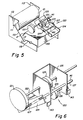
- Fig. 5 is a perspective view of a cartridge and a mounting structure portion of an alternative image forming apparatus.
- Fig. 6 is a perspective view of an over-center spring mechanism forming a part of the apparatus shown in Fig. 5.
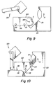
- Figs. 7 and 8 are front views of the structure shown in Fig. 5 in its partially loaded and fully loaded conditions, respectively.
- Figs. 9 and 10 are rear views of the structure shown in Figs. 7 and 8 also in its partially loaded and fully loaded conditions, respectively.
- Figs. 11 and 12 are top views of the structure shown in Figs. 5-10 in its partially loaded and fully loaded conditions, respectively.
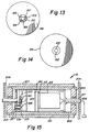
- Figs. 13 and 14 are front and rear views, respectively, of a circular disk which forms part of a knob 121 shown in Figs. 5 and 6.
- Fig. 15 is a top section of a transfer drum illustrating an alternative drive mechanism for the apparatus shown in Fig. 1.
- Printer 1 includes an image member, for example, a photoconductive drum 2 which is rotatable through a series of stations for forming a series of toner images of different colors.
- Photoconductive drum 2 has a cylindrical image surface which is first charged by a charging station 4 and then imagewise exposed by a laser 5 to create a series of electrostatic images.
- the electrostatic images are toned by toners of different color by a movable development device 6 which includes 3 or 4 separate development units. Each unit applies a different color toner to one of the series of electrostatic images to create a series of different color toner images on the cylindrical image surface of drum 2.
- the series of different color toner images are transferred in registration to a transfer surface associated with a transfer drum 10 to create a multicolor color image on that surface.
- a transfer surface associated with a transfer drum 10 As shown in Fig. 1, the surface to which the toner images are transferred is a cylindrical peripheral surface of drum 10 itself. However, the toner images could also be transferred to a receiving sheet held on the surface of drum 10 as is well known in the art.
- the multicolor image is transferred by a transfer station 21 to a receiving sheet fed from a receiving sheet supply 45.
- the receiving sheet is then transported to a fuser 23 where the multicolor image is fixed and then to an output hopper 44 through an inverting path.
- the transfer surface of the transfer drum 10 is cleaned by an articulating cleaner 30 so that it may receive a new set of images.
- the photoconductive drum 2 is cleaned continuously during image formation by a cleaning device 12.
- the photoconductive drum 2 is supplied to the printer 1 in a cartridge 3 which cartridge may also contain other portions of printer 1.
- the cartridge may contain the charging device 4, the developing device 6 and/or cleaning devices 30 and 12.
- a cartridge housing contains image member 2, an opening for exposure by laser 5, charging device 4 and image member cleaning device 12. It also includes a sump 11 for receiving toner cleaned by cleaning device 12 off image member 2 and a sump 35 for receiving toner cleaned off transfer drum 10 by transfer drum cleaner 30.
- the housing also includes an opening 7 providing access to image member 2 for development device 6 and an opening 9 providing access to image member 2 for transfer drum 10.
- Articulating cleaner 30 is moved in and out of engagement with transfer drum 10 by a solenoid 31. It includes a cleaning roller which rolls on the surface of transfer drum 10 which roller is biased and formed of a material which encourages removal of toner to the roller. Cleaned toner is scraped off the roller by a scraping blade 32. An opening 36 in the cartridge housing receives scraped toner into sump 35.
- a receiving sheet is fed from a receiving sheet supply 20 into transfer relation with transfer drum 10.
- transfer is accomplished by a corona transfer station 21, known in the art.
- the transfer sheet is picked off transfer drum 10 by a movable pick-off 22 which also directs the transfer sheet to fuser 23.
- FIG. 2 is a perspective drawing illustrating the drive train from motor 42 through transfer drum 10 and photoconductive drum 2.
- engagement as used herein with reference to the image member and the transfer member is preferably direct contacting engagement of those members. However, although not preferred, it can also be engagement through a receiving sheet carried by the transfer member.
- transfer drum 10 is shown with an external drive engagement between transfer drum 10 and motor 42, motor 42 could be positioned inside transfer drum 10 and internally engaged with drum 10 to save space in printer 1. This latter embodiment is shown in Fig. 15.
- transfer drum 10 includes an outer layer 201 of polyurethane cast or otherwise formed on an aluminum or steel base 202.
- Layer 201 defines a cylindrical transfer surface 207 to which several single color toner images are transferred directly to form a multicolor image.
- a pair of gudgeons 203 and 204 support base 202 and are journaled for rotation about fixed shafts 205 and 206.
- Shafts 205 and 206 rotate about different portions of a single axis of rotation and are considered a single shaft for all purposes herein.
- Shafts 205 and 206 are fixed in mechanism plates 208 and 209 of the printer, and support an internal drive housing 210 located inside transfer drum 10.
- Internal drive housing 210 includes a motor 212 and planetary gear box 213.
- the planetary gear box provides a suitable gear reduction between the motor and an output shaft 221.
- a drive gear 222 is fixed on output shaft 221 and is rotated by output shaft 221 to drive a first idler gear 225.
- First idler gear 225 is fixed to an idler shaft 226 journaled for rotation with respect to drive housing 210.
- a second idler gear 227 is also fixed to and is rotated by idler shaft 226.
- Second idler gear 227 engages an internal gear 230 fixed to the inside of drum base 202 to rotate drum 10 with respect to shafts 205 and 206 and housing 210.
- the structure shown in Fig. 15 is particularly useful to drive a transfer drum 10 which receives toner images directly to its surface and then transfers them to a receiving sheet, because such a drum does not require a vacuum source or other structure for holding a receiving sheet to the drum surface, thereby leaving the room necessary for the transfer drum drive housing 210. It is also particularly useful with a cartridge loading image member 2 as shown in Figs. 2-5 which image member is driven by transfer drum 10, since, with such a structure, no usable space is taken up in printer 1 for a drive for either of drums 10 or 2.
- cartridge 3 is shown supported by receiving mechanism 50 which positions the cartridge so that sufficient engagement between drum 2 and drum 10 is obtained to both transfer images and drive drum 2.
- receiving mechanism 50 which positions the cartridge so that sufficient engagement between drum 2 and drum 10 is obtained to both transfer images and drive drum 2.
- Fig. 3 construction is feasible for modest image quality.
- tolerances in the manufacture of cartridge 3 receiving structure 50 and the location of drum 10 become confining. Accordingly, more precise positioning mechanisms are shown in Figs.4-14.
- cartridge 3 includes drum 2, charging station 4 and cleaning device 12, but does not include a sump for receiving toner cleaned from drum 10.
- Transfer drum 10 is supported on a shaft 51 which, in turn, is supported by a pair of mechanism plates of the apparatus, for example, mechanism plates 208 and 209, shown in Fig. 15.
- Also supported on shaft 51 are a pair of triangularly shaped plates 52 at opposite ends of drum 10. Plates 52 are also connected by an auxiliary shaft 54 and are generally rotatable about an axis 53 by a shaft 51 but rigidly fixed with respect to each other.
- Photoconductive drum 2 is supported for rotation about an axis 56 by a shaft 57 which shaft extends beyond the end walls of cartridge 3.
- Drum 2 rotates with respect to shaft 57, so shaft 57 is fixed with respect to cartridge 3.
- a slot 55 in each of triangular plates 52 is shaped to receive snugly the ends of shaft 57.
- plates 52 can be rotated to a position slightly counterclockwise from that shown in Fig. 4 to receive shaft 57 into slots 55. Plates 52, transfer drum 10 and cartridge 3 are then rotated clockwise around shaft 51 until plates 52 rest on a stop 62 which is a permanent portion of printer 1. The cartridge 3 can still be rotated about shaft 57 until a portion of cartridge 3 rests on another stop 61 which is also a permanent part of printer 1.
- Stops 61 and 62 generally orient the cartridge in printer 1 for access to the exposing and developing devices 5 and 6 (Figs. 1 and 3).
- the nip between drums 10 and 2 is controlled by a spring 65 which urges cartridge 3 toward transfer drum 10 and the image surface of drum 2 into engagement with the transfer surface associated with drum 10.
- a spring 67 may also be used to maintain the contact between cartridge 3 and stop 61, thereby preventing rotation of the cartridge around shaft 57. Spring 67 may not in fact be necessary, since the rotation of transfer drum 10 will also urge cartridge 3 against stop 61.
- spring 67 can be part of an upper part of printer 1 which, after the insertion of cartridge 3 is closed onto a lower part, which lower part holds motor 42, transfer drum 10, laser 5, development device 6 and associated support structure.
- Spring 65 although part of the lower portion of the apparatus, can also be tensioned and/or applied to cartridge 3 as part of this closing operation.
- Transfer drum 10 is supported on a shaft 111, which, in turn, is supported by front and rear guide plates 112 and 113, respectively.
- Shaft 111 may be in two sections as are shafts 205 and 206 shown in Fig. 15.
- Guide plates 112 and 113 extend substantially to the right from transfer drum 10 and each include control surfaces 115 and support surfaces 116 which cooperate with portions of cartridge 103.
- an over-center spring mechanism 120 is actuated to drive cartridge 103 from an unloaded condition shown in Figs. 7 and 9 to a fully loaded condition shown in Figs. 8 and 10.
- Cartridge 103 is positioned in the apparatus by the operator resting left and right rear support bosses 131 and 132, respectively, on rear support surface 116 as shown in Fig. 9, a single front support boss 133 on front guide surface 116, with all three support bosses thus resting on support surfaces 116.
- Support surfaces 116 are generally horizontal.
- Drum 2 is mounted in cartridge 103 on a support shaft 105 (which also may be in two sections as shown in Fig. 15), and rotates about an axis at the center of the shaft.
- Over-center spring 120 is actuated (as described below) to push cartridge 103 to the left as shown in Fig. 8. This action pushes shaft 105 into contact with control surfaces 115 of guide plates 112 and 113. Control surfaces 115 are parallel with each other. Their projection is generally tangent to transfer drum shaft 111. As seen in Figs. 8 and 10, over-center spring 120 pushes cartridge 103 until shaft 105 rides up control surfaces 115 until drum 2 engages transfer drum 10. A notch 119 in guide plates 112 and 113 causes cartridge 103 to no longer be supported by bosses 131 and 133.
- cartridge 103 is supported only by the ends of shaft 105 riding up parallel control surfaces 115 and by boss 132 resting on support surface 116.
- This three-point contact forces shaft 105 to always contact both control surfaces 115.
- the peripheral surfaces of drums 2 and 10 are cylindrical and accurately mounted on shafts 105 and 111, and the location of control surfaces 115 are accurate, the axes of drums 2 and 10 will be parallel.
- a roller 160 is shown in Figs. 11 and 12, and is part of a structure to prevent movement of cartridge 103 to the rear.
- a complementary roller or spring to the front of the path of cartridge 103 is not shown.
- Cartridge 103 can be pushed to the left (as seen in Fig. 8) by any appropriate spring mechanism.
- Figs. 6, 11 and 12 illustrate an over-center spring mechanism 120 which is particularly useful for this function.
- lever 124 is generally urged by springs 127 toward either a latched condition shown in Figs. 6, 8, 10 and 12 or toward an unlatched condition shown in Figs. 5, 7, 9 and 11.
- knob 121 is turned in either direction until protrusion 154 engages one of groove ends 156 or 157. From that point on, rotation of knob 121 rotates shaft 122 until the "over-center" condition of springs 127 occurs. At this point, the spring accelerates the rotation of lever 124 in either a latching or unlatching direction causing the shaft 122 to rotate ahead of either groove end 156 or 157 until lever 124 reaches its fully latched or unlatched condition.
- This design has the advantage of fully positioning the lever 124 without the spring acceleration of lever 124 or its stopping being felt by the person rotating knob 121. It also discourages over rotation of lever 124 by the operator which can damage cartridge 103 or drums 2 or 10.
- the positioning device shown in Figs. 5-14 positions the photoconductive drum 2 against the transfer drum 10 with the axes of revolution of the two drums parallel. Precision is required in only the manufacture and assembly of shafts 111 and 105, drums 2 and 10 and guide surfaces 115. This parallelism is important to prevent image degradation in high-quality transfer. This makes it particularly usable in a multicolor printer providing high-quality multicolor images which are the results of superimposing a series of single color images. It is particularly usable when the photoconductive drum is driven by the transfer drum (as shown in Figs. 1-4) because such driving engagement between the two drums requires a substantial nip which increases the degradation of the image if the axes are not parallel. However, it certainly can be used in structures in which the photoconductive drum 2 is driven by its own drive means and either drives the transfer drum or is driven independently of it.
- Shaft 105 is preferably a stationary shaft with photoconductive drum 2 mounted for rotation with respect to it. This eliminates the necessity of making guide surfaces 115 bearing surfaces. Shaft 111 can rotate with transfer drum 10 or be stationary, with transfer drum 10 rotating with respect to it as shown in Fig. 15.
- Shaft 105 could be rotatable with photoconductive drum 2. In such a design, it would be preferable to have shaft 105 supported for rotation in bearings, which bearings have a housing which contacts guide surfaces 115. Alternatively, if surfaces 115 are made of self-lubricating material, shaft 105 can rotate with drum 2 on surfaces 115.
- each of the positioning structures shown herein has particular adaptability and is designed for a transfer drum 10 which receives toner images directly on its outer transfer surface
- the structures can also be used with a transfer drum which supports a receiving sheet on its outer surface.
Claims (5)
- Bilderzeugungsvorrichtung miteiner austauschbaren Fotoleiterkassette (3) mit einem Gehäuse und einem trommelförmigen Bildträger (2) sowie mit einer Welle (57; 105), die den Bildträger um eine Achse (56) drehbar lagert und mit einander gegenüberliegenden Enden versehen ist, die sich über einander gegenüberliegende Enden des Bildträgers (2) hinaus erstrecken und von der Außenseite des Kassettengehäuses zugänglich sind, wobei der Bildträger (2) eine Bildempfangsfläche aufweist, auf der Tonerbilder erzeugbar sind,einer Übertragungstrommel (10), die eine Drehachse (53) und eine zylindrische äußere Übertragungsfläche zum Aufnehmen von Tonerbildern von der Bildempfangsfläche aufweist, undeinem Mittel (52; 115), das bezüglich der Drehachse (53) der übertragungstrommel (10) befestigt ist, um die Position der den Bildträger lagernden Welle (57; 105) derart zu steuern, daß die Achse (56) des Bildträgers parallel zur Drehachse (53) der Übertragungstrommel (10) ausgerichtet bleibt.
- Bilderzeugungsvorrichtung nach Anspruch 1, dadurch gekennzeichnet, daß die Welle (57; 105) bezüglich der Kassette (3) befestigt ist, der Bildträger (2) drehbar um die Welle (57; 105) gelagert ist und die Welle (57; 105) einander gegenüberliegende Enden aufweist, die sich zur Kassettenaußenseite hin erstrecken und mit dem Steuermittel (52; 115) in Eingriff bringbar sind.
- Bilderzeugungsvorrichtung nach Anspruch 1 oder 2, dadurch gekennzeichnet, daß ein Mittel (65, 67; 120) vorgesehen ist, das die Kassette zur Übertragungstrommel hin drückt, um die Bildempfangsfläche mit der Übertragungsfläche in Eingriff zu bringen.
- Bilderzeugungsvorrichtung nach Anspruch 3, dadurch gekennzeichnet, daß das Steuermittel (52; 115) mindestens zwei Steuerflächen (115) umfaßt, von denen eine jeweils mit dem gegenüberliegenden Ende der Welle (57; 105) in Eingriff bringbar ist, daß die Steuerflächen (55; 115) sich von ihren Eingriffsstellungen mit den Enden der Welle (57; 105) zur Übertragungstrommel (10) hin erstrekken und das Druckmittel (65, 67; 120) eine Vorrichtung aufweist, das die Kassette in eine Richtung drückt, in der die Enden der Welle mit den Steuerflächen in Berührung bleiben, während die Bildempfangsfläche in Eingriff mit der Übertragungsfläche bringbar ist.
- Bilderzeugungsvorrichtung nach Anspruch 1 bis 4, dadurch gekennzeichnet, daß die Übertragungstrommel (10) auf einer Welle (51; 111) mit einander gegenüberliegenden Enden gelagert ist und daß die Enden bezüglich des Steuermittels (52; 115) befestigt sind.
Applications Claiming Priority (7)
| Application Number | Priority Date | Filing Date | Title |
|---|---|---|---|
| US65025991A | 1991-02-04 | 1991-02-04 | |
| US07/650,260 US5087939A (en) | 1991-02-04 | 1991-02-04 | Image forming apparatus and image member cartridge |
| US650260 | 1991-02-04 | ||
| US07/650,325 US5138372A (en) | 1991-02-04 | 1991-02-04 | Image forming apparatus and an image member cartridge |
| US650259 | 1991-02-04 | ||
| EP92912927A EP0523235B1 (de) | 1991-02-04 | 1992-02-03 | Bilderzeugungsgerät und arbeitseinheit mit einem bildträgerelement |
| US650325 | 1996-05-20 |
Related Parent Applications (1)
| Application Number | Title | Priority Date | Filing Date |
|---|---|---|---|
| EP92912927.8 Division | 1992-02-03 |
Publications (3)
| Publication Number | Publication Date |
|---|---|
| EP0651300A2 EP0651300A2 (de) | 1995-05-03 |
| EP0651300A3 EP0651300A3 (de) | 1995-09-20 |
| EP0651300B1 true EP0651300B1 (de) | 1997-06-18 |
Family
ID=27417841
Family Applications (2)
| Application Number | Title | Priority Date | Filing Date |
|---|---|---|---|
| EP95100526A Expired - Lifetime EP0651300B1 (de) | 1991-02-04 | 1992-02-03 | Bilderzeugungsgerät |
| EP92912927A Expired - Lifetime EP0523235B1 (de) | 1991-02-04 | 1992-02-03 | Bilderzeugungsgerät und arbeitseinheit mit einem bildträgerelement |
Family Applications After (1)
| Application Number | Title | Priority Date | Filing Date |
|---|---|---|---|
| EP92912927A Expired - Lifetime EP0523235B1 (de) | 1991-02-04 | 1992-02-03 | Bilderzeugungsgerät und arbeitseinheit mit einem bildträgerelement |
Country Status (4)
| Country | Link |
|---|---|
| EP (2) | EP0651300B1 (de) |
| JP (1) | JPH06501574A (de) |
| DE (2) | DE69220510T2 (de) |
| WO (1) | WO1992015049A2 (de) |
Families Citing this family (1)
| Publication number | Priority date | Publication date | Assignee | Title |
|---|---|---|---|---|
| JP2012203308A (ja) * | 2011-03-28 | 2012-10-22 | Fuji Xerox Co Ltd | 画像形成装置、転写装置 |
Family Cites Families (10)
| Publication number | Priority date | Publication date | Assignee | Title |
|---|---|---|---|---|
| JPS5788461A (en) * | 1980-11-22 | 1982-06-02 | Canon Inc | Picture formation device |
| JPS58105268A (ja) * | 1981-12-18 | 1983-06-23 | Fuji Xerox Co Ltd | 電子写真複写機の転写装置 |
| JPS5997167A (ja) * | 1982-11-26 | 1984-06-04 | Konishiroku Photo Ind Co Ltd | 静電記録装置 |
| JPS59220756A (ja) * | 1983-05-30 | 1984-12-12 | Konishiroku Photo Ind Co Ltd | 記録装置 |
| US4723145A (en) * | 1985-03-22 | 1988-02-02 | Canon Kabushiki Kaisha | Color image forming apparatus comprising separate motors for driving the image bearing member and the transfer material supporting member |
| US4712906A (en) * | 1987-01-27 | 1987-12-15 | Eastman Kodak Company | Electrostatographic apparatus having a transfer drum |
| NL8702691A (nl) * | 1987-11-11 | 1989-06-01 | Oce Nederland Bv | Inrichting voor het overdragen van een poederbeeld naar een ontvangstmateriaal en het fixeren van het poederbeeld daarop. |
| JP2686267B2 (ja) * | 1988-01-30 | 1997-12-08 | キヤノン株式会社 | 画像形成装置 |
| EP0376617B1 (de) * | 1988-12-27 | 1994-03-02 | Konica Corporation | Farbbilderzeugungsgerät |
| US5070370A (en) * | 1990-12-24 | 1991-12-03 | Eastman Kodak Company | Image-forming apparatus having a replaceable cartridge and a transfer member cleaning device |
-
1992
- 1992-02-03 EP EP95100526A patent/EP0651300B1/de not_active Expired - Lifetime
- 1992-02-03 DE DE1992620510 patent/DE69220510T2/de not_active Expired - Fee Related
- 1992-02-03 DE DE69203807T patent/DE69203807T2/de not_active Expired - Fee Related
- 1992-02-03 EP EP92912927A patent/EP0523235B1/de not_active Expired - Lifetime
- 1992-02-03 JP JP4511583A patent/JPH06501574A/ja active Pending
- 1992-02-03 WO PCT/US1992/000675 patent/WO1992015049A2/en active IP Right Grant
Also Published As
| Publication number | Publication date |
|---|---|
| WO1992015049A3 (en) | 1993-01-21 |
| EP0523235A1 (de) | 1993-01-20 |
| DE69220510T2 (de) | 1997-12-04 |
| WO1992015049A2 (en) | 1992-09-03 |
| EP0523235B1 (de) | 1995-08-02 |
| DE69203807D1 (de) | 1995-09-07 |
| DE69220510D1 (de) | 1997-07-24 |
| EP0651300A3 (de) | 1995-09-20 |
| JPH06501574A (ja) | 1994-02-17 |
| DE69203807T2 (de) | 1996-03-21 |
| EP0651300A2 (de) | 1995-05-03 |
Similar Documents
| Publication | Publication Date | Title |
|---|---|---|
| US7349649B2 (en) | Process cartridge, positioning mechanism therefor and electrophotographic image forming apparatus | |
| US8565639B2 (en) | Process cartridge and image forming apparatus | |
| US6865361B2 (en) | Transfer belt unit and image forming apparatus using the same | |
| US7092657B2 (en) | Electrophotographic image forming apparatus, and process cartridge | |
| US5138372A (en) | Image forming apparatus and an image member cartridge | |
| US5087939A (en) | Image forming apparatus and image member cartridge | |
| US6829453B2 (en) | Carrying apparatus and image forming apparatus including same in which the relative positioning of carrying rollers is automatically adjusted | |
| US4841330A (en) | Recording apparatus | |
| EP0651300B1 (de) | Bilderzeugungsgerät | |
| US5138374A (en) | Image forming apparatus including means for receiving an image member cartridge | |
| JPH10186851A (ja) | 画像形成装置 | |
| JP2001042636A (ja) | 軸受け部材及び現像剤担持体ユニット及び現像装置及びプロセスカートリッジ及び電子写真画像形成装置 | |
| JP3036144B2 (ja) | 電子写真装置 | |
| JP3714376B2 (ja) | 画像形成装置 | |
| JPH04147274A (ja) | 画像形成装置のプロセスカートリッジ | |
| JP2789040B2 (ja) | カラー画像形成装置 | |
| JP3140535B2 (ja) | 画像形成装置 | |
| JP2006292869A (ja) | プロセスカートリッジ | |
| JP3246563B2 (ja) | 画像形成装置 | |
| JP2003149912A (ja) | 転写ベルトユニットおよびそれを用いた画像形成装置 | |
| JP2662528B2 (ja) | 現像装置 | |
| JP2003167412A (ja) | 画像形成装置 | |
| JP2945052B2 (ja) | 画像形成装置 | |
| JP2003167431A (ja) | 現像装置及びそれを用いた画像形成装置 | |
| JP2003167430A (ja) | 画像形成装置 |
Legal Events
| Date | Code | Title | Description |
|---|---|---|---|
| PUAI | Public reference made under article 153(3) epc to a published international application that has entered the european phase |
Free format text: ORIGINAL CODE: 0009012 |
|
| AC | Divisional application: reference to earlier application |
Ref document number: 523235 Country of ref document: EP |
|
| AK | Designated contracting states |
Kind code of ref document: A2 Designated state(s): DE FR GB NL |
|
| PUAL | Search report despatched |
Free format text: ORIGINAL CODE: 0009013 |
|
| AK | Designated contracting states |
Kind code of ref document: A3 Designated state(s): DE FR GB NL |
|
| 17P | Request for examination filed |
Effective date: 19960222 |
|
| GRAG | Despatch of communication of intention to grant |
Free format text: ORIGINAL CODE: EPIDOS AGRA |
|
| GRAH | Despatch of communication of intention to grant a patent |
Free format text: ORIGINAL CODE: EPIDOS IGRA |
|
| 17Q | First examination report despatched |
Effective date: 19961108 |
|
| GRAH | Despatch of communication of intention to grant a patent |
Free format text: ORIGINAL CODE: EPIDOS IGRA |
|
| GRAA | (expected) grant |
Free format text: ORIGINAL CODE: 0009210 |
|
| AC | Divisional application: reference to earlier application |
Ref document number: 523235 Country of ref document: EP |
|
| AK | Designated contracting states |
Kind code of ref document: B1 Designated state(s): DE FR GB NL |
|
| REF | Corresponds to: |
Ref document number: 69220510 Country of ref document: DE Date of ref document: 19970724 |
|
| ET | Fr: translation filed | ||
| PLBE | No opposition filed within time limit |
Free format text: ORIGINAL CODE: 0009261 |
|
| STAA | Information on the status of an ep patent application or granted ep patent |
Free format text: STATUS: NO OPPOSITION FILED WITHIN TIME LIMIT |
|
| 26N | No opposition filed | ||
| REG | Reference to a national code |
Ref country code: GB Ref legal event code: 732E |
|
| NLS | Nl: assignments of ep-patents |
Owner name: NEXPRESS SOLUTIONS LLC |
|
| REG | Reference to a national code |
Ref country code: GB Ref legal event code: IF02 |
|
| PGFP | Annual fee paid to national office [announced via postgrant information from national office to epo] |
Ref country code: DE Payment date: 20040227 Year of fee payment: 13 |
|
| REG | Reference to a national code |
Ref country code: GB Ref legal event code: 732E |
|
| PGFP | Annual fee paid to national office [announced via postgrant information from national office to epo] |
Ref country code: NL Payment date: 20050110 Year of fee payment: 14 |
|
| PGFP | Annual fee paid to national office [announced via postgrant information from national office to epo] |
Ref country code: FR Payment date: 20050202 Year of fee payment: 14 |
|
| PG25 | Lapsed in a contracting state [announced via postgrant information from national office to epo] |
Ref country code: DE Free format text: LAPSE BECAUSE OF NON-PAYMENT OF DUE FEES Effective date: 20050901 |
|
| PG25 | Lapsed in a contracting state [announced via postgrant information from national office to epo] |
Ref country code: NL Free format text: LAPSE BECAUSE OF NON-PAYMENT OF DUE FEES Effective date: 20060901 |
|
| NLV4 | Nl: lapsed or anulled due to non-payment of the annual fee |
Effective date: 20060901 |
|
| PGFP | Annual fee paid to national office [announced via postgrant information from national office to epo] |
Ref country code: GB Payment date: 20070105 Year of fee payment: 16 |
|
| REG | Reference to a national code |
Ref country code: FR Ref legal event code: ST Effective date: 20061031 |
|
| PG25 | Lapsed in a contracting state [announced via postgrant information from national office to epo] |
Ref country code: FR Free format text: LAPSE BECAUSE OF NON-PAYMENT OF DUE FEES Effective date: 20060228 |
|
| GBPC | Gb: european patent ceased through non-payment of renewal fee |
Effective date: 20080203 |
|
| PG25 | Lapsed in a contracting state [announced via postgrant information from national office to epo] |
Ref country code: GB Free format text: LAPSE BECAUSE OF NON-PAYMENT OF DUE FEES Effective date: 20080203 |