EP0650781B1 - Antriebseinrichtung für einen mehrachsigen Transport von Werkstücken in einer Transferpresse - Google Patents
Antriebseinrichtung für einen mehrachsigen Transport von Werkstücken in einer Transferpresse Download PDFInfo
- Publication number
- EP0650781B1 EP0650781B1 EP94115059A EP94115059A EP0650781B1 EP 0650781 B1 EP0650781 B1 EP 0650781B1 EP 94115059 A EP94115059 A EP 94115059A EP 94115059 A EP94115059 A EP 94115059A EP 0650781 B1 EP0650781 B1 EP 0650781B1
- Authority
- EP
- European Patent Office
- Prior art keywords
- hoisting
- arrangement according
- drive
- movement
- pillars
- Prior art date
- Legal status (The legal status is an assumption and is not a legal conclusion. Google has not performed a legal analysis and makes no representation as to the accuracy of the status listed.)
- Expired - Lifetime
Links
- 238000012546 transfer Methods 0.000 title claims description 7
- 230000033001 locomotion Effects 0.000 claims description 57
- 230000007246 mechanism Effects 0.000 claims description 28
- 238000006073 displacement reaction Methods 0.000 claims description 5
- 238000005259 measurement Methods 0.000 claims description 2
- 238000000034 method Methods 0.000 description 8
- 230000008569 process Effects 0.000 description 8
- 230000008901 benefit Effects 0.000 description 3
- 238000013461 design Methods 0.000 description 3
- 230000008878 coupling Effects 0.000 description 2
- 238000010168 coupling process Methods 0.000 description 2
- 238000005859 coupling reaction Methods 0.000 description 2
- 238000011161 development Methods 0.000 description 2
- 230000018109 developmental process Effects 0.000 description 2
- 230000001360 synchronised effect Effects 0.000 description 2
- 230000006978 adaptation Effects 0.000 description 1
- 230000015572 biosynthetic process Effects 0.000 description 1
- 238000010276 construction Methods 0.000 description 1
- 238000005516 engineering process Methods 0.000 description 1
- 238000003754 machining Methods 0.000 description 1
- 238000004519 manufacturing process Methods 0.000 description 1
- 239000002184 metal Substances 0.000 description 1
- 239000013641 positive control Substances 0.000 description 1
- 238000009420 retrofitting Methods 0.000 description 1
Images

Classifications
-
- B—PERFORMING OPERATIONS; TRANSPORTING
- B21—MECHANICAL METAL-WORKING WITHOUT ESSENTIALLY REMOVING MATERIAL; PUNCHING METAL
- B21D—WORKING OR PROCESSING OF SHEET METAL OR METAL TUBES, RODS OR PROFILES WITHOUT ESSENTIALLY REMOVING MATERIAL; PUNCHING METAL
- B21D43/00—Feeding, positioning or storing devices combined with, or arranged in, or specially adapted for use in connection with, apparatus for working or processing sheet metal, metal tubes or metal profiles; Associations therewith of cutting devices
- B21D43/02—Advancing work in relation to the stroke of the die or tool
- B21D43/04—Advancing work in relation to the stroke of the die or tool by means in mechanical engagement with the work
- B21D43/05—Advancing work in relation to the stroke of the die or tool by means in mechanical engagement with the work specially adapted for multi-stage presses
- B21D43/055—Devices comprising a pair of longitudinally and laterally movable parallel transfer bars
Definitions
- the invention relates to a drive device for a Multi-axis transport of workpieces in one Transfer press according to the preamble of claim 1.
- a transfer or step press is one Single press with a certain number of one after the other switched tool stations, d. H. the operations are summarized in a single press.
- the workpieces are processed in successive operations, d. H. during a press stroke, several find at the same time Operations instead.
- the transport of the workpieces from stage to Level takes place via a two-dimensional or three-dimensional gripper system, which is usually included the tappet drive is mechanically coupled. For that be two gripper rails arranged parallel to each other - also Carrier rails called, over the entire length of the step press passed on both sides to the workpieces within the Press to move.
- the gripper rail In general, the gripper rail must be carried out after this three-dimensional movement back to the starting position to be led back.
- the Special workpiece gripper systems For gripping the workpieces, the Special workpiece gripper systems.
- the invention has for its object a Drive device for multi-axis transport of To create workpieces in such a transfer press that especially space-saving and with little construction effort is trained.
- it is said to be very compact Building a combined lifting and closing movement of the Gripper rails are created.
- This task is based on a drive device according to the preamble of claim 1 by the characterizing features of claim 1 solved.
- the drive device has known systems the advantage that a very compact structure for a combined lifting and closing movement of the Gripper rails is created.
- the gripper rails are for Execution of the movement sequence on so-called lifting columns stored, which in turn by one for both gripper rails common vertical drive via a height adjustable Crossbeam and via an actuator for one
- the position of the transverse displacement is adjustable. You can the lifting and closing movements in their movements largely independent due to separate motor drive be designed.
- the mechanical Coupling and arrangement of the movement systems an immediate Influencing the movements to each other, d. H. to shorten cycle times there are also overlaps in motion possible.
- the arrangement of the lifting column in one is particularly advantageous own housing, which is a relative movement between Lifting column and housing and thus an independent movement when Lifts and closes.
- the lifting column housing to carry out the closing movement in Traverse in the transverse direction, so the lifting column can at the same time be moved vertically within the lifting column housing.
- the adjustability of the gripper rails for carrying out the transverse closing movement can be more advantageous Formation of the invention by separately driven Threaded spindles with opposite pitch or through a Belt drive or the like. Each time the lifting column housing with appropriate drive means Mistake. With a passage of the threaded spindles the lifting columns becomes a symmetrical one at the same time Force attack guaranteed.
- the Lifting process via a mechanical lever linkage which by a linear movement by means of a separate servo motor or the like is driven and a lifting movement of associated crossbar causes.
- a lever linkage can be arranged compactly in an associated housing the lifting movement of those connected to the lifting columns Carry out cross-beam or cantilever.
- the crossbeam serves at the same time Horizontal positioning of the cross-adjustable lifting columns.
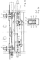
- a step press 1 shows the two through the entire length the gripper rails 2, 3 and a lifting mechanism 4 for performing the lifting movement and an opening or closing mechanism 5 for performing the closing movement of the gripper rails 2, 3.
- the basic representation of the triaxial transport in DE 38 42 182 C1 lists each gripper rail 2, 3 each closing process a transverse movement about a central axis 6, 7 through to the transverse closing movement each perform.
- the center symmetry plane 8 shifts consequently in the transverse direction to position 8 ', i.e. H. the Gripper rail 2, 3 performs a transverse movement during the Clamping or closing process through.
- the opening and opening responsible for the transverse movement Locking device 5 (hereinafter "locking device” is therefore both for the movement between the Middle symmetry planes 8, 8 'during the Workpiece transport process as well as for setting the Setup axis responsible.
- the innermost position of the Gripper rails 2, 3 are designated 2 ', 3'.
- the in the Figures 1 to 3 illustrated embodiments of the invention show the lifting mechanism 4 and the closing mechanism 5 to carry out the up and down movement and the sideways closing movement of the two Gripper rails 2, 3.
- the longitudinal movement of the gripper rails 2, 3 by means of an advancement mechanism is shown in FIGS to 3 not shown. It can be done in an analogous manner be made as this is DE 38 42 182 C1 Applicant shows. Similarly, a separate one Drive according to the introductory DE 33 29 900 C2 for the advance mechanism be present.
- the synchronous lifting and closing movement of the two Gripper rails 2, 3 take place via a lifting column 9, which in its upper area with a slide guide 10 the gripper rail 2, 3 is connected.
- a lifting column 9 of the two gripper rails 2, 3 At the bottom is each lifting column 9 of the two gripper rails 2, 3 on one common crossbar 11 over a respective Guide carriage 12 in one with respect to Longitudinal press axis transverse guide 13 mounted.
- the Guides 13 cover a travel length that the required scope for width adjustment of the setup axis including closing path.
- the crossbar 11 is designed as a U-shaped component in cross section, with an upper, transverse surface section 14 for receiving the guide 13 thereon and two laterally downwardly extending legs 15, 15 ', on which at a distance l 1 two opposite bearing webs 16, 16 'and 17, 17' are welded on.
- 2b shows a section AA through the right bearing webs 16, 16 'shown in FIG. 1a.
- each angle lever 19 in one fixed bearing 21 stored, with an approximately horizontally aligned lower leg 22 over a Bearing point 23 with the lower part of the respective bearing webs 16, 16 'or 17, 17' is connected.
- An upward one approximately vertical further leg 24 of each angle lever 19, 20 is about a bearing point 25 with an approximately horizontally aligned push rod 26 connected.
- the Push rod 26 is on its right, shown in Fig. 1a Drive side via a tab 27 with the individual joints 28, 29 connected to a guide head 30 which in a Bearing shoe 31 mounted on the housing 18 in a longitudinal guide 32 is.
- the guide head 30 has a spindle nut 33 on the side in which a horizontally aligned spindle 34 a Spindle drive 35 engages.
- the spindle drive 35 is as adjustable electric motor or hydraulic motor and flanged to the side of the housing 18. It can also be a other linear drive for a linear adjustment of the Guide head 30 may be provided. He has one Wegmeß coupled 74 on the adjustment movement of the Spindle nut 33 and thus the stroke movement is detected.
- the opening or closing movement of the two gripper rails 2, 3 happens via the further, separate opening and Locking mechanism 5, consisting of a separate Drive motor 48, which may be designed as a gear motor and its drive shaft as threaded spindles 49, 49 ' over the entire length of the press lock box extends.
- a separate Drive motor 48 which may be designed as a gear motor and its drive shaft as threaded spindles 49, 49 ' over the entire length of the press lock box extends.
- the drive shafts 49, 49 ' are mounted in a bearing 51, and from there sit down in one piece as a shaft section 49 '.
- the drive shafts 49, 49 ' consist of Threaded spindles with opposite pitch.
- a path measuring device 73 is provided, which Transverse displacement of the gripper rails 2, 3 detected and the required measurement signals to the positioning motor 48 forwards.
- the bearing housing 46 arranged on both sides for the lifting columns 9 each have a spindle nut 52 which are in engagement with the drive shafts 49, 49 '. That the Drive motor 48 opposite end of the drive shaft 49 is stored in a bearing housing 53. Because of a reverse slope of the drive shaft 49, 49 'move the two spindle nuts 52 when the Drive shaft (arrow 54) in the opposite direction, see above that the bearing housing 46 connected to the spindle nuts 52 and thus the lifting columns 9 and with them the gripper rails 2, 3 are moved towards or away from each other. For this purpose, the upper cover plates 55 are against each other designed to be slidable.
- the drive shaft 49 is passed through a longitudinal slot 56 with the height h 1 . Since the drive shaft 49 remains in the same horizontal plane, the longitudinal slot must be provided with a certain height h 1 in order to permit the necessary lifting movement of the lifting column 9.
- 1a also shows inner stops 57 and outer stops Stops 58, the lateral travel movement or Transverse movement during the clamping or closing process limit and with the side wall of the bearing housing 46 work together.
- Fig. 1a shows the position of the lever linkage 42 such that the lower stroke position of the two gripper rails 2, 3 is reached, d. H. the drive shaft 49 is in the upper area of the longitudinal slot 56.
- the lifting movement by means of the lifting mechanism 4 and the Opening or closing movement by means of the closing mechanism 5 can be run independently and overlapping in time.
- the locking mechanism 5 serves both for implementation the closing movement during the machining process as well to adapt to the required part width at Retrofitting.
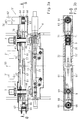
- Fig. 3a, 3b shows one modified opening or closing mechanism 5 '.
- Lift mechanism 4 corresponds to the embodiment of the Figures 1 and 2.
- the 3a in front view and Fig. 3b is a top view of a belt drive 60 provided consists of a circumferential belt 61.
- a separate drive motor 62 Travel sensor 73 'is provided, on the drive shaft 63 of which first deflection roller 64 is arranged.
- the one over the pulley 64 guided toothed belt 61 is on the opposite Side of the press over a second guide roller 65, the is mounted on a bearing block 66.
- the bearing block 66 itself is via clamping screws 67 on a housing 68 for the Locking mechanism held.
- the axes of rotation of the two Deflection rollers 64, 65 are vertical and are parallel the central axes of the two lifting columns 9.
- the bearing housing 46 is for the respective Lifting column 9 between the two belt halves 61, 61 ', 3b, the left bearing housing 46 with the upper belt 61 via a non-positive or positive connection 69 is connected, while the in Fig. 3a shown right bearing housing 46 with the lower Belt 61 'over a corresponding non-positive or positive Connection is connected.
- the latter is due to the Sectional drawings not shown in detail.
- Fig. 3b shows the section B-B in Fig. 3a to the vertical center plane of symmetry 50. From there goes the section as shown in the right part of the Fig. 3b upwards in the guide area of the right Bearing housing 46.
- Carriage 70 provided four in its four corner areas has profiled rollers 71 with two opposite guide rods 72, 72 'engaged stand. These guide rods 72, 72 'extend over the total distance required to complete the required transverse movements of the two gripper rails 2, 3rd
Landscapes
- Engineering & Computer Science (AREA)
- Mechanical Engineering (AREA)
- Press Drives And Press Lines (AREA)
Description
- Greifen der Werkstücke mittels einer Querbewegung der Greiferschiene;
- Heben des Werkstücks mittels einer Vertikalbewegung der Greiferschiene;
- Weitertransport des Werkstücks mittels einer Längsbewegung der Greiferschiene;
- Absenken der Werkstücke;
- Öffnen der Greifer;
- Rücklauf in Ausgangsstellung.
- Fig. 1a, Fig. 1b
- ein erstes Ausführungsbeispiel für eine Antriebseinrichtung der Greiferschienen mit einem Spindelantrieb in unterer Hubstellung nach Fig. 1a und oberer Hubstellung nach Fig. 1b,
- Fig. 2a
- eine Draufsicht auf die Hubverstelleinrichtung mit Hebelgestänge nach Fig. 1a, 1b entlang der Schnittlinie A-A in Fig. 1a,
- Fig. 2b
- einen Schnitt durch das Hebelgestänge nach Fig. 1b entlang der Schnittlinie C-C,
- Fig. 3a
- eine alternative Ausführungsform für den Antrieb des Schließmechanismus mittels eines Riemenantriebs und
- Fig. 3b
- eine Draufsicht des Riemenantriebs nach Fig. 3a entlang der Schnittlinie B-B.
Claims (14)
- Antriebseinrichtung für einen mehrachsigen Transport von Werkstücken durch nacheinander folgende Bearbeitungsstationen einer Umformpresse, und insbesondere einer Transferpresse, wobei zwei parallel zueinander angeordnete Greiferschienen vorgesehen sind, die mittels eines Hubmechanismus in Vertikalrichtung sowie mittels eines Öffnungs- bzw. Schließmechanismus in Querrichtung bewegbar sind, wobei zur Durchführung der vertikalen Hubbewegung (45) unterhalb der Greiferschienen (2, 3) eine mittels eines antreibbaren Hebelgestänges (42) auf- und abwärts bewegbare Quertraverse (11) vorgesehen ist und die Quertraverse (11) Führungsmittel (13) für hierauf verschiebbare Hubsäulen (9) aufweist, mittels welchen jeweils eine Greiferschiene (2, 3) quer verschiebbar gelagert ist, wobei zur Durchführung einer quergerichteten Öffnungs- bzw. Schließbewegung der Greiferschienen (2, 3) den gegenüberliegenden Hubsäulen (9) für die Greiferschienen (2, 3) eine gemeinsame Antriebseinrichtung (49, 61) zugeordnet ist, dadurch gekennzeichnet, daß die mit den Hubsäulen (9) verbundene Quertraverse (11) als nach unten hin offenes U-Profil ausgebildet ist, welches sich weitestgehend über die gesamte Breite des Schließkastens der Presse erstreckt und dessen oberer Flächenabschnitt (14) die Führungsmittel (13) für einen Führungsschlitten (12) an den Hubsäulen (9) aufweist.
- Einrichtung nach Anspruch 1, dadurch gekennzeichnet, daß jede Hubsäule (9) in einem Lagergehäuse (46) angeordnet ist und daß das Lagergehäuse Befestigungsmittel (52, 69) für einen Quertransport mittels einer Linear-Antriebseinrichtung (49, 61) aufweist.
- Einrichtung nach Anspruch 1 oder 2, dadurch gekennzeichnet, daß die Linear-Antriebseinrichtung für die Hubsäulen (9) bzw. dessen Lagergehäuse (46) durch eine, die Hubsäulen (9) vorzugsweise durchsetzende Gewindespindel (49) gebildet ist, die mit einer zugehörigen Spindelmutter (52) am Lagergehäuse (46) in Eingriff steht.
- Einrichtung nach Anspruch 1 oder 2, dadurch gekennzeichnet, daß die Linear-Antriebseinrichtung für die Querverschiebung der Hubsäulen (9) durch einen umlaufenden Riemenantrieb (61) oder dergleichen gebildet ist, wobei die Hubsäulen (9) bzw. dessen Lagergehäuse an jeweils gegenüberliegenden Riemensträngen befestigt sind.
- Einrichtung nach Anspruch 4, dadurch gekennzeichnet, daß das Lagergehäuse (46) einen Schlitten (70) mit Führungsrollen (71) umfaßt, die sich an zugehörigen, ortsfesten Führungsstangen (72) abstützen.
- Einrichtung nach einem der vorhergehenden Ansprüche, dadurch gekennzeichnet, daß sich die Lagergehäuse (46) beidseitig an Anschlägen (57, 58) zur Wegbegrenzung abstützen.
- Einrichtung nach einem der vorhergehenden Ansprüche, dadurch gekennzeichnet, daß die mit den Hubsäulen (9) verbundene Quertraverse (11) mit ihrem nach unten hin offenen U-Profil seitliche Schenkel (15, 15') aufweist, an denen ein Hebelgestänge (42) für die Hubbewegung der Greiferschienen (2, 3) angreift.
- Einrichtung nach Anspruch 7, dadurch gekennzeichnet, daß das U-Profil der Quertraverse (11) in einem nach oben hin offenen, ebenfalls U-förmigen Gehäuse (18) eingebettet und über im Gehäuse (18) gelagerte Winkelhebel (19, 20) und Lagerstegen (16, 17) in diesem aufund abwärts bewegbar ist.
- Einrichtung nach Anspruch 8, dadurch gekennzeichnet, daß die Winkelhebel (19, 20) zur Durchführung der Vertikalbewegung der Quertraverse (11) über eine antreibbare, und insbesondere horizontal verschiebbare Schubstange (26) bewegbar bzw. verschwenkbar sind.
- Einrichtung nach Anspruch 9, dadurch gekennzeichnet, daß der Antrieb für die Schubstange (26) über einen Elektro-, Servomotor (35) bzw. Positioniermotor oder dergleichen mit Gewindespindel (34) und Spindelmutter (33) oder einem gleichwirkenden Hydromotor oder Linearantrieb erfolgt.
- Einrichtung nach einem der vorhergehenden Ansprüche, dadurch gekennzeichnet, daß die Querverschiebung der mit den Greiferschienen (2, 3) verbundenen Hubsäulen (9) zur Durchführung der im Arbeitstakt erforderlichen Öffnungs- und Schließbewegung einerseits und zur Verstellung der Rüstachse bei geänderter Werkstückgröße andererseits erfolgt.
- Einrichtung nach einem der vorhergehenden Ansprüche, dadurch gekennzeichnet, daß der Hubmechanismus (4) und/oder der Öffnungs- und Schließmechanismus (5) jeweils einen gesonderten, vorzugsweise elektrischen Antrieb.
- Einrichtung nach einem der vorhergehenden Ansprüche, dadurch gekennzeichnet, daß der Antrieb für den Hubmechanismus (4) und/oder für den Öffnungs- oder Schließmechanismus (5) und/oder einem Vorrückmechanismus für die Greiferschienen (2, 3) über einen gemeinsamen mechanischen Antrieb erfolgt.
- Einrichtung nach einem der vorhergehenden Ansprüche, dadurch gekennzeichnet, daß dem Hubmechanismus (4) und/oder dem Öffnungs- bzw. Schließmechanismus (5, 5') jeweils Wegmeßsysteme (74; 73, 73') zugeordnet sind.
Applications Claiming Priority (2)
| Application Number | Priority Date | Filing Date | Title |
|---|---|---|---|
| DE4336854A DE4336854A1 (de) | 1993-10-28 | 1993-10-28 | Antriebseinrichtung für einen mehrachsigen Transport von Werkstücken in einer Transferpresse |
| DE4336854 | 1993-10-28 |
Publications (3)
| Publication Number | Publication Date |
|---|---|
| EP0650781A2 EP0650781A2 (de) | 1995-05-03 |
| EP0650781A3 EP0650781A3 (de) | 1995-06-07 |
| EP0650781B1 true EP0650781B1 (de) | 1998-11-25 |
Family
ID=6501276
Family Applications (1)
| Application Number | Title | Priority Date | Filing Date |
|---|---|---|---|
| EP94115059A Expired - Lifetime EP0650781B1 (de) | 1993-10-28 | 1994-09-23 | Antriebseinrichtung für einen mehrachsigen Transport von Werkstücken in einer Transferpresse |
Country Status (3)
| Country | Link |
|---|---|
| EP (1) | EP0650781B1 (de) |
| DE (2) | DE4336854A1 (de) |
| ES (1) | ES2127322T3 (de) |
Cited By (1)
| Publication number | Priority date | Publication date | Assignee | Title |
|---|---|---|---|---|
| US6826944B1 (en) | 2000-05-12 | 2004-12-07 | Hermann Hagel | Transfer device and method for controlling a transfer device |
Families Citing this family (5)
| Publication number | Priority date | Publication date | Assignee | Title |
|---|---|---|---|---|
| DE19719097C2 (de) * | 1997-05-06 | 1999-06-17 | Erfurt Umformtechnik Gmbh | Verfahren zum Transport von Formteilen zwischen mehreren Stufen einer Transferpressenstraße, Umformanlage oder dergleichen |
| DE19914652C1 (de) * | 1999-03-31 | 2000-11-30 | Mueller Weingarten Maschf | Antriebssystem für die Schließbewegung eines mehrachsigen Transports von Werkstücken in einer Transferpresse |
| DE10128184B4 (de) * | 2001-06-11 | 2004-05-27 | Fraunhofer-Gesellschaft zur Förderung der angewandten Forschung e.V. | Vorrichtung zum mehrachsigen Transport von Werkstücken |
| DE102004005046B4 (de) | 2004-01-30 | 2008-01-24 | Müller Weingarten AG | Transportvorrichtung für Werkstücke in Pressen |
| DE102011118216B4 (de) | 2011-11-11 | 2013-09-19 | Schuler Pressen Gmbh | Antriebseinrichtung für einen mehrachsigen Transport von Werkstücken durch aufeinander folgende Bearbeitungsstationen einer Bearbeitungsmaschine |
Family Cites Families (7)
| Publication number | Priority date | Publication date | Assignee | Title |
|---|---|---|---|---|
| US4540087A (en) * | 1982-08-19 | 1985-09-10 | Kabushiki Kaisha Komatsu Seisakusho | Three-dimensional work transfer apparatus |
| DE3320830A1 (de) * | 1983-06-09 | 1984-12-13 | Hans 4320 Hattingen Schoen | Stufenvorschub fuer folgewerkzeuge, insbesondere an stanzpressen |
| US4614265A (en) * | 1985-07-22 | 1986-09-30 | Danly Machine Corporation | Apparatus for automatically splitting transfer feed rails in a transfer feed press |
| EP0224652B1 (de) * | 1985-09-09 | 1990-02-07 | Aida Engineering Ltd. | Fördervorrichtung für die Werkstücke bei einer Mehrstufenpresse |
| DD277853A1 (de) * | 1988-12-09 | 1990-04-18 | Warnke Umformtech Veb K | Verstellvorrichtung zur weiteneinstellung der greiferschienen einer transferpresse |
| DE3842182C1 (de) * | 1988-12-15 | 1989-09-28 | Maschinenfabrik Mueller-Weingarten Ag, 7987 Weingarten, De | |
| DD297085A5 (de) * | 1990-08-13 | 1992-01-02 | Umformtechnik Erfurt Gmbh,De | Werkstuecktransfereinrichtung |
-
1993
- 1993-10-28 DE DE4336854A patent/DE4336854A1/de not_active Withdrawn
-
1994
- 1994-09-23 ES ES94115059T patent/ES2127322T3/es not_active Expired - Lifetime
- 1994-09-23 EP EP94115059A patent/EP0650781B1/de not_active Expired - Lifetime
- 1994-09-23 DE DE59407335T patent/DE59407335D1/de not_active Expired - Lifetime
Cited By (1)
| Publication number | Priority date | Publication date | Assignee | Title |
|---|---|---|---|---|
| US6826944B1 (en) | 2000-05-12 | 2004-12-07 | Hermann Hagel | Transfer device and method for controlling a transfer device |
Also Published As
| Publication number | Publication date |
|---|---|
| ES2127322T3 (es) | 1999-04-16 |
| DE4336854A1 (de) | 1995-05-04 |
| EP0650781A2 (de) | 1995-05-03 |
| DE59407335D1 (de) | 1999-01-07 |
| EP0650781A3 (de) | 1995-06-07 |
Similar Documents
| Publication | Publication Date | Title |
|---|---|---|
| EP0850709B1 (de) | Transfereinrichtung und Mehrstationenpresse | |
| EP0671228B1 (de) | Transporteinrichtung für Werkstücke in einer Presse | |
| DE3784980T2 (de) | Kurzhubtransferpresse mit automatischer vorschubeinrichtung. | |
| EP0388610B2 (de) | Pressen-Anlage mit mehreren Pressen zum Bearbeiten von Blechteilen | |
| EP0672480A1 (de) | Transportsystem | |
| DE2417131A1 (de) | Pressenstrasse mit werkstuecktransportvorrichtung | |
| EP0930110B1 (de) | Transporteinrichtung | |
| DE3706160C2 (de) | ||
| DE19521976A1 (de) | Transportsystem | |
| DE4418417A1 (de) | Umsetzvorrichtung in einer Umformmaschine, insbesondere einer Transferpresse | |
| DE10328447B4 (de) | Transferpresse mit verbesserter Raumausnutzung | |
| EP0136598A2 (de) | Einrichtung zur Handhabung von Blechtafeln | |
| DE19654474A1 (de) | Flexibler Mehrachstransfer | |
| DE10122377C1 (de) | Vorrichtung zur Rückführung von Werkstücken | |
| EP0342257B1 (de) | Werkzeugmaschine mit Magazin und Werkzeugwechsler | |
| DE3539852A1 (de) | Mechanische schweisspresse | |
| EP0650781B1 (de) | Antriebseinrichtung für einen mehrachsigen Transport von Werkstücken in einer Transferpresse | |
| EP0857152B1 (de) | Verfahren und vorrichtung zum ausziehen von rollpaletten in der kompakt-lagertechnik, sowie rollpalette hierfür | |
| EP1000680B1 (de) | Modulare Transfereinrichtung mit Schwenk- und Linearantrieben | |
| DD258381B1 (de) | Dreidimensionale antriebseinheit fuer eingabe- und entnahmeeinrichtungen an pressen und transporteinrichtungen zwischen pressen, insbesondere fuer transfereinrichtungen in pressen | |
| EP0507098A1 (de) | Transporteinrichtung zum Transportieren von grossflächigen Teilen in einer Stufenpresse | |
| DE68908562T2 (de) | System zur übertragung von werkstücken durch eine reihe von arbeitsstationen. | |
| DE4320431B4 (de) | Transferpressenkomplex | |
| EP1512648B1 (de) | Vorrichtung zur Übergabe von Stückgut | |
| DE19506520A1 (de) | Transfervorrichtung |
Legal Events
| Date | Code | Title | Description |
|---|---|---|---|
| PUAI | Public reference made under article 153(3) epc to a published international application that has entered the european phase |
Free format text: ORIGINAL CODE: 0009012 |
|
| PUAL | Search report despatched |
Free format text: ORIGINAL CODE: 0009013 |
|
| AK | Designated contracting states |
Kind code of ref document: A2 Designated state(s): DE ES FR IT |
|
| AK | Designated contracting states |
Kind code of ref document: A3 Designated state(s): DE ES FR IT |
|
| 17P | Request for examination filed |
Effective date: 19950802 |
|
| 17Q | First examination report despatched |
Effective date: 19970228 |
|
| GRAG | Despatch of communication of intention to grant |
Free format text: ORIGINAL CODE: EPIDOS AGRA |
|
| RAP1 | Party data changed (applicant data changed or rights of an application transferred) |
Owner name: MUELLER WEINGARTEN AG |
|
| GRAG | Despatch of communication of intention to grant |
Free format text: ORIGINAL CODE: EPIDOS AGRA |
|
| GRAH | Despatch of communication of intention to grant a patent |
Free format text: ORIGINAL CODE: EPIDOS IGRA |
|
| GRAH | Despatch of communication of intention to grant a patent |
Free format text: ORIGINAL CODE: EPIDOS IGRA |
|
| GRAA | (expected) grant |
Free format text: ORIGINAL CODE: 0009210 |
|
| AK | Designated contracting states |
Kind code of ref document: B1 Designated state(s): DE ES FR IT |
|
| REF | Corresponds to: |
Ref document number: 59407335 Country of ref document: DE Date of ref document: 19990107 |
|
| ITF | It: translation for a ep patent filed | ||
| ET | Fr: translation filed | ||
| REG | Reference to a national code |
Ref country code: ES Ref legal event code: FG2A Ref document number: 2127322 Country of ref document: ES Kind code of ref document: T3 |
|
| PLBE | No opposition filed within time limit |
Free format text: ORIGINAL CODE: 0009261 |
|
| STAA | Information on the status of an ep patent application or granted ep patent |
Free format text: STATUS: NO OPPOSITION FILED WITHIN TIME LIMIT |
|
| 26N | No opposition filed | ||
| PGFP | Annual fee paid to national office [announced via postgrant information from national office to epo] |
Ref country code: FR Payment date: 20060922 Year of fee payment: 13 |
|
| REG | Reference to a national code |
Ref country code: FR Ref legal event code: ST Effective date: 20080531 |
|
| PG25 | Lapsed in a contracting state [announced via postgrant information from national office to epo] |
Ref country code: FR Free format text: LAPSE BECAUSE OF NON-PAYMENT OF DUE FEES Effective date: 20071001 |
|
| PGFP | Annual fee paid to national office [announced via postgrant information from national office to epo] |
Ref country code: IT Payment date: 20100924 Year of fee payment: 17 |
|
| PGFP | Annual fee paid to national office [announced via postgrant information from national office to epo] |
Ref country code: ES Payment date: 20110923 Year of fee payment: 18 Ref country code: DE Payment date: 20110815 Year of fee payment: 18 |
|
| PG25 | Lapsed in a contracting state [announced via postgrant information from national office to epo] |
Ref country code: DE Free format text: LAPSE BECAUSE OF NON-PAYMENT OF DUE FEES Effective date: 20130403 |
|
| PG25 | Lapsed in a contracting state [announced via postgrant information from national office to epo] |
Ref country code: IT Free format text: LAPSE BECAUSE OF NON-PAYMENT OF DUE FEES Effective date: 20120923 |
|
| REG | Reference to a national code |
Ref country code: DE Ref legal event code: R119 Ref document number: 59407335 Country of ref document: DE Effective date: 20130403 |
|
| REG | Reference to a national code |
Ref country code: ES Ref legal event code: FD2A Effective date: 20131018 |
|
| PG25 | Lapsed in a contracting state [announced via postgrant information from national office to epo] |
Ref country code: ES Free format text: LAPSE BECAUSE OF NON-PAYMENT OF DUE FEES Effective date: 20120924 |