EP0650765A2 - Anpassungsfähiges Farbspritzgerät - Google Patents
Anpassungsfähiges Farbspritzgerät Download PDFInfo
- Publication number
- EP0650765A2 EP0650765A2 EP94115293A EP94115293A EP0650765A2 EP 0650765 A2 EP0650765 A2 EP 0650765A2 EP 94115293 A EP94115293 A EP 94115293A EP 94115293 A EP94115293 A EP 94115293A EP 0650765 A2 EP0650765 A2 EP 0650765A2
- Authority
- EP
- European Patent Office
- Prior art keywords
- front body
- handle
- airbrush
- tubular cavity
- air
- Prior art date
- Legal status (The legal status is an assumption and is not a legal conclusion. Google has not performed a legal analysis and makes no representation as to the accuracy of the status listed.)
- Withdrawn
Links
- 238000004891 communication Methods 0.000 claims abstract description 5
- 239000003973 paint Substances 0.000 claims description 37
- 230000005484 gravity Effects 0.000 claims description 14
- 230000008878 coupling Effects 0.000 claims description 12
- 238000010168 coupling process Methods 0.000 claims description 12
- 238000005859 coupling reaction Methods 0.000 claims description 12
- 230000000694 effects Effects 0.000 description 2
- 238000010422 painting Methods 0.000 description 2
- 238000010276 construction Methods 0.000 description 1
- 230000000994 depressogenic effect Effects 0.000 description 1
- 238000012423 maintenance Methods 0.000 description 1
- 238000000034 method Methods 0.000 description 1
- 238000012986 modification Methods 0.000 description 1
- 230000004048 modification Effects 0.000 description 1
- 238000006467 substitution reaction Methods 0.000 description 1
Images
Classifications
-
- B—PERFORMING OPERATIONS; TRANSPORTING
- B05—SPRAYING OR ATOMISING IN GENERAL; APPLYING FLUENT MATERIALS TO SURFACES, IN GENERAL
- B05B—SPRAYING APPARATUS; ATOMISING APPARATUS; NOZZLES
- B05B7/00—Spraying apparatus for discharge of liquids or other fluent materials from two or more sources, e.g. of liquid and air, of powder and gas
- B05B7/24—Spraying apparatus for discharge of liquids or other fluent materials from two or more sources, e.g. of liquid and air, of powder and gas with means, e.g. a container, for supplying liquid or other fluent material to a discharge device
- B05B7/2402—Apparatus to be carried on or by a person, e.g. by hand; Apparatus comprising containers fixed to the discharge device
- B05B7/2478—Gun with a container which, in normal use, is located above the gun
-
- B—PERFORMING OPERATIONS; TRANSPORTING
- B05—SPRAYING OR ATOMISING IN GENERAL; APPLYING FLUENT MATERIALS TO SURFACES, IN GENERAL
- B05B—SPRAYING APPARATUS; ATOMISING APPARATUS; NOZZLES
- B05B7/00—Spraying apparatus for discharge of liquids or other fluent materials from two or more sources, e.g. of liquid and air, of powder and gas
- B05B7/24—Spraying apparatus for discharge of liquids or other fluent materials from two or more sources, e.g. of liquid and air, of powder and gas with means, e.g. a container, for supplying liquid or other fluent material to a discharge device
- B05B7/2402—Apparatus to be carried on or by a person, e.g. by hand; Apparatus comprising containers fixed to the discharge device
- B05B7/2405—Apparatus to be carried on or by a person, e.g. by hand; Apparatus comprising containers fixed to the discharge device using an atomising fluid as carrying fluid for feeding, e.g. by suction or pressure, a carried liquid from the container to the nozzle
- B05B7/2435—Apparatus to be carried on or by a person, e.g. by hand; Apparatus comprising containers fixed to the discharge device using an atomising fluid as carrying fluid for feeding, e.g. by suction or pressure, a carried liquid from the container to the nozzle the carried liquid and the main stream of atomising fluid being brought together by parallel conduits placed one inside the other
-
- B—PERFORMING OPERATIONS; TRANSPORTING
- B05—SPRAYING OR ATOMISING IN GENERAL; APPLYING FLUENT MATERIALS TO SURFACES, IN GENERAL
- B05B—SPRAYING APPARATUS; ATOMISING APPARATUS; NOZZLES
- B05B7/00—Spraying apparatus for discharge of liquids or other fluent materials from two or more sources, e.g. of liquid and air, of powder and gas
- B05B7/24—Spraying apparatus for discharge of liquids or other fluent materials from two or more sources, e.g. of liquid and air, of powder and gas with means, e.g. a container, for supplying liquid or other fluent material to a discharge device
- B05B7/2483—Spraying apparatus for discharge of liquids or other fluent materials from two or more sources, e.g. of liquid and air, of powder and gas with means, e.g. a container, for supplying liquid or other fluent material to a discharge device the supplying means involving no pressure or aspiration, e.g. means involving gravity or capillarity
Definitions
- the present invention concerns a novel airbrush which can be selectively gravity and siphon fed.
- Airbrushes have generally been available in two basic forms, gravity fed and siphon fed, Further, within these forms, a plethora of sizes of airbrushes are also available.
- a gravity fed airbrush generally has a receptacle or cup in which relatively small amounts of paint can be placed.
- the receptacle can generally be located anywhere above the point at which paint exits the airbrush and works by paint dripping into the airbrush.
- a siphon fed airbrush generally has a larger receptacle or paint jar attached below the paint exit point and generally has a tube connecting the paint jar with the airbrush. The passage of air over the end of the tube causes a negative pressure in the tube, which coupled with the positive pressure in the paint jar, causes the paint to be literally sucked, or siphoned, from the paint jar into the airbrush.
- Gravity fed and siphoning airbrushes are generally used for different tasks. If a paint job requires a great deal of paint, the user generally must use a siphon fed airbrush as it allows for more paint to be available. If greater painting precision is desired, the user will generally choose a gravity fed airbrush as the lighter weight paint receptacle and the availability of all of the air to push paint, rather than sucking paint, allows more precise movements and accuracy. As a result of these limited uses of each type of airbrush, the user must buy both types of airbrushes if he wishes to do large and small jobs. In addition, if the user has need of different sizes of airbrushes, he must then buy the different sizes in both gravity and siphoning types. The result is a large collection of different size and type airbrushes which must be prepared and then cleaned.
- an airbrush having a handle and a front body.
- the handle defines a first tubular cavity through which air may travel and the front body defines a second tubular cavity through which air may travel.
- the handle and front body also define a longitudinal axis.
- the front body is rotationally attached to the handle in such a way that the first tubular cavity is in communication with the second tubular cavity when the front body is rotated about the longitudinal axis of the airbrush with respect to the handle.
- the airbrush is further provided with a paint intake on the front body and a trigger and air intake on the handle.
- the paint intake can rotate from a siphoning position to a gravity feed position.
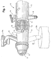
- FIG. 1 is a partial perspective view, partially cut away, of the airbrush of the present invention, showing both a gravity feed and a siphoning position.
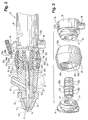
- FIG. 2 is an elevational view of the airbrush of FIG. 1 partially cut away to show a cross-sectional view of the front body of the airbrush.
- FIG. 3 is an exploded perspective view of the airbrush of the present invention showing the junction of the front body and the handle.
- FIG. 1 shows an airbrush 10 having a handle 12 and a front body 14.
- Handle 12 comprises a cylindrical body having a trigger assembly 16 and an air intake valve assembly 18.
- Front body 14 comprises a cylindrical body having a paint intake assembly 20 and a nozzle assembly 22.
- Airbrush 10 further comprises a needle 24, which traverses a central cavity 27 defined in both front body 14 and handle 12 along the longitudinal axis of the airbrush 10. Needle 24 is integral to the determination of the amount of paint that is allowed to escape from nozzle assembly 22 through aperture 29 and is controlled, in the illustrative embodiment, by trigger assembly 16.
- Nozzle assembly 22 further comprises a cone 25, an air chamber 26 and an air escape aperture 29a (see FIG. 2), which are well known to persons having ordinary skill in the art.
- Aperture 29 is coaxial with air escape Aperture 29a.
- Airbrush 10 further defines an outer coupling member 30, an inner connecting air seal 32 and an air channel 34, having front end 34a and rear end 34b, all of which will be described in greater
- front body 14 rotates relative to handle 12 about the longitudinal axis of airbrush 10.
- Paint intake assembly 20 is shown, in FIG. 1, in solid lines in one position at which paint may be gravity fed, from a receptacle 28a, into airbrush 10.
- An alternative paint feeding method is shown in FIG. 1, in the broken line image, where paint intake assembly 20 is attached to a siphon bottle 28b.
- FIG. 2 shows a cross-section of the connection of front body 14 and handle 12.
- Both front body 14 and handle 12 define tapered ends to their circular cross-sections, respectively 14a and 12a, and have notches, of circular cross-section, respectively 14b and 12b.
- air includes any gas.
- handle 12 and front body 14 are rotationally connected by inner connecting air seal 32 and outer coupling member 30 which maintain an airtight seal for air channel 34 while keeping air out of central cavity 27. Further, air seal 32 and coupling member 30, as will be explained below, hold front body 14 and handle 12 together while allowing them to rotate relative to each other.
- FIG. 3 shows the front body 14, handle 12, inner connecting air seal 32 and outer coupling member 30 in their relative positions in airbrush 10.
- the joining of these four parts forms an annular space 36, defined by walls 30a, 14b, 12b and 32a of, respectively, coupling member 30, front body 14, handle 12 and inner connecting air seal 32.
- Annular space 36 meets and is open only to air channel 34 between air channel front end 34a and air channel rear end 34b.
- annular space 36 When air, under pressure, is allowed into channel 34, annular space 36 is pressurized allowing the air to flow in channel 34 from air channel rear end 34b to air channel front end 34a, regardless of the angle to which front body 14 is rotated about the longitudinal axis of airbrush 10. Thus even when air channel front end 34a is located 180 degrees away from air channel rear end 34b, pressure is maintained throughout channel 34.
- a source of pressurized air is connected to air intake valve assembly 18.
- Trigger assembly 16 is depressed and paint enters central cavity 27 from paint intake assembly 20, by either gravity feed or siphoning, and pressurized air enters air channel 34.
- Air is forced into chamber 26, surrounds cone 25, and escapes through air aperture 29a.
- the escaping air has a siphoning effect on the paint in central cavity 27, as the air escaping through air Aperture 29a passes over coaxial Aperture 29. This siphoning effect draws the paint towards cone 25 and then out aperture 29.
- the air and paint meet and are mixed, and the paint is propelled to the surface to be painted.
- Annular space 36 allows the maintenance of the required air pressure in channel 34 no matter to what angle front body, and thus front section 34a of air channel 34, is rotated.
Landscapes
- Nozzles (AREA)
- Brushes (AREA)
Applications Claiming Priority (2)
| Application Number | Priority Date | Filing Date | Title |
|---|---|---|---|
| US128242 | 1987-12-03 | ||
| US08/128,242 US5366158A (en) | 1993-09-29 | 1993-09-29 | Versatile airbrush |
Publications (2)
| Publication Number | Publication Date |
|---|---|
| EP0650765A2 true EP0650765A2 (de) | 1995-05-03 |
| EP0650765A3 EP0650765A3 (de) | 1995-09-20 |
Family
ID=22434348
Family Applications (1)
| Application Number | Title | Priority Date | Filing Date |
|---|---|---|---|
| EP94115293A Withdrawn EP0650765A3 (de) | 1993-09-29 | 1994-09-28 | Anpassungsfähiges Farbspritzgerät. |
Country Status (4)
| Country | Link |
|---|---|
| US (1) | US5366158A (de) |
| EP (1) | EP0650765A3 (de) |
| JP (1) | JPH07171448A (de) |
| CA (1) | CA2133163C (de) |
Families Citing this family (28)
| Publication number | Priority date | Publication date | Assignee | Title |
|---|---|---|---|---|
| US5454517A (en) | 1994-03-30 | 1995-10-03 | Naemura; William H. | Air brush with removable and rotatable nozzle head |
| DE4416939A1 (de) * | 1994-05-13 | 1995-11-16 | Bruno Jesswein Kunststofftechn | Spritzpistole |
| JP3298646B2 (ja) * | 1995-07-18 | 2002-07-02 | ボルトン,テレンス,ウィリアム | 液体分配装置の改良 |
| US5738728A (en) * | 1996-07-26 | 1998-04-14 | Bio Dot, Inc. | Precision metered aerosol dispensing apparatus |
| US5743960A (en) * | 1996-07-26 | 1998-04-28 | Bio-Dot, Inc. | Precision metered solenoid valve dispenser |
| US5916524A (en) * | 1997-07-23 | 1999-06-29 | Bio-Dot, Inc. | Dispensing apparatus having improved dynamic range |
| US5741554A (en) * | 1996-07-26 | 1998-04-21 | Bio Dot, Inc. | Method of dispensing a liquid reagent |
| USRE38281E1 (en) | 1996-07-26 | 2003-10-21 | Biodot, Inc. | Dispensing apparatus having improved dynamic range |
| US6019294A (en) * | 1997-05-23 | 2000-02-01 | Graco Inc | Interchangeable feed airspray/HVLP spray gun |
| US6012651A (en) * | 1998-04-10 | 2000-01-11 | Spitznagel; Max W. A. | Gravity-fed spray gun assembly |
| US6092740A (en) * | 1999-08-20 | 2000-07-25 | Liu; Horng-Hsiang | Structure of a paint container for spray gun |
| US6450422B1 (en) * | 2000-09-07 | 2002-09-17 | Richard A. Maggio | Spray gun |
| US6354517B1 (en) * | 2000-09-08 | 2002-03-12 | Yu-Chih Wu | Airbrush |
| US6789742B2 (en) | 2001-09-19 | 2004-09-14 | William G. Riley | Air brush apparatus |
| US6892960B2 (en) | 2002-10-15 | 2005-05-17 | Advance Watch Company, Ltd. | Airbrush |
| US7484676B2 (en) * | 2002-10-24 | 2009-02-03 | 3M Innovative Properties Company | Easy clean spray gun |
| USD492002S1 (en) | 2003-04-09 | 2004-06-22 | Advance Watch Company | Airbrush |
| AU2004313488A1 (en) * | 2004-01-02 | 2005-07-28 | Graco Minnesota Inc. | Texture spray gun |
| US7090149B2 (en) * | 2004-06-04 | 2006-08-15 | Rose Art Industries, Inc. | Airbrush and method of making an airbrush |
| DE102005038162A1 (de) * | 2005-08-12 | 2007-02-15 | Kriesmair, Bernd, Dipl.-Ing. | Vorrichtung zum Aufsprühen von pigmentierten Flüssigkeiten |
| WO2008125209A1 (de) | 2007-04-11 | 2008-10-23 | Bernd Kriesmair | Vorrichtung zum aufsprühen von pigmentierten flüssigkeiten |
| DE102008000399B4 (de) | 2008-02-25 | 2011-08-25 | Robert Bosch GmbH, 70469 | Spritzpistole |
| US7815132B2 (en) * | 2008-08-12 | 2010-10-19 | Illinois Tool Works Inc. | Method for preventing voltage from escaping fluid interface for water base gravity feed applicators |
| IL197356A0 (en) * | 2009-03-02 | 2009-12-24 | Avihen Levi | Multi-purpose lid assembly interfaceable with a paint spray gun |
| KR101274225B1 (ko) * | 2012-02-24 | 2013-06-17 | 주식회사 내추럴웍스 | 흡상식 색재분사 미용 에어브러쉬건 |
| US9073200B2 (en) | 2012-02-29 | 2015-07-07 | Tech Stape and Nail, Inc. | Pliant removeable airbrush grip |
| US10099233B2 (en) * | 2016-11-22 | 2018-10-16 | Dah Cherng Stationery Co., Ltd. | Cosmetic air brush |
| USD1034908S1 (en) * | 2022-05-12 | 2024-07-09 | Harbor Freight Tools Usa, Inc. | Airbrush cam |
Family Cites Families (9)
| Publication number | Priority date | Publication date | Assignee | Title |
|---|---|---|---|---|
| US653496A (en) * | 1899-05-06 | 1900-07-10 | Thayer & Chandler | Air-brush. |
| US3236459A (en) * | 1963-12-16 | 1966-02-22 | Thomas P Mcritchie | Apparatus for spraying materials |
| FR2363375A1 (fr) * | 1976-09-01 | 1978-03-31 | Boulot Annic | Pistolet a air comprime pour la projection de substances fluides ou finement divisees dans une direction variable et en proportions variables |
| US4161289A (en) * | 1978-04-14 | 1979-07-17 | Cbs Inc. | Airbrush |
| JPS6410782A (en) * | 1987-07-02 | 1989-01-13 | Mitsubishi Electric Corp | Image printer |
| US4978072A (en) * | 1989-08-16 | 1990-12-18 | Paasche Airbrush Co. | Gravity feed airbrush |
| US5094400A (en) * | 1991-01-18 | 1992-03-10 | Ching Fu H | Spraying apparatus |
| US5248096A (en) * | 1991-11-15 | 1993-09-28 | Medea Trading Company, Inc. | Air brush |
| JPH0758943A (ja) * | 1993-06-30 | 1995-03-03 | Sony Corp | スキャナ装置 |
-
1993
- 1993-09-29 US US08/128,242 patent/US5366158A/en not_active Expired - Lifetime
-
1994
- 1994-09-28 CA CA002133163A patent/CA2133163C/en not_active Expired - Fee Related
- 1994-09-28 EP EP94115293A patent/EP0650765A3/de not_active Withdrawn
- 1994-09-29 JP JP6235626A patent/JPH07171448A/ja active Pending
Also Published As
| Publication number | Publication date |
|---|---|
| JPH07171448A (ja) | 1995-07-11 |
| CA2133163C (en) | 2006-06-06 |
| US5366158A (en) | 1994-11-22 |
| CA2133163A1 (en) | 1995-03-30 |
| EP0650765A3 (de) | 1995-09-20 |
Similar Documents
| Publication | Publication Date | Title |
|---|---|---|
| US5366158A (en) | Versatile airbrush | |
| US6062493A (en) | Sprayer for liquids and nozzle insert | |
| US5330105A (en) | Aspirating nozzle and accessory systems therefor | |
| US6019294A (en) | Interchangeable feed airspray/HVLP spray gun | |
| US6450422B1 (en) | Spray gun | |
| US4951876A (en) | Spray tip for a caulking tube | |
| US2880940A (en) | Paint spray gun | |
| US5954273A (en) | Spray assembly for high viscosity materials | |
| EP0328802B1 (de) | Regelung des Flachstrahls einer Sprühpistole | |
| US7823753B2 (en) | Double barrel caulking gun caddy | |
| EP0216895A1 (de) | Regelbare düse für zwei flüssigkeiten mit teleskopatomisierrohr | |
| US4886212A (en) | Spraying device having controlled additive fluid feed and a telescoping spray tube assembly | |
| US6126087A (en) | Flowcoat resin spray nozzle and reversing structure for cleaning | |
| US20180311688A1 (en) | Powder gun configurable for supply from venturi or dense phase pump | |
| EP0386800A1 (de) | Sprühvorrichtung mit gesteuerter Zusatzstoff-Zufuhr und teleskopischem Sprührohr | |
| US4105256A (en) | Powder conveying apparatus | |
| US3650479A (en) | Spray gun with handle means | |
| US3933179A (en) | Water and concentrate supply valves for proportioning mixer-dispenser | |
| US5094400A (en) | Spraying apparatus | |
| US8783514B2 (en) | Dispensing gun for a collapsible adhesive-filled container | |
| US2801880A (en) | Hopper spray gun | |
| US4010768A (en) | Two-stage jet pump proportioner | |
| US4014363A (en) | Water and concentrate supply valves for proportioning mixer-dispenser | |
| US3708124A (en) | Cement spray gun | |
| US20060060670A1 (en) | Spray device |
Legal Events
| Date | Code | Title | Description |
|---|---|---|---|
| PUAI | Public reference made under article 153(3) epc to a published international application that has entered the european phase |
Free format text: ORIGINAL CODE: 0009012 |
|
| AK | Designated contracting states |
Kind code of ref document: A2 Designated state(s): DE ES FR GB IT NL |
|
| PUAL | Search report despatched |
Free format text: ORIGINAL CODE: 0009013 |
|
| AK | Designated contracting states |
Kind code of ref document: A3 Designated state(s): DE ES FR GB IT NL |
|
| 17P | Request for examination filed |
Effective date: 19960313 |
|
| 17Q | First examination report despatched |
Effective date: 19970905 |
|
| GRAG | Despatch of communication of intention to grant |
Free format text: ORIGINAL CODE: EPIDOS AGRA |
|
| GRAG | Despatch of communication of intention to grant |
Free format text: ORIGINAL CODE: EPIDOS AGRA |
|
| GRAH | Despatch of communication of intention to grant a patent |
Free format text: ORIGINAL CODE: EPIDOS IGRA |
|
| STAA | Information on the status of an ep patent application or granted ep patent |
Free format text: STATUS: THE APPLICATION IS DEEMED TO BE WITHDRAWN |
|
| 18D | Application deemed to be withdrawn |
Effective date: 19991123 |