EP0650754B1 - Filterseptum - Google Patents
Filterseptum Download PDFInfo
- Publication number
- EP0650754B1 EP0650754B1 EP94116848A EP94116848A EP0650754B1 EP 0650754 B1 EP0650754 B1 EP 0650754B1 EP 94116848 A EP94116848 A EP 94116848A EP 94116848 A EP94116848 A EP 94116848A EP 0650754 B1 EP0650754 B1 EP 0650754B1
- Authority
- EP
- European Patent Office
- Prior art keywords
- base plate
- inlet side
- diameter
- apertures
- exit side
- Prior art date
- Legal status (The legal status is an assumption and is not a legal conclusion. Google has not performed a legal analysis and makes no representation as to the accuracy of the status listed.)
- Expired - Lifetime
Links
- 238000005219 brazing Methods 0.000 claims description 17
- 238000000034 method Methods 0.000 claims description 15
- 239000002184 metal Substances 0.000 claims description 14
- 229910052751 metal Inorganic materials 0.000 claims description 14
- 229910045601 alloy Inorganic materials 0.000 claims description 7
- 239000000956 alloy Substances 0.000 claims description 7
- 229910001220 stainless steel Inorganic materials 0.000 claims description 7
- 239000010935 stainless steel Substances 0.000 claims description 7
- 239000004812 Fluorinated ethylene propylene Substances 0.000 claims description 6
- 239000011248 coating agent Substances 0.000 claims description 6
- 238000000576 coating method Methods 0.000 claims description 6
- HQQADJVZYDDRJT-UHFFFAOYSA-N ethene;prop-1-ene Chemical group C=C.CC=C HQQADJVZYDDRJT-UHFFFAOYSA-N 0.000 claims description 6
- 229920009441 perflouroethylene propylene Polymers 0.000 claims description 6
- 239000007788 liquid Substances 0.000 claims description 3
- 239000000463 material Substances 0.000 claims description 3
- 238000001259 photo etching Methods 0.000 claims description 3
- 230000003014 reinforcing effect Effects 0.000 claims description 3
- 238000003466 welding Methods 0.000 claims description 3
- NIXOWILDQLNWCW-UHFFFAOYSA-N acrylic acid group Chemical group C(C=C)(=O)O NIXOWILDQLNWCW-UHFFFAOYSA-N 0.000 claims description 2
- 239000002966 varnish Substances 0.000 claims description 2
- 229910000990 Ni alloy Inorganic materials 0.000 claims 2
- 238000004320 controlled atmosphere Methods 0.000 claims 1
- 238000005507 spraying Methods 0.000 claims 1
- 238000004519 manufacturing process Methods 0.000 description 8
- 229920006362 Teflon® Polymers 0.000 description 3
- 238000001914 filtration Methods 0.000 description 3
- 238000004140 cleaning Methods 0.000 description 2
- 239000012065 filter cake Substances 0.000 description 2
- 239000004033 plastic Substances 0.000 description 2
- 230000008929 regeneration Effects 0.000 description 2
- 238000011069 regeneration method Methods 0.000 description 2
- 239000000758 substrate Substances 0.000 description 2
- 239000010963 304 stainless steel Substances 0.000 description 1
- 229910000619 316 stainless steel Inorganic materials 0.000 description 1
- PXHVJJICTQNCMI-UHFFFAOYSA-N Nickel Chemical compound [Ni] PXHVJJICTQNCMI-UHFFFAOYSA-N 0.000 description 1
- 229910000589 SAE 304 stainless steel Inorganic materials 0.000 description 1
- 239000004809 Teflon Substances 0.000 description 1
- 238000005530 etching Methods 0.000 description 1
- 239000012530 fluid Substances 0.000 description 1
- 230000004907 flux Effects 0.000 description 1
- 239000011521 glass Substances 0.000 description 1
- 238000003754 machining Methods 0.000 description 1
- 238000005555 metalworking Methods 0.000 description 1
- 239000002245 particle Substances 0.000 description 1
- 239000006223 plastic coating Substances 0.000 description 1
- 238000007790 scraping Methods 0.000 description 1
- 239000012209 synthetic fiber Substances 0.000 description 1
- 229920002994 synthetic fiber Polymers 0.000 description 1
Images
Classifications
-
- B—PERFORMING OPERATIONS; TRANSPORTING
- B01—PHYSICAL OR CHEMICAL PROCESSES OR APPARATUS IN GENERAL
- B01D—SEPARATION
- B01D29/00—Filters with filtering elements stationary during filtration, e.g. pressure or suction filters, not covered by groups B01D24/00 - B01D27/00; Filtering elements therefor
- B01D29/01—Filters with filtering elements stationary during filtration, e.g. pressure or suction filters, not covered by groups B01D24/00 - B01D27/00; Filtering elements therefor with flat filtering elements
- B01D29/012—Making filtering elements
-
- B—PERFORMING OPERATIONS; TRANSPORTING
- B01—PHYSICAL OR CHEMICAL PROCESSES OR APPARATUS IN GENERAL
- B01D—SEPARATION
- B01D29/00—Filters with filtering elements stationary during filtration, e.g. pressure or suction filters, not covered by groups B01D24/00 - B01D27/00; Filtering elements therefor
- B01D29/01—Filters with filtering elements stationary during filtration, e.g. pressure or suction filters, not covered by groups B01D24/00 - B01D27/00; Filtering elements therefor with flat filtering elements
- B01D29/05—Filters with filtering elements stationary during filtration, e.g. pressure or suction filters, not covered by groups B01D24/00 - B01D27/00; Filtering elements therefor with flat filtering elements supported
-
- B—PERFORMING OPERATIONS; TRANSPORTING
- B01—PHYSICAL OR CHEMICAL PROCESSES OR APPARATUS IN GENERAL
- B01D—SEPARATION
- B01D2201/00—Details relating to filtering apparatus
- B01D2201/18—Filters characterised by the openings or pores
- B01D2201/184—Special form, dimension of the openings, pores of the filtering elements
-
- Y—GENERAL TAGGING OF NEW TECHNOLOGICAL DEVELOPMENTS; GENERAL TAGGING OF CROSS-SECTIONAL TECHNOLOGIES SPANNING OVER SEVERAL SECTIONS OF THE IPC; TECHNICAL SUBJECTS COVERED BY FORMER USPC CROSS-REFERENCE ART COLLECTIONS [XRACs] AND DIGESTS
- Y10—TECHNICAL SUBJECTS COVERED BY FORMER USPC
- Y10T—TECHNICAL SUBJECTS COVERED BY FORMER US CLASSIFICATION
- Y10T29/00—Metal working
- Y10T29/49—Method of mechanical manufacture
- Y10T29/49826—Assembling or joining
- Y10T29/49863—Assembling or joining with prestressing of part
- Y10T29/49865—Assembling or joining with prestressing of part by temperature differential [e.g., shrink fit]
Definitions
- This invention relates to filtration systems. More particularly, this invention relates to a filter septum through which liquid to be filtered is passed and the method of manufacturing this filter septum.
- microscreen is defined as a thin metallic sheet with small, uniform apertures or holes throughout. This definition eliminates screens constructed of wire, plastic or synthetic fiber. The advantages of microscreen septums are also presented, centering around higher flux rates made possible by the ability to make the septum aperture smaller, more closely spaced, and more accurately defined by utilizing an electrochemical process in the manufacture of the microscreen. This microscreen is an essential part of the present invention.
- the difficulty utilizing the advantages of microscreen lies in the fabrication of the filter septum utilizing microscreen.
- the most successful use of microscreen has been in placing the microscreen over the outside of a drum of perforated plate by wrapping and clamping the microscreen in position.
- the difficulties encountered in using only mechanical clamping to secure the microscreen to a perforated substrate or base plate are obvious even in the more successful use in drums and cylinders where often doctor blades are used for scraping and cleaning or pressure swings are used for backflow regeneration. With planar septum configurations the problems can be exasperated.
- the referred to technical paper presents an improvement to the mechanical clamping fabrication in the form of brazing or "fuse bonding" the microscreen to the base plate support.
- This innovative bonding fabrication like the electrochemical production of the microscreen is also an essential part of the present invention.
- the present invention is thus directed to a filter septum according to claim 1 and a method of producing a filter septum according to claim 4.
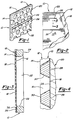
- the filter septum of the invention comprises a metal sheet microscreen element having uniformly distributed apertures through which a liquid to be filtered is passed from an inlet side to an exit side of the element.
- the apertures are formed in the element by an electrochemical process providing a taper in the aperture from a larger diameter at the inlet side to a smaller diameter at the exit side.
- a metal base plate having rows of uniformly distributed holes which are larger than the apertures is permanently bonded to the microscreen element with a layer of brazing alloy between an inlet side of the base plate and the exit side of the microscreen element.
- the inlet side of the microscreen element has a non-stick fluorinated ethylene propylene coating.
- parallel support rods are welded to the exit side of the base plate between selected adjacent rows of the holes and the microscreen sheet and the metal base plate can be made of stainless steel, preferably a 316 or 304 stainless steel.
- the method of producing the filter septum involves the use of a photoetching process to produce the small uniformly distributed apertures in the microscreen element.
- a brazing step an inlet side of the base plate is bonded to the exit side of the microscreen element. If the final form of the filter septum is to be non-planar, for example a cylindrical drum, the base plate will be normally preformed to its final shape prior to brazing.
- the final step of the process is plastic coating the inlet side of the microscreen element with Teflon®.
- the filter septum of the present invention can be sized for application to a variety of filtration septums.
- the star shaped filter 12 described in U.S. Patent 5,221,469 uses a number of panel compartments 40 preferable arranged as shown in diametrically opposed pairs.
- each of the compartments has a pair of opposed septums 86 which are typically made of suitable metal or plastic screen material, and in the embodiments shown they are made of stainless steel wedgewire.
- the microscreen septum of the present invention had not yet been evolved. As will be apparent, there are many advantages of the present microscreen septum over the wedgewire septum, not the least of which is the smaller microscreen aperture over the wedgewire slots which will pass particles of considerable length.
- the desired aperture pattern is first produced through CAD design and transferred to a glass plate photo master.
- the pattern is then transferred in the form of a photosensitive resist to a stainless steel sheet.
- the photoetching process is completed by chemically machining or dissolving the apertures.
- the etching is conducted from both sides of the sheet at different rates to produce a tapered aperture.
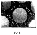
- the stainless steel microscreen sheet can have a thickness between 0.076 mm (0.003") and 0.381 mm (0.015”) and will have a closely spaced aperture pattern with the aperture diameter being between 0.076 mm (0.003") and 0.381 mm (0.015") but never less than the sheet thickness.
- the actual microscreen element in the photograph of the filter septum in FIG. 5 has a thickness of 0.127 mm (0.005") with a hole diameter of 0.152 mm (0.006").
- the microscreen element 12 has an inlet side 14 and an exit side 16 with apertures 18 tapering from a larger diameter at the inlet side to a smaller diameter at the exit side.
- the inlet side diameter can be approximately 0.229 mm (0.009") with the exit side being approximately 0.152 mm (0.006").
- the supporting substrate or base plate 20 of the filter septum 10 will be substantially thicker than the microscreen sheet.
- the base plate 20 is 3.175 mm (11 gage) stainless steel with 9.525 mm (3/8") diameter holes 22 on (12.7 mm) 1/2" centers, punched from exit side 24.
- Reinforcing support rods 26 are welded between adjacent rows of holes 22 on the exit side, and in the example of FIG. 5, the support rods 26 have a 3.175 mm (1/8") diameter and are on 101.6 mm 4" centers. If the final form of the filter septum is to be non-planar, for example a cylindrical drum, the base plate will be normally preformed to its final shape before brazing.
- the filter septum 12 is assembled to the base plate 20 by first spot welding the exit side 16 of the microscreen element 12 to the inlet side 34 of base plate 20 as can be seen in photograph FIG. 5. This is conveniently performed by laser or resistance welding.
- Final assembly of the microscreen element 12 to the base plate 20 is accomplished by furnace brazing so that all of the contact area has a layer of brazing alloy 28 between the exit side 16 of the microscreen element and the inlet side 34 of the base plate.
- a nickel powder alloy is applied to the inlet side of microscreen element and fixed with an acrylic varnish carrier.
- the assembled microscreen element and base panel is loaded horizontally into a vacuum furnace and the temperature is ramped up to melt and wet the metal surface causing the brazing alloy to flow between the exit side of the microscreen element and the inlet side of the base plate permanently bonding the two together.
- a thin fluorinated ethylene propylene coating 30 is applied to the inlet side of 14 of the microscreen element to assist in filter cake release and prevent clogging.
- the coating is Teflon®, fluorinated ethylene propylene, and a single coating of Dupont 958-203 Teflon is sprayed on the surface and baked to assist the air cure.
Landscapes
- Chemical & Material Sciences (AREA)
- Chemical Kinetics & Catalysis (AREA)
- Filtering Materials (AREA)
- Separation Using Semi-Permeable Membranes (AREA)
Claims (8)
- Filterseptum bestehend auseinem aus einer metallischen Folie gebildeten Mikrosiebfolien-Element (12) mit gleichmäßig verteilten Öffnungen (18), durch welche eine zu filtrierende Flüssigkeit von einer Einlaßseite (14) zu einer Auslaßseite (16) des Elements (12) durchtreten kann, undeiner metallische Grundplatte (20), die dicker als die Folie ist und eine Einlaßseite (34) und eine Auslaßseite (24) besitzt,
wobei die Öffnungen (18) in dem Element (12) mittels eines elektrochemischen Prozesses in das Element (12) eingebracht sind, der zur Folge hat, daß sich der Durchmesser der Öffnungen (18) von einem größeren Durchmesser an der Einlaßseite (14) des Elements (12) zu einem kleineren Durchmesser an dessen Auslaßseite (16) verjüngt,
wobei die Grundplatte (20) mit Reihen gleichmäßig verteilter kreisförmiger Löcher (22) versehen ist, die mit einem Durchmesser eingebracht sind, der größer ist als der Durchmesser der Öffnungen (18) an der Einlaßseite (14) des Elementes (12), und
wobei das Element (12) auf die Grundplatte (20) aufgelötet ist, so daß zwischen der Auslaßseite (16) des Elements (12) und der Einlaßseite (34) der Grundplatte (20) eine Schicht Lot-Legierung (28) vorgesehen ist,
dadurch gekennzeichnet,daß auf die Auslaßseite (24) der Grundplatte (20) zwischen benachbarten Reihen von Löchern (22) eine Vielzahl von parallel beabstandeten Stützstäben (26) geschweißt ist unddaß ein Überzug (30) aus fluoriertem Äthylen-Propylen auf der Einlaßseite (14) des Elements (12) vorgesehen ist. - Filterseptum nach Anspruch 1, dadurch gekennzeichnet, daß die Lot-Legierung eine hoch nickelhaltige Legierung ist.
- Filterseptum nach Anspruch 1 oder 2, dadurch gekennzeichnet, daß das Element (12) und die Grundplatte aus rostfreiem Stahl hergestellt sind, wobei das Element eine Dicke zwischen 0,076 mm (0,003") und 0,381 mm (0,015") aufweist, die Öffnungen (18) einen Nenndurchmesser zwischen 0,076 mm ( 0,003") und 0,381 mm (0,015") aufweisen, der jedoch nie kleiner ist als die Dicke des Elements (12), die Grundplatte eine Dicke besitzt, die wenigstens das Achtfache der Dicke des Elementes (12) beträgt, und wobei die Löcher (22) einen Durchmesser besitzen, der wenigstens das Zehnfache des Durchmesser der Öffnungen (18) beträgt.
- Verfahren zum Herstellen eines Filterseptums mit den folgenden Schritten:A) Bilden eines Mikrosiebfolien-Elements (12) durch Anwendung eines Photoätzverfahrens zum Herstellen gleichmäßig verteilter Öffnungen (18) in einer Metallfolie, wobei die Öffnungen einen sich von einem größeren Durchmesser an der Einlaßseite (14) des Elements (12) zu einem kleineren Durchmesser an der Auslaßseite des Elements (12) verjüngenden Durchmesser aufweisen;B) Herstellen einer mit Löchern versehenen metallischen Grundplatte (20), die gleichmäßig verteilte kreisförmige Löcher (22) aufweist, die einen Durchmesser besitzen, der größer ist als der Durchmesser der Öffnungen (18) an der Einlaßseite (14) des Elements (12);C) Verlöten des Elements (12) mit der Grundplatte (20), so daß eine Schicht einer Lot-Legierung (28) zwischen der Auslaßseite (16) des Elements (12) und der Einlaßseite (34) der Grundplatte (20) vorgesehen ist;D) Verstärken der Grundplatte (20) durch Aufschweißen einer Vielzahl von parallelen Stützstäben (26) auf der Auslaßseite (24) der Grundplatte (20) zwischen benachbarten Reihen der Löcher (22) in beabstandeten Intervallen undE) Beschichten der Einlaßseite (14) des Elements (12) durch Aufsprühen einer Schicht aus fluoriertem Äthylen-Propylen (30) auf die Einlaßseite (14) des Elements (12) und Hitzehärten der Schicht aus fluoriertem Äthylen-Propylen zur Unterstützung der Luftaushärtung.
- Verfahren nach Anspruch 4, dadurch gekennzeichnet, daß für die Metallfolie im Verfahrensschritt A und für die Grundplatte (20) im Verfahrensschritt B rostfreier Stahl gewählt wird, wobei die Dicke der Metallfolie zwischen 0,076 mm (0,003") und 0,381 mm (0,015") und der Nenndurchmesser der Öffnungen zwischen 0,076 mm (0,003") und 0,381 mm (0,015"), jedoch nicht kleiner als die Dicke der Metallfolie, gewählt werden.
- Verfahren nach Anspruch 5, wobei für die Grundplatte eine nominelle Dicke von 3,175 mm (11 gage) gewählt wird, und die Löcher (22) einen Durchmesser von ungefähr 9,525 mm (3/8") und um jeweils etwa 12,7 mm (1/2") gegeneinander versetzte Mittelpunkte haben.
- Verfahren nach einem der Ansprüche 4 bis 6, dadurch gekennzeichnet, daß die Auslaßseite (16) des Elements (12) zunächst an einer Vielzahl von Punkten mit der Einlaßseite (34) der Grundplatte (20) verschweißt wird, daß sodann ein pulverförmiges Nickellegierungs-Lötmaterial (28) auf die Auslaßseite (16) des Elements (12) aufgebracht und dort mittels eines Acryllacküberzugs fixiert wird, wobei der Lötvorgang im Verfahrensschritt D in einem Ofen mit gesteuerter Atmosphäre ausgeführt wird.
- Verfahrten nach Anspruch 7, dadurch gekennzeichnet, daß der Lötvorgang in einem Vakuumofen ausgeführt wird, wobei das Element (12) und die Grundplatte (20) in einer horizontalen Position gehalten werden und die Temperatur erhöht wird, um es dem pulverförmigen Lotmaterial (28) zu ermöglichen, zu schmelzen und die aneinander liegenden Oberflächen des Elementes (12) und der Grundplatte (20) zu benetzen und so die Auslaßseite (16) des Elementes (12) mit der Einlaßseite (34) der Grundplatte (20) entlang aller ihrer aneinander anliegenden Oberflächen zu verlöten.
Applications Claiming Priority (2)
| Application Number | Priority Date | Filing Date | Title |
|---|---|---|---|
| US08/146,789 US5399265A (en) | 1993-11-02 | 1993-11-02 | Filter septum |
| US146789 | 1993-11-02 |
Publications (2)
| Publication Number | Publication Date |
|---|---|
| EP0650754A1 EP0650754A1 (de) | 1995-05-03 |
| EP0650754B1 true EP0650754B1 (de) | 1998-06-03 |
Family
ID=22519012
Family Applications (1)
| Application Number | Title | Priority Date | Filing Date |
|---|---|---|---|
| EP94116848A Expired - Lifetime EP0650754B1 (de) | 1993-11-02 | 1994-10-25 | Filterseptum |
Country Status (5)
| Country | Link |
|---|---|
| US (1) | US5399265A (de) |
| EP (1) | EP0650754B1 (de) |
| CA (1) | CA2134157C (de) |
| DE (1) | DE69410743T2 (de) |
| ES (1) | ES2118296T3 (de) |
Families Citing this family (26)
| Publication number | Priority date | Publication date | Assignee | Title |
|---|---|---|---|---|
| DE4402547C1 (de) * | 1994-01-28 | 1995-03-23 | Stockhausen Chem Fab Gmbh | Vorrichtung und Verfahren zum Auflösen von wasserlöslichen, pulverförmigen Polymerisaten |
| JP3187249B2 (ja) * | 1994-05-17 | 2001-07-11 | 本田技研工業株式会社 | スラッジ除去装置 |
| DE29514868U1 (de) * | 1995-09-15 | 1995-11-23 | Heinrich Fiedler GmbH & Co. KG, 93057 Regensburg | Filter aus Blechmaterial |
| US5738787A (en) * | 1995-10-30 | 1998-04-14 | Imc-Agrico Company | Filter pan |
| US5632891A (en) * | 1995-11-17 | 1997-05-27 | Purolator Products Company | Self venting septums for use in a liquid filtration system |
| US5975312A (en) * | 1997-08-28 | 1999-11-02 | Black, Sivalls & Bryson, Limited (Canada) | Fluid filter |
| US6280013B1 (en) | 1997-11-05 | 2001-08-28 | Hewlett-Packard Company | Heat exchanger for an inkjet printhead |
| DE19804493B4 (de) * | 1998-02-05 | 2008-03-27 | Pall Corp. | Filtermedium für die Fest/Flüssig-Trennung |
| US6086195A (en) * | 1998-09-24 | 2000-07-11 | Hewlett-Packard Company | Filter for an inkjet printhead |
| US6372472B1 (en) | 1999-09-24 | 2002-04-16 | Swim Pure Corporation | Filter media containing powered cellulose and immobilized lipase for swimming pool and spa water filteration |
| GB2366927B (en) * | 2000-09-07 | 2003-03-26 | Guy Spencer Edney | Projection unit |
| AU2005203204B2 (en) * | 2000-09-07 | 2007-06-28 | Guy Spencer Edney | Projection Unit |
| DE10056518A1 (de) * | 2000-11-15 | 2002-05-23 | Bhs Sonthofen Maschinen & Anlagenbau Gmbh | Filterplatte, Verfahren zur Herstellung der Filterplatte, Verwendung der Filterplatte in einem Drehfilter |
| US20040129651A1 (en) * | 2001-04-11 | 2004-07-08 | Guy Vanhoutte | Metal fiber filter element |
| US7252764B2 (en) * | 2001-05-15 | 2007-08-07 | California Institute Of Technology | Method for fabrication of a molecular filter and apparatus formed by the same |
| DE10147760A1 (de) * | 2001-09-27 | 2003-04-10 | Mann & Hummel Filter | Mehrlagiges Filterelement |
| US6692637B2 (en) * | 2001-11-07 | 2004-02-17 | Tetra Holding (Us), Inc. | Dual density filter cartridge |
| DE10316173B4 (de) * | 2003-04-04 | 2006-03-16 | Hans Huber Ag Maschinen- Und Anlagenbau | Vorrichtung zum Entfernen von feinem Siebgut aus einer Flüssigkeit |
| US7410569B1 (en) | 2005-11-18 | 2008-08-12 | Turhan A. Tilev | Filtration system for metalworking fluids |
| JP4581987B2 (ja) * | 2005-12-16 | 2010-11-17 | ブラザー工業株式会社 | インクジェットヘッド及びその製造方法 |
| DE102006005807A1 (de) * | 2006-02-08 | 2007-08-16 | BSH Bosch und Siemens Hausgeräte GmbH | Filterelement für Dunstabzugshaube |
| US20110288319A1 (en) * | 2010-05-20 | 2011-11-24 | Tlp Investments Llc | Filter for deep fryer |
| US9421317B2 (en) | 2012-06-08 | 2016-08-23 | Pall Corporation | Cell harvesting device and system |
| US9427512B2 (en) * | 2012-06-08 | 2016-08-30 | Pall Corporation | Filter device |
| WO2016145198A1 (en) | 2015-03-10 | 2016-09-15 | Viatar LLC | Systems, methods, and devices for removing circulating tumor cells from blood |
| US12435835B2 (en) * | 2022-08-17 | 2025-10-07 | Caterpillar Inc. | Screen assembly |
Family Cites Families (11)
| Publication number | Priority date | Publication date | Assignee | Title |
|---|---|---|---|---|
| US3780872A (en) * | 1968-05-27 | 1973-12-25 | Pall Corp | Filters comprising anisometric compressed and bonded multilayer knitted wire mesh composites |
| FR1582091A (de) * | 1968-05-30 | 1969-09-26 | ||
| US3679062A (en) * | 1969-12-17 | 1972-07-25 | Ambac Ind | Filter leaf and method of making the same |
| US3984044A (en) * | 1973-10-01 | 1976-10-05 | Composite Sciences, Inc. | Retention means for mechanical separation and process of making same |
| US4169059A (en) * | 1977-01-10 | 1979-09-25 | Brunswick Corporation | Autogenously bonded filter assemblies |
| US4234430A (en) * | 1979-03-01 | 1980-11-18 | Multi-Metal Wire Cloth Inc. | Filtering septum |
| JPS60244315A (ja) * | 1984-05-17 | 1985-12-04 | Nagaoka Kinmo Kk | 円筒スクリ−ンおよびその製造方法 |
| FR2577345B1 (fr) * | 1985-02-08 | 1989-09-22 | Framatome Sa | Dispositif de filtration d'un liquide en circulation dans le circuit de refroidissement d'un reacteur nucleaire et procede de fabrication de ce dispositif |
| DE3622623A1 (de) * | 1986-07-05 | 1988-01-14 | Man Nutzfahrzeuge Gmbh | Verfahren und vorrichtung zum beseitigen von in einem abgasfilter einer brennkraftmaschine abgeschiedenem russ |
| US5200072A (en) * | 1990-08-16 | 1993-04-06 | Ahlstrom Screen Plates Inc. | Screen plates and methods of manufacture |
| US5221469A (en) * | 1991-12-09 | 1993-06-22 | Hydroflow, Inc. | Filtration system |
-
1993
- 1993-11-02 US US08/146,789 patent/US5399265A/en not_active Expired - Lifetime
-
1994
- 1994-10-24 CA CA002134157A patent/CA2134157C/en not_active Expired - Fee Related
- 1994-10-25 EP EP94116848A patent/EP0650754B1/de not_active Expired - Lifetime
- 1994-10-25 ES ES94116848T patent/ES2118296T3/es not_active Expired - Lifetime
- 1994-10-25 DE DE69410743T patent/DE69410743T2/de not_active Expired - Fee Related
Also Published As
| Publication number | Publication date |
|---|---|
| CA2134157A1 (en) | 1995-05-03 |
| DE69410743T2 (de) | 1998-12-24 |
| ES2118296T3 (es) | 1998-09-16 |
| EP0650754A1 (de) | 1995-05-03 |
| CA2134157C (en) | 2004-11-30 |
| US5399265A (en) | 1995-03-21 |
| DE69410743D1 (de) | 1998-07-09 |
Similar Documents
| Publication | Publication Date | Title |
|---|---|---|
| EP0650754B1 (de) | Filterseptum | |
| JP3294629B2 (ja) | 排ガス接触浄化装置及びその製造方法 | |
| US4770740A (en) | Method of manufacturing valve element for use in an ink-jet printer head | |
| US4872888A (en) | Microporous membrane filter and method of producing same | |
| DE19983751B4 (de) | Wasserstoff-Abtrennungs-Membran | |
| JP2018111097A (ja) | セラミックフィルタ | |
| US6036832A (en) | Electroforming method, electroforming mandrel and electroformed product | |
| EP0272764A1 (de) | Membran mit Perforationen, Verfahren zu deren Herstellung und Trennungseinrichtung, welche eine oder mehrere solche Membranen umfasst | |
| US20040060867A1 (en) | Membrane support devices and methods of manufacturing | |
| JP2011147872A (ja) | 積層焼結フィルター | |
| US6318565B1 (en) | Filtration member for solid-liquid separation | |
| JP2004225126A (ja) | 成膜用マスクとその製造方法 | |
| US9776111B2 (en) | Disc shaped filter element | |
| CN101291738A (zh) | 穿孔部件 | |
| US4797175A (en) | Method for making solid element fluid filter for removing small particles from fluids | |
| US3679062A (en) | Filter leaf and method of making the same | |
| JP2005138083A (ja) | 金網フィルタ | |
| US4968423A (en) | Filter leaf | |
| JPH0611371B2 (ja) | 瀘過ないし分離用円筒状素子の製造方法 | |
| JP2761352B2 (ja) | フィルターの製造方法及びフィルター並びにこのフィルターを取付けたガス器具 | |
| JP3884133B2 (ja) | 積層金属フィルター | |
| JPH0233121B2 (de) | ||
| EP0240265B1 (de) | Matrize zum Extrudieren von keramischen Gegenständen in Honigwabenstruktur | |
| JP3538212B2 (ja) | 精密積層濾過材 | |
| EP3721974B1 (de) | Flachmembranelement und verfahren zu seiner herstellung |
Legal Events
| Date | Code | Title | Description |
|---|---|---|---|
| PUAI | Public reference made under article 153(3) epc to a published international application that has entered the european phase |
Free format text: ORIGINAL CODE: 0009012 |
|
| AK | Designated contracting states |
Kind code of ref document: A1 Designated state(s): DE ES FR GB IT |
|
| RTI1 | Title (correction) | ||
| 17P | Request for examination filed |
Effective date: 19951031 |
|
| 17Q | First examination report despatched |
Effective date: 19961023 |
|
| GRAG | Despatch of communication of intention to grant |
Free format text: ORIGINAL CODE: EPIDOS AGRA |
|
| GRAG | Despatch of communication of intention to grant |
Free format text: ORIGINAL CODE: EPIDOS AGRA |
|
| GRAH | Despatch of communication of intention to grant a patent |
Free format text: ORIGINAL CODE: EPIDOS IGRA |
|
| GRAH | Despatch of communication of intention to grant a patent |
Free format text: ORIGINAL CODE: EPIDOS IGRA |
|
| GRAA | (expected) grant |
Free format text: ORIGINAL CODE: 0009210 |
|
| AK | Designated contracting states |
Kind code of ref document: B1 Designated state(s): DE ES FR GB IT |
|
| REF | Corresponds to: |
Ref document number: 69410743 Country of ref document: DE Date of ref document: 19980709 |
|
| ITF | It: translation for a ep patent filed | ||
| ET | Fr: translation filed | ||
| REG | Reference to a national code |
Ref country code: ES Ref legal event code: FG2A Ref document number: 2118296 Country of ref document: ES Kind code of ref document: T3 |
|
| PLBE | No opposition filed within time limit |
Free format text: ORIGINAL CODE: 0009261 |
|
| STAA | Information on the status of an ep patent application or granted ep patent |
Free format text: STATUS: NO OPPOSITION FILED WITHIN TIME LIMIT |
|
| 26N | No opposition filed | ||
| REG | Reference to a national code |
Ref country code: GB Ref legal event code: IF02 |
|
| PGFP | Annual fee paid to national office [announced via postgrant information from national office to epo] |
Ref country code: FR Payment date: 20041008 Year of fee payment: 11 |
|
| PGFP | Annual fee paid to national office [announced via postgrant information from national office to epo] |
Ref country code: DE Payment date: 20041021 Year of fee payment: 11 |
|
| PGFP | Annual fee paid to national office [announced via postgrant information from national office to epo] |
Ref country code: ES Payment date: 20041116 Year of fee payment: 11 |
|
| PG25 | Lapsed in a contracting state [announced via postgrant information from national office to epo] |
Ref country code: IT Free format text: LAPSE BECAUSE OF NON-PAYMENT OF DUE FEES;WARNING: LAPSES OF ITALIAN PATENTS WITH EFFECTIVE DATE BEFORE 2007 MAY HAVE OCCURRED AT ANY TIME BEFORE 2007. THE CORRECT EFFECTIVE DATE MAY BE DIFFERENT FROM THE ONE RECORDED. Effective date: 20051025 |
|
| PG25 | Lapsed in a contracting state [announced via postgrant information from national office to epo] |
Ref country code: ES Free format text: LAPSE BECAUSE OF NON-PAYMENT OF DUE FEES Effective date: 20051026 |
|
| PGFP | Annual fee paid to national office [announced via postgrant information from national office to epo] |
Ref country code: GB Payment date: 20051026 Year of fee payment: 12 |
|
| PG25 | Lapsed in a contracting state [announced via postgrant information from national office to epo] |
Ref country code: DE Free format text: LAPSE BECAUSE OF NON-PAYMENT OF DUE FEES Effective date: 20060503 |
|
| PG25 | Lapsed in a contracting state [announced via postgrant information from national office to epo] |
Ref country code: FR Free format text: LAPSE BECAUSE OF NON-PAYMENT OF DUE FEES Effective date: 20060630 |
|
| REG | Reference to a national code |
Ref country code: FR Ref legal event code: ST Effective date: 20060630 |
|
| REG | Reference to a national code |
Ref country code: ES Ref legal event code: FD2A Effective date: 20051026 |
|
| GBPC | Gb: european patent ceased through non-payment of renewal fee |
Effective date: 20061025 |
|
| PG25 | Lapsed in a contracting state [announced via postgrant information from national office to epo] |
Ref country code: GB Free format text: LAPSE BECAUSE OF NON-PAYMENT OF DUE FEES Effective date: 20061025 |