EP0648985A2 - Solar absorber and process of producing the same - Google Patents
Solar absorber and process of producing the same Download PDFInfo
- Publication number
- EP0648985A2 EP0648985A2 EP94116154A EP94116154A EP0648985A2 EP 0648985 A2 EP0648985 A2 EP 0648985A2 EP 94116154 A EP94116154 A EP 94116154A EP 94116154 A EP94116154 A EP 94116154A EP 0648985 A2 EP0648985 A2 EP 0648985A2
- Authority
- EP
- European Patent Office
- Prior art keywords
- pipeline
- holding jaws
- holding
- solar absorber
- jaws
- Prior art date
- Legal status (The legal status is an assumption and is not a legal conclusion. Google has not performed a legal analysis and makes no representation as to the accuracy of the status listed.)
- Granted
Links
Images


Classifications
-
- F—MECHANICAL ENGINEERING; LIGHTING; HEATING; WEAPONS; BLASTING
- F24—HEATING; RANGES; VENTILATING
- F24S—SOLAR HEAT COLLECTORS; SOLAR HEAT SYSTEMS
- F24S10/00—Solar heat collectors using working fluids
- F24S10/70—Solar heat collectors using working fluids the working fluids being conveyed through tubular absorbing conduits
- F24S10/75—Solar heat collectors using working fluids the working fluids being conveyed through tubular absorbing conduits with enlarged surfaces, e.g. with protrusions or corrugations
-
- F—MECHANICAL ENGINEERING; LIGHTING; HEATING; WEAPONS; BLASTING
- F24—HEATING; RANGES; VENTILATING
- F24S—SOLAR HEAT COLLECTORS; SOLAR HEAT SYSTEMS
- F24S10/00—Solar heat collectors using working fluids
- F24S10/70—Solar heat collectors using working fluids the working fluids being conveyed through tubular absorbing conduits
- F24S2010/71—Solar heat collectors using working fluids the working fluids being conveyed through tubular absorbing conduits the conduits having a non-circular cross-section
-
- F—MECHANICAL ENGINEERING; LIGHTING; HEATING; WEAPONS; BLASTING
- F24—HEATING; RANGES; VENTILATING
- F24S—SOLAR HEAT COLLECTORS; SOLAR HEAT SYSTEMS
- F24S25/00—Arrangement of stationary mountings or supports for solar heat collector modules
- F24S25/60—Fixation means, e.g. fasteners, specially adapted for supporting solar heat collector modules
- F24S2025/6004—Fixation means, e.g. fasteners, specially adapted for supporting solar heat collector modules by clipping, e.g. by using snap connectors
-
- Y—GENERAL TAGGING OF NEW TECHNOLOGICAL DEVELOPMENTS; GENERAL TAGGING OF CROSS-SECTIONAL TECHNOLOGIES SPANNING OVER SEVERAL SECTIONS OF THE IPC; TECHNICAL SUBJECTS COVERED BY FORMER USPC CROSS-REFERENCE ART COLLECTIONS [XRACs] AND DIGESTS
- Y02—TECHNOLOGIES OR APPLICATIONS FOR MITIGATION OR ADAPTATION AGAINST CLIMATE CHANGE
- Y02E—REDUCTION OF GREENHOUSE GAS [GHG] EMISSIONS, RELATED TO ENERGY GENERATION, TRANSMISSION OR DISTRIBUTION
- Y02E10/00—Energy generation through renewable energy sources
- Y02E10/40—Solar thermal energy, e.g. solar towers
- Y02E10/44—Heat exchange systems
Definitions
- the present invention relates to a solar absorber with the features of the preamble of claim 1 and claim 2, as is known from DE 92 13 151 U1.
- the present invention is therefore based on the object of providing a solar absorber of the type mentioned at the outset which, in comparison with conventional solar absorbers with simple manufacture, also ensures good long-term heat transfer between the pipeline carrying the heat transfer medium and the absorber plate.
- a solar absorber with holding jaws which are at least approximately the same length, ie which surround the pipe at least approximately the same distance, in that the pipe has a single indentation, which is arranged in the region of its secondary apex lying away from the absorber plate and which preferably has an essentially continuously running curved shape. At least one of the two holding jaws preferably engages with its free edge in the indentation of the pipeline.
- the two holding jaws encompass the pipe at different distances, easier installation is possible since the pipe can be pivoted into the space between the two holding jaws and then - together with or separately from the holding jaws - brought into the desired final shape.
- the production method comprises the following steps: inserting the elliptical or pear-shaped pipeline, which is round in cross section, between the two holding jaws, Forming the cross-section of the pipeline so that areas of the wall of the pipeline located between the active flanks of the holding jaws rest firmly and essentially positively on the active flanks of the holding jaws, and the cross-section of the pipeline between the holding jaws essentially corresponds to the shape of at least a section of an ellipse or oval assumes whose secondary apex in the first plane running between the holding jaws and the main apex in a substantially parallel to or to the absorber plate the first level transverse second level are arranged.
- the pipeline can have the cross-sectional shape that it needs for positive engagement with the active surfaces of the holding jaws.
- the shape of the pipeline can only be imparted when it is between the two holding jaws.
- the holding jaws to be deformed are already preformed in such a way that they are inclined towards the pipeline bed. They therefore need to be deformed less later, which reduces the risk of the holding jaws breaking, and the shaping process is simpler since the pressure required for the shaping can be applied from the beginning rather than from the side essentially from above.
- At least one of the two holding jaws has at least one weakening area.
- Weaker manufacturing devices can then be used and the shaping process can optionally be carried out in one step.
- the provision of such weakening areas can also be used to control the course of the curvature and thus the optimal contact of the wall of the pipeline with the active surfaces of the holding jaws.
- the weakened area preferably has the shape of a recess running parallel to the free edge of the holding jaw.
- the notch-shaped recess for example, can be arranged on the outside of a holding jaw, but it is preferably on the inside of a pipe facing the pipeline Holding jaws arranged.
- a holding jaw can also have a plurality of recesses which are arranged at a distance from one another in the transverse direction and preferably run parallel to one another. In this way, the desired final shape of the pipeline can be controlled even more differentially, for example, when the holding jaw (s) are pressed against the pipeline.
- the pipeline has an indentation in the region of its secondary apex lying away from the absorber plate, which has an essentially continuously curved shape.
- the reshaping of the cross section of the pipeline, the pressing of the holding jaw (s) onto the pipeline, and the shaping of the indentation take place in a single operation.
- a roller machine in which one or more rollers moving along the corresponding pipeline press the holding jaw (s) onto the pipeline and at the same time form the indentation in the region of the secondary apex of the pipeline remote from the absorber plate is particularly suitable for such an operation. In this way, very long absorber profiles can also be produced inexpensively.
- At least one of the two holding jaws preferably engages with its free edge in the indentation of the pipeline.
- At least one of the two holding jaws is formed from a plurality of parts which are detachably connected to one another.
- a specific embodiment of this consists in that one of the two parts of the holding jaws has a hook which engages in a correspondingly shaped catch on the other part of the holding jaw.
- At least one of the two holding jaws has raised areas on its active surface which engage in a form-fitting manner in the wall of the pipeline. This applies in particular if the absorber plate or the holding jaws arranged thereon are made of aluminum and the pipeline is made of softer copper.
- a preferred embodiment of the manufacturing method of the solar absorber according to the invention is that at least one of the two holding jaws takes up a position before inserting the pipeline, which enables the pipeline to be inserted between the holding jaws, and that after the pipeline is inserted between the holding jaws, a force is exerted on at least one one of the two holding jaws is exerted in such a way that it is deformed together with the pipeline in such a way that the areas of the wall of the pipeline fit positively on the active surfaces of the holding jaws.
- At least one of the two holding jaws can assume a position before inserting the pipeline, which enables the pipeline to be inserted between the holding jaws, a force being exerted on the pipeline between the holding jaws after the pipeline has been inserted, so that the wall of the pipeline extends Apply at least partially positively to the active surfaces of the holding jaws, and then a force is exerted on at least one of the two holding jaws in such a way that its active surfaces positively contact the areas of the wall of the pipeline.
- the pipeline is usually either meandering in a solar absorber, with only the straight areas of the meandering pipeline being clamped between holding jaws, or there are several pipelines running parallel to one another in a solar absorber, the ends of which are connected to one another by manifolds. Even with the last-mentioned design of a solar absorber, only the pipes running parallel to one another are clamped by means of holding jaws.
- the parallel pipelines or the parallel pipeline sections of a meandering bent pipeline can have different lengths.
- the solar absorber has a shape that deviates from the usual square or rectangular shape, for example a triangular, pentagonal, hexagonal or octagonal shape in plan view.
- the pipes inserted between the holding jaws are deformed in such a way that all the pipes or pipe sections of the solar absorber have the same pressure loss. This is achieved by deforming the individual pipes or pipe sections to different degrees after insertion.
- a pipe that is shorter than the other pipes is deformed after being inserted so that it has a smaller flow cross-section, whereby its pressure loss value is increased to the value of the pressure loss of a longer pipe with a larger flow cross-section.
- the deformation of the pipeline can, as described above, either be carried out by directly deforming the pipeline after it has been inserted between the holding jaws, or indirectly by deforming the holding jaw or jaws, which then deform the pipeline enclosed between them accordingly. Setting the differently long pipelines or pipeline sections to at least substantially the same pressure loss prevents the undesirable state of an uneven one Flow through the individual pipes or pipe sections into a solar absorber.
- an indentation is formed in the pipeline in the region of its secondary apex lying away from the absorber plate, which indentation takes on an essentially continuously running curved shape.
- Such an indentation allows pipes or pipe sections of different lengths to be adjusted even better to the same pressure loss, for example when a pipe inserted between the holding jaws can no longer deflect laterally in the pipe bed, although its flow cross-section must still be reduced in order to achieve the desired pressure loss value .
- the pipeline bed in the region of the secondary apex adjacent to the absorber plate can have a bulge, which is preferably continuously curved and extends along the pipeline bed.
- a bulge supports the natural shape finding of a round or oval pipeline in the initial state, because when such pipelines are flattened, the circumferential wall of the pipeline begins to bulge inward when a certain deformation state has been exceeded.
- the bulge in the pipeline bed supports this natural tendency of a pipeline to deform and allows it to occur at a defined point, while at the same time ensuring that this part of the circumferential wall of the pipeline that otherwise stands out from the pipeline bed remains in heat-conducting contact with the pipeline bed.
- a force is exerted on at least one of the two holding jaws, which forces it with its free edge into the indentation of the pipeline.
- the free edge is at least one of the holding jaws so designed that even after the deformation of the holding jaw and its positive contact with the outer surface of the pipeline thereby achieved, it is ensured that a tool can grip between the holding jaws and the pipeline in order to detach the holding jaws from the pipeline if necessary. This is important, on the one hand, in order to be able to repair after a faulty deformation process, and, on the other hand, it is important in connection with a later recycling of the solar absorber, in order to be able to separate copper pipes from an aluminum absorber plate by bending the holding jaws .
- An intermediate space between the outer surface of the pipeline and the free edge of the holding jaw pressed against it is advantageously achieved by the free edge of the holding jaw on its side facing the pipeline having a recess running along the pipeline.
- the last piece of the free edge of the holding jaw (s) can be bent slightly upwards, so that a tool can reach under the holding jaw (s) on the free edge.
- an indentation is formed in their pipeline in the area of their secondary apex lying away from the absorber plate, the possibility of a tool attack can also be created by not pressing the free edge of the holding jaw (s) into the indentation.
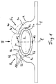
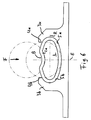
- Fig. 1 shows a solar absorber consisting of an absorber plate 1 which is essentially rectangular in cross section and a pipeline 2 which carries a heat transport medium (brine, oil or the like) which is not shown, both of which are made of a good heat-conducting material, e.g. Aluminum, copper or the like are formed.
- the pipeline 2 is fastened to the absorber plate 1 by means of two holding jaws 3a, 3b arranged at a distance from one another on the absorber plate 1.
- the holding jaws 3a, 3b are integrally formed on the absorber plate 1 and of the same material and each have a cross-sectional shape tapering towards their free edge 4a, 4b.
- the holding jaws 3a, 3b are convex in cross-section at their mutually facing active flanks 5a, 5b and each taper towards one another in such a way that there is an approximately half-elliptical-shaped space between them.
- Fig. 1 the two holding jaws 3a, 3b and the pipeline 2 are shown in dash-dotted lines in a position which they are in front of have the assembly to the solar absorber.
- the two holding jaws 3a, 3b assume a position which is inclined to the absorber plate 1 but is more vertical; the pipe 2 is circular in cross section and is inserted into the free space between the active flanks 5a, 5b of the holding jaws 3a, 3b.
- the wall 2a of the pipeline 2 between the active flanks 5a, 5b of the holding jaws 3a, 3b is deformed by a force F in such a way that the wall 2a, at least in the half facing the absorber plate 1, is firmly and essentially positively on the active flanks 5a, 5b of the holding jaws 3a, 3b abuts.
- the free edges 4a, 4b of the two holding jaws 3a, 3b are pressed onto the pipeline 2 by the forces G1, G2 such that the clear cross section of the pipeline 2 between the holding jaws 3a, 3b essentially has the shape of at least a section of an ellipse or an oval, whose secondary apex N1, N2 in a first plane E running between the holding jaws 3a, 3b and whose main apex H1, H2 in a plane parallel to the absorber plate 1 or transverse to the first plane E.
- second level R are arranged.
- the two holding jaws 3a, 3b are designed symmetrically to the first plane E, that is to say that the two holding jaws 3a, 3b also encompass the pipeline 2 to the same extent.
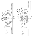
- the holding jaws 3a ', 3b' are asymmetrically shaped and encompass the pipeline 2 to different extents.
- the pipeline 2 has an essentially circular cross section and is inserted into the free space between an undeformable holding jaw 3b 'and a deformable holding jaw 3a'.
- the holding jaw 3a ' has a weakening region 7 which has the shape of a recess running parallel to the free edge 4a of the holding jaw.
- the pipeline 2 or the holding jaws 3a ' has the shape shown continuously in FIG. 2, that is to say the pipeline 2 lies firmly and positively on the active surfaces 5a, 5b of the holding jaws 3a', 3b ' .
- the half of the pipeline 2 which is remote from the absorber plate 1 has an asymmetrical shape in that it is not oval-shaped but flattened by the holding jaws 3a ', which largely reforms the pipeline 2 and thus a form-fitting and good heat transfer connection between the active surfaces 5a, 5b and the wall 2a of the pipeline 2 means.
- the embodiment according to FIG. 3 is only a modification compared to FIG. 1 in that the pipeline 2 additionally has an indentation 8 in the area of its secondary apex N2 remote from the absorber plate 1, which recess is essentially continuous has a curved shape.
- the indentation 8 is produced after the assembly of the pipeline 2 and the shaping of the holding jaws 3a, 3b by the forces F, G1, G2 in that an additional force H is applied to the wall 2a of the pipeline 2, which in the first plane E works.
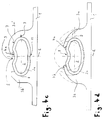
- the pipeline 2 has an oval cross-sectional shape even before it is inserted into the free space between the holding jaws 3a ', 3b', so that the pipeline 2 easily moves into the free space between the holding jaws 3a ', 3b 'can be inserted.
- the holding jaws 3a ', 3b' here have essentially the same shape as in Fig. 2, that is, the holding jaws 3a 'is extended to such an extent that it almost reaches the plane E when it is pressed into the is formed with solid lines drawn position, in which it encloses the pipe 2 firmly and positively.
- the force H is then exerted on the free edge 4a and the secondary apex N2 of the wall 2a of the pipeline 2, so that the indentation 8 is formed in the wall 2a of the pipeline 2 and the free edge 4a of the holding jaw 3a 'at least partially in the indentation 8 engages (see Fig. 4b).
- the holding jaws are preferably so long (see, for example, FIG. 4e) that their free edge can be pressed into the indentation 8.
- FIG. 4c shows a somewhat modified fourth embodiment, in which the holding jaw 3a 'does not have a weakening region 7 on the outside, as in FIG. 2, but two parallel weakening regions 7 on the inside of the holding jaw 3a'.
- the weakened areas 7 shown in FIG. 4c have an approximately V-shaped cross section and extend along the holding jaw 3a '.
- the free edge 4a of the holding jaw 3a ' has a longitudinally extending recess 9, by which it is ensured that the holding jaw 3a' pressed against the pipeline 2 can be gripped and bent up again by a tool, for example in the context of recycling operations To be able to separate pipe 2 from the absorber plate 1.
- the holding jaw 3b also has a recess 9 on its free edge.
- the free edge of the holding jaw (s), here the free edges 4a and 4b of the holding jaws 3a and 3b can be raised somewhat, i.e. be bent away from the outer surface of the pipeline 2, so as to enable a tool (not shown) to be reached under.
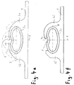
- the tool attack required to bend the holding jaw or the holding jaws can take place can also be provided in a simple manner in that the free edge 4a and / or 4b of the holding jaws 3a, 3b or 3a 'is not pressed into the indentation 8 (see FIGS. 4e and 4f).
- the embodiment shown in FIG. 4c also differs from the embodiments shown in the other figures in that a raised, continuously curved bulge 11 is present in the pipe bed in the region of the secondary apex N1 facing the absorber plate.
- the bulge 11 extends along the pipeline bed and supports the natural shaping of the pipeline 2 during the forming process. Even in the case of extensive forming processes compared to the initial shape of the pipeline 2, the bulge 11 ensures a heat-conducting contact between the absorber plate 1 and the pipeline 2, which would not occur in this area without the bulge 11 due to the bulging of the pipeline 2 when the pipeline 2 is strongly deformed would be more available.
- the holding jaw 3a is made of two parts 13a, 23a, which are detachably connected to one another.
- the part 13a has a hook 14 which engages in a correspondingly shaped catch 15 on the other part 23a of the holding jaw 3a and is releasably locked to it.
- the wall 2a of the pipeline 2 already has an oval cross-sectional shape before the mounting of the holding jaw 3a, which corresponds to the shape of the active surface 5a, 5b.
- the side of which faces the wall 2a of the pipeline 2 also substantially corresponds to the shape of the pipeline 2 in this area, there is also an intimate heat-conducting contact between the active surfaces 5a, 5b and the wall 2a in this embodiment the pipeline 2 guaranteed.
- the surfaces 16, 17 on the two parts of the holding jaw 3a are worked so precisely that no significant heat transfer losses occur there.
- both holding jaws 3a, 3b are designed to be non-deformable and their free edges 4a, 4b are spaced apart from one another in such a way that the pipe 2, which is circular in cross section in the initial state, can be introduced into the free space between the two holding jaws 3a, 3b .
- the active surfaces 5a, 5b of the two holding jaws 3a, 3b have an elliptical-shell-shaped cross-section, into which the pipeline 2 is brought by a force F acting in the first plane E, which causes the wall 2a of the pipeline 2 to be form-fitting and clings firmly to the active surfaces 5a, 5b of the holding jaws 3a, 3b.
- An indentation 8 is then worked into the area of the wall 2a of the pipeline facing away from the absorber plate 1 in the manner described above.
- the holding jaws 3a, 3b can have raised areas 18 on their active surfaces 5a, 5b, which engage in a form-fitting manner in the wall 2a of the pipeline 2 (see, for example, FIG. 1).
- first plane E and the second plane R run at right angles to one another, and the first plane E runs parallel to the absorber plate 1.
- the first plane E can also be inclined with respect to the absorber plate 1.
Landscapes
- Engineering & Computer Science (AREA)
- Chemical & Material Sciences (AREA)
- Combustion & Propulsion (AREA)
- Mechanical Engineering (AREA)
- Physics & Mathematics (AREA)
- Sustainable Development (AREA)
- Sustainable Energy (AREA)
- Thermal Sciences (AREA)
- Dispersion Chemistry (AREA)
- Life Sciences & Earth Sciences (AREA)
- General Engineering & Computer Science (AREA)
- Rigid Pipes And Flexible Pipes (AREA)
- Supports For Pipes And Cables (AREA)
- Hybrid Cells (AREA)
- Special Spraying Apparatus (AREA)
- Diaphragms For Electromechanical Transducers (AREA)
- Inorganic Insulating Materials (AREA)
Abstract
Description
Die Vorliegende Erfindung betrifft einen Solarabsorber mit den Merkmalen des Oberbegriffs des Anspruchs 1 bzw. des Anspruchs 2, wie er aus der DE 92 13 151 U1 bekannt ist.The present invention relates to a solar absorber with the features of the preamble of
Aus der DE 34 27 369 C2 ist ein Solarabsorber bzw. ein Verfahren Zu dessen Herstellung bekannt, bei dem die Ellipsen-Hauptachse der Rohrleitung senkrecht zur Absorberplatte verläuft. Diese Anordnung hat zwar den Vorteil, daß ein sehr inniger Kontakt der Rohrleitung mit den Wirkflanken der Haltebacken vorhanden ist, der auch einfach wieder hergestellt werden kann, wenn sich im Laufe des Betriebes des Solarabsorbers der Kontakt wegen der Wärmeexpansion und -kontraktion Verschlechtern sollte.From DE 34 27 369 C2 a solar absorber or a method for its production is known in which the main ellipse axis of the pipeline runs perpendicular to the absorber plate. This arrangement has the advantage that there is a very intimate contact of the pipeline with the active flanks of the holding jaws, which can also be easily restored if the contact should deteriorate due to the heat expansion and contraction during the operation of the solar absorber.
Allerdings erfordert diese Anordnung relativ viel Platzbedarf in der Richtung quer zur Absorberplatte. Außerdem bewirkt die lange Wärmeleitung durch die Haltebacken einen verringerten Wirkungsgrad des bekannten Solarabsorbers.However, this arrangement requires a relatively large amount of space in the direction transverse to the absorber plate. In addition, the long heat conduction through the holding jaws reduces the efficiency of the known solar absorber.
Der vorliegenden Erfindung liegt daher die Aufgabe zugrunde, einen Solarabsorber der eingangs genannten Art bereitzustellen, der im Vergleich zu herkömmlichen Solarabsorbern bei einfacher Herstellbarkeit eine auch langfristig gute Wärmeübertragung zwischen der den Wärmeträger führenden Rohrleitung und der Absorberplatte sicherstellt.The present invention is therefore based on the object of providing a solar absorber of the type mentioned at the outset which, in comparison with conventional solar absorbers with simple manufacture, also ensures good long-term heat transfer between the pipeline carrying the heat transfer medium and the absorber plate.
Diese Aufgabe ist bei einem Solarabsorber mit zumindest annähernd gleich langen, d.h. die Rohrleitung zumindest ungefähr gleich weit umgreifenden Haltebacken erfindungsgemäß dadurch gelöst, daß die Rohrleitung eine einzige Einbuchtung aufweist, die im Bereich ihres von der Absorberplatte abliegenden Nebenscheitels angeordnet ist und die Vorzugsweise eine im wesentlichen stetig verlaufende gewölbte Form hat. Bevorzugt greift wenigstens einer der beiden Haltebacken mit seinem freien Rand in die Einbuchtung der Rohrleitung ein.This object is achieved according to the invention in a solar absorber with holding jaws which are at least approximately the same length, ie which surround the pipe at least approximately the same distance, in that the pipe has a single indentation, which is arranged in the region of its secondary apex lying away from the absorber plate and which preferably has an essentially continuously running curved shape. At least one of the two holding jaws preferably engages with its free edge in the indentation of the pipeline.
Die erwähnte, einzige Einbuchtung führt überraschenderweise dazu, daß die zwischen den beiden Haltebacken eingeklemmte Rohrleitung trotz der großen in einem Solarabsorber auftretenden Temperaturunterschiede bzw. -schwankungen dauerhaft fest im von der Absorberplatte und den beiden Haltebacken gebildeten Rohrleitungsbett gehalten ist, wodurch ein langfristig guter und im wesentlichen gleichbleibender Wärmeübergang von der Absorberplatte auf die Rohrleitung gewährleistet ist.The above-mentioned single indentation surprisingly leads to the pipe being clamped between the two holding jaws being permanently held firmly in the pipe bed formed by the absorber plate and the two holding jaws, despite the large temperature differences or fluctuations occurring in a solar absorber, as a result of which a good long-term and substantially constant heat transfer from the absorber plate to the pipeline is guaranteed.
Diese Aufgabe ist ebenfalls durch einen Solarabsorber gelöst, der die im Anspruch 2 genannten Merkmale aufweist.This object is also achieved by a solar absorber, which has the features mentioned in
Wenn die beiden Haltebacken die Rohrleitung jeweils unterschiedlich weit umgreifen, ist eine einfachere Montage möglich, da die Rohrleitung in den Raum zwischen den beiden Haltebacken eingeschwenkt und dann - zusammen mit oder getrennt von den Haltebacken - in die gewünschte Endform gebracht werden kann.If the two holding jaws encompass the pipe at different distances, easier installation is possible since the pipe can be pivoted into the space between the two holding jaws and then - together with or separately from the holding jaws - brought into the desired final shape.
Zur Herstellung des erfindungsgemäßen Solarabsorbers mit einer fluiddurchströmten Rohrleitung, die mittels zweier an einer Absorberplatte im Abstand voneinander angeordneter Haltebacken an der Absorberplatte befestigt ist, weist das Herstellungsverfahren folgende Schritte auf: Einlegen der im Querschnitt runden, elliptischen, oder birnenförmigen Rohrleitung zwischen die beiden Haltebacken, Formen des Querschnitts der Rohrleitung, so daß zwischen Wirkflanken der Haltebacken befindliche Bereiche der Wandung der Rohrleitung fest und im wesentlichen formschlüsssig an den Wirkflanken der Haltebacken anliegen, und der Querschnitt der Rohrleitung zwischen den Haltebacken im wesentlichen die Form wenigstens eines Abschnitts einer Ellipse oder eines Ovals annimmt, deren Nebenscheitel in der zwischen den Haltebacken verlaufenden ersten Ebene und deren Hauptscheitel in einer zu der Absorberplatte im wesentlichen parallel oder zu der ersten Ebene quer verlaufenden zweiten Ebene angeordnet sind.In order to produce the solar absorber according to the invention with a pipeline through which fluid is fastened to the absorber plate by means of two holding jaws arranged at a distance from one another on an absorber plate, the production method comprises the following steps: inserting the elliptical or pear-shaped pipeline, which is round in cross section, between the two holding jaws, Forming the cross-section of the pipeline so that areas of the wall of the pipeline located between the active flanks of the holding jaws rest firmly and essentially positively on the active flanks of the holding jaws, and the cross-section of the pipeline between the holding jaws essentially corresponds to the shape of at least a section of an ellipse or oval assumes whose secondary apex in the first plane running between the holding jaws and the main apex in a substantially parallel to or to the absorber plate the first level transverse second level are arranged.
Damit wird erreicht, daß die Wärmeleitung von der Absorberplatte durch die Haltebacken in die Wandung der Rohrleitung möglichst direkt geht, das heißt, daß der Weg von der Absorberplatte in die Rohrleitung minimiert ist. Außerdem verringert sich so die Höhe der Gesamtanordnung (gesehen in Richtung quer zur Absorberplatte). Dabei kann die Rohrleitung bereits vor der Montage die Querschnittsgestalt haben, die sie zur formschlüssigen Anlage an die Wirkflächen der Haltebacken benötigt. Die Form kann der Rohrleitung jedoch auch erst vermittelt werden, wenn sie sich zwischen den beiden Haltebacken befindet.This ensures that the heat conduction from the absorber plate through the holding jaws into the wall of the pipeline is as direct as possible, that is to say that the path from the absorber plate into the pipeline is minimized. This also reduces the height of the overall arrangement (viewed in the direction transverse to the absorber plate). Even before assembly, the pipeline can have the cross-sectional shape that it needs for positive engagement with the active surfaces of the holding jaws. However, the shape of the pipeline can only be imparted when it is between the two holding jaws.
Erfindungsgemäß sind die zu verformenden Haltebacken bereits so vorgeformt, daß sie zum Rohrleitungsbett hin geneigt sind. Sie brauchen daher später weniger weit verformt zu werden, wodurch die Gefahr eines Bruchs der Haltebacken reduziert ist, und der Verformungsvorgang gestaltet sich einfacher, da der zur Verformung notwendige Druck bereits von Beginn an statt von der Seite im wesentlichen von oben aufgebracht werden kann.According to the invention, the holding jaws to be deformed are already preformed in such a way that they are inclined towards the pipeline bed. They therefore need to be deformed less later, which reduces the risk of the holding jaws breaking, and the shaping process is simpler since the pressure required for the shaping can be applied from the beginning rather than from the side essentially from above.
Bevorzugte Ausführungsformen des erfindungsgemäßen Solarabsorbers bzw. dessen Herstellungsverfahrens sind Gegenstand abhängiger Ansprüche.Preferred embodiments of the solar absorber according to the invention and its production method are the subject of dependent claims.
Um mit geringeren Verformungskräften auszukommen, ist es vorteilhaft, wenn zumindest einer der beiden Haltebacken wenigstens einen Schwächungsbereich aufweist. Es können dann schwächere Herstellungsvorrichtungen verwendet werden und der Verformungsvorgang kann ggf. einstufig ausgeführt werden.
Auch kann durch das Vorsehen derartiger Schwächungsbereiche der Krümmungsverlauf und damit das optimale Anliegen der Wandung der Rohrleitung an den Wirkflächen der Haltebacken gesteuert werden. Bevorzugt hat der Schwächungsbereich die Gestalt einer parallel zum freien Rand des Haltebackens verlaufenden Ausnehmung. Die beispielsweise kerbenförmige Ausnehmung kann auf der Außenseite eines Haltebackens angeordnet sein, sie ist jedoch bevorzugt auf der der Rohrleitung zugewandten Innenseite eines Haltebackens angeordnet. Ein Haltebacken kann auch mehrere in Querrichtung mit Abstand voneinander angeordnete und vorzugsweise parallel zueinander verlaufende Ausnehmungen aufweisen. Auf diese Weise kann beispielsweise beim Andrücken des oder der Haltebacken gegen die Rohrleitung die gewünschte Endform der Rohrleitung noch differenzierter gesteuert werden.In order to make do with lower deformation forces, it is advantageous if at least one of the two holding jaws has at least one weakening area. Weaker manufacturing devices can then be used and the shaping process can optionally be carried out in one step.
The provision of such weakening areas can also be used to control the course of the curvature and thus the optimal contact of the wall of the pipeline with the active surfaces of the holding jaws. The weakened area preferably has the shape of a recess running parallel to the free edge of the holding jaw. The notch-shaped recess, for example, can be arranged on the outside of a holding jaw, but it is preferably on the inside of a pipe facing the pipeline Holding jaws arranged. A holding jaw can also have a plurality of recesses which are arranged at a distance from one another in the transverse direction and preferably run parallel to one another. In this way, the desired final shape of the pipeline can be controlled even more differentially, for example, when the holding jaw (s) are pressed against the pipeline.
Sollte sich bei einer Störung der Innendruck der Rohrleitung erhöhen, so daß die im Querschnitt elliptische oder ovale Rohrleitung sich im Bereich ihrer beiden Nebenscheitel erweitert und die Wandung der Rohrleitung im Bereich ihrer Hauptscheitel nicht mehr an den Wirkflächen der Haltebacken anliegt, kann das Problem auftreten, daß die Rohrleitung von den Haltebacken freikommt.If, in the event of a malfunction, the internal pressure of the pipeline increases so that the cross-sectionally elliptical or oval pipeline widens in the area of its two secondary apices and the wall of the pipeline in the area of its main apex no longer bears against the active surfaces of the holding jaws, the problem can occur. that the pipeline is released from the holding jaws.
Um dies sicher zu vermeiden weist bei einer bevorzugten Ausführungsform des erfindungsgemäßen Solarabsorbers die Rohrleitung im Bereich ihres von der Absorberplatte abliegenden Nebenscheitels eine Einbuchtung auf, die eine im wesentlichen stetig verlaufende gewölbte Form hat. Dadurch erhält die Rohrleitung eine im wesentlichen nierenförmige Querschnittsgestalt, wodurch die Rohrleitung auch bei erhöhtem Druck ihre Gestalt soweit beibehält, daß ein Freikommen der Rohrleitung aus den Haltebacken nicht auftreten kann.In order to avoid this, in a preferred embodiment of the solar absorber according to the invention, the pipeline has an indentation in the region of its secondary apex lying away from the absorber plate, which has an essentially continuously curved shape. This gives the pipeline an essentially kidney-shaped cross-sectional shape, as a result of which the pipeline maintains its shape even under increased pressure to such an extent that the pipeline cannot come free from the holding jaws.
Bei einer bevorzugten Ausgestaltung des erfindungsgemäßen Verfahrens findet das Umformen des Querschnitts der Rohrleitung, das Andrücken des oder der Haltebacken an die Rohrleitung, und das Einformen der Einbuchtung in einem einzigen Arbeitsgang statt. Für einen solchen Arbeitsgang besonders geeignet ist eine Rollenmaschine, bei der eine oder mehrere sich längs der entsprechenden Rohrleitung bewegende Rollen den oder die Haltebacken auf die Rohrleitung herunterdrücken und zugleich die Einbuchtung im Bereich des von der Absorberplatte abliegenden Nebenscheitels der Rohrleitung in letztere einformen. Auf diese Weise lassen sich auch sehr lange Absorberprofile kostengünstig herstellen.In a preferred embodiment of the method according to the invention, the reshaping of the cross section of the pipeline, the pressing of the holding jaw (s) onto the pipeline, and the shaping of the indentation take place in a single operation. A roller machine in which one or more rollers moving along the corresponding pipeline press the holding jaw (s) onto the pipeline and at the same time form the indentation in the region of the secondary apex of the pipeline remote from the absorber plate is particularly suitable for such an operation. In this way, very long absorber profiles can also be produced inexpensively.
Zur weiteren Sicherheit und zur verbesserten Wärmeleitung greift vorzugsweise wenigstens einer der beiden Haltebacken mit seinem freien Rand in die Einbuchtung der Rohrleitung ein.For further safety and improved heat conduction, at least one of the two holding jaws preferably engages with its free edge in the indentation of the pipeline.
Bei einer weiteren Ausführungsform ist wenigstens einer der beiden Haltebacken aus mehreren Teilen gebildet, die miteinander lösbar verbunden sind. Eine konkrete Ausgestaltung hiervon besteht darin, daß eines der beiden Teile der Haltebacken einen Haken aufweist, der in eine entsprechend geformte Rast an dem anderen Teil des Haltebacken eingreift.In a further embodiment, at least one of the two holding jaws is formed from a plurality of parts which are detachably connected to one another. A specific embodiment of this consists in that one of the two parts of the holding jaws has a hook which engages in a correspondingly shaped catch on the other part of the holding jaw.
Zur Vergrößerung der Berührungsfläche und damit des Wärmeübergangs zwischen der Rohrleitung und den Haltebacken weist wenigstens einer der beiden Haltebacken an seiner Wirkfläche erhabene Bereiche auf, die in die Wandung der Rohrleitung formschlüssig eingreifen. Dies gilt insbesondere, wenn die Absorberplatte bzw. die daran angeordneten Haltebacken aus Aluminium und die Rohrleitung aus weicherem Kupfer gebildet sind.In order to enlarge the contact surface and thus the heat transfer between the pipeline and the holding jaws, at least one of the two holding jaws has raised areas on its active surface which engage in a form-fitting manner in the wall of the pipeline. This applies in particular if the absorber plate or the holding jaws arranged thereon are made of aluminum and the pipeline is made of softer copper.
Eine bevorzugte Ausgestaltung des Herstellungsverfahrens des erfindungsgemäßen Solarabsorbers besteht darin, daß wenigstens einer der beiden Haltebacken vor dem Einlegen der Rohrleitung eine Stellung einnimmt, die ein Einlegen der Rohrleitung zwischen die Haltebacken ermöglicht, und daß nach dem Einlegen der Rohrleitung zwischen die Haltebacken eine Kraft auf wenigstens einen der beiden Haltebacken so ausgeübt wird, daß dieser zusammen mit der Rohrleitung so verformt wird, daß die Bereiche der Wandung der Rohrleitung sich formschlüssig an die Wirkflächen der Haltebacken anlegen.
Alternativ dazu kann wenigstens einer der beiden Haltebacken vor dem Einlegen der Rohrleitung eine Stellung einnehmen, die ein Einlegen der Rohrleitung zwischen die Haltebacken ermöglicht, wobei nach dem Einlegen der Rohrleitung zwischen die Haltebacken eine Kraft auf die Rohrleitung ausgeübt wird, damit sich die Wandung der Rohrleitung wenigstens teilweise formschlüssig an die Wirkflächen der Haltebacken anlegen, und dann wird eine Kraft auf wenigstens einen der beiden Haltebacken so ausgeübt, daß sich dessen Wirkflächen formschlüssig an die Bereiche der Wandung der Rohrleitung anlegen.A preferred embodiment of the manufacturing method of the solar absorber according to the invention is that at least one of the two holding jaws takes up a position before inserting the pipeline, which enables the pipeline to be inserted between the holding jaws, and that after the pipeline is inserted between the holding jaws, a force is exerted on at least one one of the two holding jaws is exerted in such a way that it is deformed together with the pipeline in such a way that the areas of the wall of the pipeline fit positively on the active surfaces of the holding jaws.
Alternatively, at least one of the two holding jaws can assume a position before inserting the pipeline, which enables the pipeline to be inserted between the holding jaws, a force being exerted on the pipeline between the holding jaws after the pipeline has been inserted, so that the wall of the pipeline extends Apply at least partially positively to the active surfaces of the holding jaws, and then a force is exerted on at least one of the two holding jaws in such a way that its active surfaces positively contact the areas of the wall of the pipeline.
Die Rohrleitung ist in einem Solarabsorber üblicherweise entweder mäanderförmig geführt, wobei nur die geraden Bereiche der mäanderförmigen Rohrleitung zwischen Haltebacken eingeklemmt sind, oder es sind mehrere parallel zueinander verlaufende Rohrleitungen in einem Solarabsorber vorhanden, deren Enden durch Sammelleitungen miteinander verbunden sind. Auch bei der zuletzt genannten Bauform eines Solarabsorbers sind nur die parallel zueinander verlaufenden Rohrleitungen mittels Haltebacken eingeklemmt. Abhängig von der äußeren Gestalt eines Solarabsorbers können die parallel zueinander verlaufenden Rohrleitungen bzw. die parallel zueinander angeordneten Rohrleitungsabschnitte einer mäanderförmig gebogenen Rohrleitung unterschiedlich lang sein. Dies ist zum Beispiel dann der Fall, wenn der Solarabsorber eine von der üblichen quadratischen oder rechteckigen Gestalt abweichende Form hat, etwa eine in der Draufsicht dreieckige, fünfeckige, sechs- oder achteckige Gestalt. Gemäß einer Ausgestaltung des erfindungsgemäßen Herstellungsverfahrens werden dann, wenn unterschiedlich lange Rohrleitungen bzw. Rohrleitungsabschnitte in einem Solarabsorber vorhanden sind, die zwischen den Haltebacken eingelegten Rohrleitungen so verformt, daß möglichst alle Rohrleitungen bzw. Rohrleitungsabschnitte des Solarabsorbers den gleichen Druckverlust aufweisen. Dies wird erreicht, indem die einzelnen Rohrleitungen bzw. Rohrleitungsabschnitte nach dem Einlegen unterschiedlich weit verformt werden. Beispielsweise wird eine gegenüber den anderen Rohrleitungen kürzere Rohrleitung nach dem Einlegen soweit verformt, daß sie einen kleineren Durchflußquerschnitt erhält, wodurch ihr Druckverlustwert auf den Wert des Druckverlustes einer längeren Rohrleitung mit größerem Durchflußquerschnitt erhöht wird. Das Verformen der Rohrleitung kann wie zuvor oben beschrieben entweder durch eine direkte Verformung der Rohrleitung nach ihrem Einlegen zwischen den Haltebacken erfolgen oder auch indirekt über eine Verformung des oder der Haltebacken, die dann die zwischen ihnen eingeschlossene Rohrleitung entsprechend verformen. Das Einstellen der unterschiedlich langen Rohrleitungen bzw. Rohrleitungsabschnitte auf einen zumindest im wesentlichen gleichen Druckverlust verhindert den unerwünschten Zustand einer ungleichmäßigen Durchströmung der einzelnen Rohrleitungen bzw. Rohrleitungsabschnitte in einen Solarabsorber.The pipeline is usually either meandering in a solar absorber, with only the straight areas of the meandering pipeline being clamped between holding jaws, or there are several pipelines running parallel to one another in a solar absorber, the ends of which are connected to one another by manifolds. Even with the last-mentioned design of a solar absorber, only the pipes running parallel to one another are clamped by means of holding jaws. Depending on the external shape of a solar absorber, the parallel pipelines or the parallel pipeline sections of a meandering bent pipeline can have different lengths. This is the case, for example, if the solar absorber has a shape that deviates from the usual square or rectangular shape, for example a triangular, pentagonal, hexagonal or octagonal shape in plan view. According to one embodiment of the manufacturing method according to the invention, when pipes or pipe sections of different lengths are present in a solar absorber, the pipes inserted between the holding jaws are deformed in such a way that all the pipes or pipe sections of the solar absorber have the same pressure loss. This is achieved by deforming the individual pipes or pipe sections to different degrees after insertion. For example, a pipe that is shorter than the other pipes is deformed after being inserted so that it has a smaller flow cross-section, whereby its pressure loss value is increased to the value of the pressure loss of a longer pipe with a larger flow cross-section. The deformation of the pipeline can, as described above, either be carried out by directly deforming the pipeline after it has been inserted between the holding jaws, or indirectly by deforming the holding jaw or jaws, which then deform the pipeline enclosed between them accordingly. Setting the differently long pipelines or pipeline sections to at least substantially the same pressure loss prevents the undesirable state of an uneven one Flow through the individual pipes or pipe sections into a solar absorber.
Gemäß einer weiteren Ausgestaltung des Verfahrens wird in die Rohrleitung im Bereich ihres von der Absorberplatte abliegenden Nebenscheitels eine Einbuchtung eingeformt, die eine im wesentlichen stetig verlaufende gewölbte Form erhält. Mittels einer solchen Einbuchtung lassen sich unterschiedlich lange Rohrleitungen bzw. Rohrleitungsabschnitte noch besser auf einen gleichen Druckverlust einstellen, beispielsweise dann, wenn eine zwischen den Haltebacken eingelegte Rohrleitung im Rohrleitungsbett nicht mehr seitlich ausweichen kann, obwohl ihr Durchflußquerschnitt zur Erzielung des gewünschten Druckverlustwertes noch vermindert werden muß.According to a further embodiment of the method, an indentation is formed in the pipeline in the region of its secondary apex lying away from the absorber plate, which indentation takes on an essentially continuously running curved shape. Such an indentation allows pipes or pipe sections of different lengths to be adjusted even better to the same pressure loss, for example when a pipe inserted between the holding jaws can no longer deflect laterally in the pipe bed, although its flow cross-section must still be reduced in order to achieve the desired pressure loss value .
Gemäß einer noch weiteren Ausgestaltung des erfindungsgemäßen Herstellungsverfahrens kann das Rohrleitungsbett im Bereich des der Absorberplatte benachbarten Nebenscheitels eine bevorzugt stetig gewölbte und sich längs des Rohrleitungsbetts erstreckende Ausbuchtung aufweisen. Eine solche Ausbuchtung unterstützt die natürliche Formfindung einer im Ausgangszustand runden oder ovalen Rohrleitung, denn beim Flachdrücken solcher Rohrleitungen beginnt die Umfangswandung der Rohrleitung sich nach innen zu wölben, wenn ein bestimmter Verformungszustand überschritten worden ist. Die genannte Ausbuchtung im Rohrleitungsbett unterstützt diese natürliche Verformungstendenz einer Rohrleitung und läßt sie an einer definierten Stelle auftreten, wobei gleichzeitig dafür gesorgt ist, daß auch dieser sich ansonsten vom Rohrleitungsbett abhebende Teil der Umfangswand der Rohrleitung in wärmeleitendem Kontakt mit dem Rohrleitungsbett bleibt.According to yet another embodiment of the production method according to the invention, the pipeline bed in the region of the secondary apex adjacent to the absorber plate can have a bulge, which is preferably continuously curved and extends along the pipeline bed. Such a bulge supports the natural shape finding of a round or oval pipeline in the initial state, because when such pipelines are flattened, the circumferential wall of the pipeline begins to bulge inward when a certain deformation state has been exceeded. The bulge in the pipeline bed supports this natural tendency of a pipeline to deform and allows it to occur at a defined point, while at the same time ensuring that this part of the circumferential wall of the pipeline that otherwise stands out from the pipeline bed remains in heat-conducting contact with the pipeline bed.
Zur optimalen Formschlüssigkeit der Rohrleitung mit den Wirkflächen der Haltebacken wird auf wenigstens einen der beiden Haltebacken eine Kraft ausgeübt, die diesen mit seinem freien Rand in die Einbuchtung der Rohrleitung drängt.For optimum positive locking of the pipeline with the active surfaces of the holding jaws, a force is exerted on at least one of the two holding jaws, which forces it with its free edge into the indentation of the pipeline.
Bei bevorzugten Ausführungsformen des erfindungsgemäßen Solarabsorbers ist der freie Rand zumindest eines der Haltebacken so ausgeführt, daß auch nach dem Verformen des Haltebackens und seiner dadurch erreichten formschlüssigen Anlage an die Außenfläche der Rohrleitung sichergestellt ist, daß ein Werkzeug zwischen den Haltebacken und die Rohrleitung greifen kann, um den Haltebacken gegebenenfalls wieder von der Rohrleitung zu lösen. Dies ist zum einen wichtig, um nach einem fehlerhaften Verformungsvorgang eine Reparaturmöglichkeit zu erhalten, und zum anderen ist es im Zusammenhang mit einem späteren Recycling des Solarabsorbers wichtig, um durch ein Aufbiegen der Haltebacken beispielsweise aus Kupfer bestehende Rohrleitungen von einer Aluminium-Absorberplatte trennen zu können. Vorteilhaft wird ein Zwischenraum zwischen der Außenfläche der Rohrleitung und dem freien Rand des gegen sie gedrückten Haltebackens erzielt, indem der freie Rand des Haltebackens auf seiner der Rohrleitung zugekehrten Seite eine längs der Rohrleitung verlaufende Ausnehmung aufweist. Alternativ kann das letzte Stück des freien Rands des oder der Haltebacken etwas nach oben gebogen sein, so daß ein Werkzeug den oder die Haltebacken am freien Rand untergreifen kann. Bei Ausführungsformen des erfindungsgemäßen Solarabsorbers in deren Rohrleitung im Bereich ihres von der Absorberplatte abliegenden Nebenscheitels eine Einbuchtung eingeformt ist, kann die Möglichkeit eines Werkzeugangriffs auch dadurch geschaffen werden, daß der freie Rand des oder der Haltebacken nicht in die Einbuchtung gedrückt wird.In preferred embodiments of the solar absorber according to the invention, the free edge is at least one of the holding jaws so designed that even after the deformation of the holding jaw and its positive contact with the outer surface of the pipeline thereby achieved, it is ensured that a tool can grip between the holding jaws and the pipeline in order to detach the holding jaws from the pipeline if necessary. This is important, on the one hand, in order to be able to repair after a faulty deformation process, and, on the other hand, it is important in connection with a later recycling of the solar absorber, in order to be able to separate copper pipes from an aluminum absorber plate by bending the holding jaws . An intermediate space between the outer surface of the pipeline and the free edge of the holding jaw pressed against it is advantageously achieved by the free edge of the holding jaw on its side facing the pipeline having a recess running along the pipeline. Alternatively, the last piece of the free edge of the holding jaw (s) can be bent slightly upwards, so that a tool can reach under the holding jaw (s) on the free edge. In embodiments of the solar absorber according to the invention, an indentation is formed in their pipeline in the area of their secondary apex lying away from the absorber plate, the possibility of a tool attack can also be created by not pressing the free edge of the holding jaw (s) into the indentation.
Zur Verdeutlichung weiterer Eigenschaften und Vorteile werden mehrere Ausführungsformen des erfindungsgemäßen Solarabsorbers bzw. Varianten dessen Herstellungsverfahren unter Bezugnahme auf die beigefügten Zeichnungen erläutert, in denen:
- Fig. 1
- eine schematische Querschnittsdarstellung einer ersten Ausführungsform einer Absorberplatte mit angebrachter Rohrleitung zeigt,
- Fig. 2
- eine schematische Querschnittsdarstellung einer zweiten Ausführungsform einer Absorberplatte mit angebrachter Rohrleitung zeigt,
- Fig. 3
- eine schematische Querschnittsdarstellung einer dritten Ausführungsform einer Absorberplatte mit angebrachter Rohrleitung zeigt,
- Fig. 4a und 4b
- den Montagevorgang einer vierten Ausführungsform einer Absorberplatte mit angebrachter Rohrleitung zeigt,
- Fig. 4c bis 4f
- den vorhergehenden Ausführungsformen ähnliche, jeweils leicht abgewandelte Ausführungsformen zeigen, die speziell das spätere Recycling erleichtern,
- Fig. 5
- eine schematische Querschnittsdarstellung einer fünften Ausführungsform einer Absorberplatte mit anzubringender Rohrleitung zeigt, und
- Fig. 6
- eine schematische Querschnittsdarstellung einer sechsten Ausführungsform einer Absorberplatte mit
- Fig. 1
- 2 shows a schematic cross-sectional illustration of a first embodiment of an absorber plate with attached pipeline,
- Fig. 2
- 2 shows a schematic cross-sectional illustration of a second embodiment of an absorber plate with attached pipeline,
- Fig. 3
- 1 shows a schematic cross-sectional illustration of a third embodiment of an absorber plate with attached pipeline,
- 4a and 4b
- shows the assembly process of a fourth embodiment of an absorber plate with attached pipeline,
- 4c to 4f
- show, in each case slightly modified embodiments similar to the previous embodiments, which in particular facilitate later recycling,
- Fig. 5
- shows a schematic cross-sectional view of a fifth embodiment of an absorber plate with pipeline to be attached, and
- Fig. 6
- is a schematic cross-sectional view of a sixth embodiment of an absorber plate
Fig. 1 zeigt einen Solarabsorber, bestehend aus einer im Querschnitt im wesentlichen rechteckigen Absorberplatte 1 und einer ein nicht dargestelltes Wärmetransportmedium (Sole, Öl oder dergl.) führenden Rohrleitung 2, wobei beide aus einem gut wärmeleitenden Material, z.B. Aluminium, Kupfer oder dergl. gebildet sind. Die Rohrleitung 2 ist mittels zweier an der Absorberplatte 1 im Abstand voneinander angeordneter Haltebacken 3a, 3b an der Absorberplatte 1 befestigt.Fig. 1 shows a solar absorber consisting of an
Die Haltebacken 3a, 3b sind an der Absorberplatte 1 einstückig und materialeinheitlich angeformt und haben jeweils eine sich zu ihrem freien Rand 4a, 4b hin verjüngende Querschnittsgestalt. An ihren einander zugewandten Wirkflanken 5a, 5b sind die Haltebacken 3a, 3b im Querschnitt konvex geformt und laufen jeweils zueinander hin so aus, daß sich ein etwa halb-ellipsenschalenförmiger Raum zwischen ihnen ergibt.The holding
In Fig. 1 sind strich-punktiert die beiden Haltebacken 3a, 3b und die Rohrleitung 2 in einer Stellung gezeigt, die sie vor dem Zusammenbau zu dem Solarabsorber haben. Ersichtlich nehmen dabei die beiden Haltebacken 3a, 3b eine zwar zur Absorberplatte 1 geneigte, aber senkrechtere Stellung ein; die Rohrleitung 2 ist im Querschnitt kreisrund und wird in den freien Raum zwischen den Wirkflanken 5a, 5b der Haltebacken 3a, 3b eingelegt.In Fig. 1, the two holding
Bei der Montage des Solarabsorbers wird die Wandung 2a der Rohrleitung 2 zwischen den Wirkflanken 5a, 5b der Haltebacken 3a, 3b durch eine Kraft F so verformt, daß die Wandung 2a zumindest in der der Absorberplatte 1 zugewandten Hälfte fest und im wesentlichen formschlüssig an den Wirkflanken 5a, 5b der Haltebacken 3a, 3b anliegt.When installing the solar absorber, the
Anschließend oder gleichzeitig werden die freien Ränder 4a, 4b beiden Haltebacken 3a, 3b durch die Kräfte G1, G2 so auf die Rohrleitung 2 gedrückt, daß der lichte Querschnitt der Rohrleitung 2 zwischen den Haltebacken 3a, 3b im wesentlichen die Form wenigstens eines Abschnitts einer Ellipse oder eines Ovals aufweist, deren (dessen) Nebenscheitel N1, N2 in einer zwischen den Haltebacken 3a, 3b verlaufenden ersten Ebene E und deren (dessen) Hauptscheitel H1, H2 in einer zur Absorberplatte 1 im wesentlichen parallel oder zu der ersten Ebene E quer verlaufenden zweiten Ebene R angeordnet sind.Subsequently or simultaneously, the
Bei der Ausführungsform nach Fig. 1 sind die beiden Haltebacken 3a, 3b zu der ersten Ebene E symmetrisch gestaltet, das heißt, daß die beiden Haltebacken 3a, 3b die Rohrleitung 2 auch jeweils gleich weit umgreifen.In the embodiment according to FIG. 1, the two holding
Bei der Ausführungsform nach Fig. 2 sind die Haltebacken 3a', 3b' asymmetrisch geformt und umgreifen die Rohrleitung 2 unterschiedlich weit.In the embodiment according to FIG. 2, the holding jaws 3a ', 3b' are asymmetrically shaped and encompass the
Im unmontierten Zustand hat in der Ausführungsform nach Fig. 2 die Rohrleitung 2 einen im wesentlichen kreisrunden Querschnitt und wird in den freien Raum zwischen einen unverformbaren Haltebacken 3b' und einen verformbaren Haltebacken 3a' eingelegt. Zur besseren Vorherbestimmbarkeit der Gestalt des Haltebackens 3a' nach der Verformung durch die Kraft G1 und zur leichteren Verformbarkeit weist der Haltebacken 3a' einen Schwächungsbereich 7 auf, der die Gestalt einer parallel zum freien Rand 4a des Haltebackens verlaufenden Ausnehmung aufweist.2, the
Nach der Einwirkung der Kräfte F, G1 hat die Rohrleitung 2 bzw. der Haltebacken 3a' die in Fig. 2 durchgehend gezeichnete Gestalt, das heißt die Rohrleitung 2 liegt fest und formschlüssig an den Wirkflächen 5a, 5b der Haltebacken 3a', 3b' an. Jedoch hat die von der Absorberplatte 1 abliegende Hälfte der Rohrleitung 2 insofern eine asymmetrische Gestalt, als sie durch den Haltebacken 3a' nicht oval geformt, sondern abgeflacht wird, was eine weitgehende Umformung der Rohrleitung 2 und damit eine formschlüssige und einen guten Wärmeübergang sicherstellende Verbindung zwischen den Wirkflächen 5a, 5b und der Wandung 2a der Rohrleitung 2 bedeutet.After the action of the forces F, G1, the
Bei der Ausführungsform nach Fig. 3 handelt es sich gegenüber der Fig. 1 insoweit lediglich um eine Abwandlung, als hier die Rohrleitung 2 im Bereich ihres von der Absorberplatte 1 abliegenden Nebenscheitels N2 im montierten Zustand zusätzlich eine Einbuchtung 8 aufweist, die eine im wesentlichen stetig verlaufende gewölbte Form hat. Die Einbuchtung 8 wird nach der Montage der Rohrleitung 2 und dem Umformen der Haltebacken 3a, 3b durch die Kräfte F, G1, G2 dadurch hergestellt, daß eine zusätzliche Kraft H auf die Wandung 2a der Rohrleitung 2 aufgebracht wird, die in der ersten Ebene E wirkt.The embodiment according to FIG. 3 is only a modification compared to FIG. 1 in that the
Bei der Ausführungsform nach den Fig. 4a, 4b hat die Rohrleitung 2 bereits vor ihrem Einlegen in den freien Raum zwischen den Haltebacken 3a', 3b' eine ovale Querschnittsform, so daß die Rohrleitung 2 leicht in den freien Raum zwischen den Haltebacken 3a', 3b' eingelegt werden kann. Die Haltebacken 3a', 3b' haben hier im wesentlichen die gleiche Gestalt wie in der Fig. 2, das heißt, der Haltebacken 3a' ist soweit verlängert, daß er fast bis zu der Ebene E reicht, wenn er durch die Kraft G1 in die mit durchgehenden Linien gezeichnete Stellung umgeformt wird, in der er die Rohrleitung 2 fest und formschlüssig umschließt.In the embodiment according to FIGS. 4a, 4b, the
Anschließend wird auf den freien Rand 4a und den Nebenscheitel N2 der Wandung 2a der Rohrleitung 2 die Kraft H ausgeübt, so daß die Einbuchtung 8 in der Wandung 2a der Rohrleitung 2 entsteht und der freie Rand 4a des Haltebackens 3a' zumindest teilweise in die Einbuchtung 8 eingreift (siehe Fig. 4b). Auch bei Ausführungsformen mit zwei gleich langen Haltebacken sind die Haltebacken bevorzugt so lang (siehe z.B. Fig. 4e), daß ihr freier Rand in die Einbuchtung 8 gedrückt werden kann.The force H is then exerted on the
In Fig. 4c ist eine etwas abgewandelte vierte Ausführungsform dargestellt, bei der der Haltebacken 3a' nicht wie in Fig. 2 einen Schwächungsbereich 7 außen, sondern zwei parallel zueinander verlaufende Schwächungsbereiche 7 innen am Haltebacken 3a' aufweist. Die in Fig. 4c dargestellten Schwächungsbereiche 7 haben einen in etwa V-förmigen Querschnitt und erstrecken sich längs des Haltebackens 3a'. Statt der in Fig. 4c dargestellten zwei Schwächungsbereiche 7 können auch mehrere derartige Schwächungsbereiche oder auch nur ein solcher Schwächungsbereich am Haltebacken 3a' innen vorhanden sein. Ferner weist der freie Rand 4a des Haltebackens 3a' eine längs desselben verlaufende Ausnehmung 9 auf, durch die sichergestellt ist, daß der an die Rohrleitung 2 gedrückte Haltebacken 3a' von einem Werkzeug untergriffen und wieder aufgebogen werden kann, um bespielsweise im Rahmen von Recyclingvorgängen die Rohrleitung 2 von der Absorberplatte 1 trennen zu können. Bei Ausführungsformen, bei denen nicht nur der Haltebacken 3a' umgeformt wird, weist auch der Haltebacken 3b eine Ausnehmung 9 an seinem freien Rand auf. Alternativ kann, wie in Fig. 4d dargestellt ist, der freie Rand des oder der Haltebacken, hier die freien Ränder 4a und 4b der Haltebacken 3a und 3b, etwas nach oben, d.h. von der Außenfläche der Rohrleitung 2 weggebogen sein, um so ebenfalls ein Untergreifen eines hier nicht dargestellten Werkzeuges zu ermöglichen.4c shows a somewhat modified fourth embodiment, in which the holding jaw 3a 'does not have a
Bei Ausführungsformen des Solarabsorbers, bei denen die Rohrleitung 2 im Bereich ihres von der Absorberplatte 1 abliegenden Nebenscheitels N2 eine Einbuchtung 8 aufweist und bei denen der oder die Haltebacken bis über die Einbuchtung 8 reichen, kann der zum Aufbiegen des oder der Haltebacken erforderliche Werkzeugangriff auf einfache Weise auch dadurch bereitgestellt werden, daß der freie Rand 4a und/oder 4b der Haltebacken 3a, 3b bzw. 3a' nicht in die Einbuchtung 8 gedrückt wird (siehe hierzu die Figuren 4e und 4f).In embodiments of the solar absorber in which the
Die in Fig. 4c dargestellte Ausführungsform unterscheidet sich von den in den übrigen Figuren gezeigten Ausführungsformen auch dadurch, daß im Rohrleitungsbett eine erhabene, stetig gewölbte Ausbuchtung 11 im Bereich des der Absorberplatte zugekehrten Nebenscheitels N1 vorhanden ist. Die Ausbuchtung 11 erstreckt sich längs des Rohrleitungsbetts und unterstützt beim Umformvorgang der Rohrleitung 2 deren natürliche Formfindung. Auch bei im Vergleich zur Ausgangsform der Rohrleitung 2 weitgehenden Umformvorgängen wird durch die Ausbuchtung 11 ein wärmeleitender Kontakt zwischen der Absorberplatte 1 und der Rohrleitung 2 gewährleistet, der ohne die Ausbuchtung 11 aufgrund der bei einer starken Verformung der Rohrleitung 2 stattfindenden Einwölbung derselben in diesem Bereich nicht mehr vorhanden wäre.The embodiment shown in FIG. 4c also differs from the embodiments shown in the other figures in that a raised, continuously
Bei der Ausführungsform nach Fig. 5 ist der Haltebacken 3a aus zwei Teilen 13a, 23a ausgeführt, die miteinander lösbar verbunden sind. Dazu weist das Teil 13a einen Haken 14 auf, der in eine entsprechend geformte Rast 15 an dem anderen Teil 23a des Haltebackens 3a formschlüssig eingreift und mit diesem lösbar verrastet.In the embodiment according to FIG. 5, the holding jaw 3a is made of two parts 13a, 23a, which are detachably connected to one another. For this purpose, the part 13a has a
Die Wandung 2a der Rohrleitung 2 hat hierbei vor der Montage des Haltebackens 3a bereits eine ovale Querschnittsform, die der Gestalt der Wirkfläche 5a, 5b entspricht. Nach dem Verrasten des Teils 13a des Haltebackens 3a, dessen der Wandung 2a der Rohrleitung 2 zugewandte Seite ebenfalls der Gestalt der Rohrleitung 2 in diesem Bereich im wesentlichen entspricht, ist auch bei dieser Ausführungsform ein inniger Wärmeleitungskontakt zwischen den Wirkflächen 5a, 5b und der Wandung 2a der Rohrleitung 2 gewährleistet. Auch die Flächen 16, 17 an den beiden Teilen des Haltebackens 3a sind so genau gearbeitet, daß dort keine nennenswerten Wärmeübergangsverluste auftreten.The
Bei der Ausführungsform nach Fig. 6 sind beide Haltebacken 3a, 3b unverformbar gestaltet und ihre freien Ränder 4a, 4b sind so voneinander beabstandet, daß die im Ausgangszustand im Querschnitt kreisrunde Rohrleitung 2 in den freien Raum zwischen die beiden Haltebacken 3a, 3b eingebracht werden kann.In the embodiment according to FIG. 6, both holding
Die Wirkflächen 5a, 5b der beiden Haltebacken 3a, 3b haben eine im Querschnitt ellipsenschalenförmige Gestalt, in die auch die Rohrleitung 2 durch eine in der ersten Ebene E wirkende Kraft F gebracht wird, die bewirkt, daß die Wandung 2a der Rohrleitung 2 sich formschlüssig und fest an die Wirkflächen 5a, 5b der Haltebacken 3a, 3b anschmiegt.The
Anschließend wird eine Einbuchtung 8 in den der Absorberplatte 1 abgewandten Bereich der Wandung 2a der Rohrleitung in der oben beschriebenen Weise eingearbeitet.An
Bei allen beschriebenen Ausführungsformen können die Haltebacken 3a, 3b an ihren Wirkflächen 5a, 5b erhabene Bereiche 18 aufweisen, die in die Wandung 2a der Rohrleitung 2 formschlüssig eingreifen (siehe zum Beispiel Fig. 1).In all the embodiments described, the holding
Des weiteren ist es nicht notwendig, daß die erste Ebene E und die zweite Ebene R rechtwinklig zueinander verlaufen, und die erste Ebene E parallel zu der Absorberplatte 1 verläuft. Selbstverständlich kann die erste Ebene E gegenüber der Absorberplatte 1 auch geneigt verlaufen.Furthermore, it is not necessary that the first plane E and the second plane R run at right angles to one another, and the first plane E runs parallel to the
Claims (19)
Applications Claiming Priority (2)
| Application Number | Priority Date | Filing Date | Title |
|---|---|---|---|
| DE4334916A DE4334916C2 (en) | 1993-10-13 | 1993-10-13 | Solar absorber and process for its manufacture |
| DE4334916 | 1993-10-13 |
Publications (3)
| Publication Number | Publication Date |
|---|---|
| EP0648985A2 true EP0648985A2 (en) | 1995-04-19 |
| EP0648985A3 EP0648985A3 (en) | 1995-07-05 |
| EP0648985B1 EP0648985B1 (en) | 1998-06-10 |
Family
ID=6500070
Family Applications (1)
| Application Number | Title | Priority Date | Filing Date |
|---|---|---|---|
| EP94116154A Expired - Lifetime EP0648985B1 (en) | 1993-10-13 | 1994-10-13 | Solar absorber and process of producing the same |
Country Status (3)
| Country | Link |
|---|---|
| EP (1) | EP0648985B1 (en) |
| AT (1) | ATE167277T1 (en) |
| DE (2) | DE4334916C2 (en) |
Cited By (2)
| Publication number | Priority date | Publication date | Assignee | Title |
|---|---|---|---|---|
| WO2007135419A2 (en) * | 2006-05-24 | 2007-11-29 | James Madden | Solar collector |
| TWI817448B (en) * | 2022-03-03 | 2023-10-01 | 黃崇賢 | Riveting method of heat dissipation base and heat pipe |
Families Citing this family (4)
| Publication number | Priority date | Publication date | Assignee | Title |
|---|---|---|---|---|
| AT408917B (en) * | 1997-04-28 | 2002-04-25 | Turon Josef Dr | Energy absorbing and/or energy exchanging plate, method and device for producing it |
| ITBS20070013U1 (en) * | 2007-03-02 | 2008-09-03 | Federico Guastaroba | FORCED DUCTING LOCKING SYSTEM FOR THERMAL EXCHANGER |
| DE102017105265A1 (en) | 2017-03-13 | 2018-09-13 | Stiebel Eltron Gmbh & Co. Kg | Heat exchanger tube and heat exchanger assembly |
| FR3139351B1 (en) * | 2022-09-07 | 2024-09-13 | Marcais Frederic | Roof, of ordinary appearance, including a device for recovering heat from solar radiation invisible from the outside |
Citations (7)
| Publication number | Priority date | Publication date | Assignee | Title |
|---|---|---|---|---|
| US4080703A (en) * | 1975-08-01 | 1978-03-28 | The Stolle Corporation | Radiating or absorbing heat exchange panel |
| FR2441126A1 (en) * | 1978-11-06 | 1980-06-06 | Toti Andrew | CONSTRUCTION ASSEMBLY, ITS MANUFACTURING METHOD, AND THE ELONGATE STRUCTURE WITH PANELS THEREOF |
| GB2079655A (en) * | 1980-07-07 | 1982-01-27 | Connell John O | Heat exchanger panel |
| DE3427369A1 (en) * | 1983-07-20 | 1985-02-21 | Friedrich Mueller | Process for manufacturing an absorber for harnessing heat or for refrigeration, especially for a solar collector, an energy roof, an energy fence or the like |
| EP0157370A2 (en) * | 1984-04-03 | 1985-10-09 | Norsk Hydro A/S | Heat exchanger panel and method of maufacture |
| GB2183022A (en) * | 1985-10-07 | 1987-05-28 | Frenger Trohgton Ltd | Radiant heating panels |
| DE9213151U1 (en) * | 1992-09-30 | 1993-02-25 | Mittig, Helmut, O-6550 Schleiz | Absorbers for heat exchange, especially for the production of solar collectors |
Family Cites Families (2)
| Publication number | Priority date | Publication date | Assignee | Title |
|---|---|---|---|---|
| US2666981A (en) * | 1949-03-08 | 1954-01-26 | Houdaille Hershey Corp | Method of making heat exchangers |
| GB1418351A (en) * | 1972-01-12 | 1975-12-17 | Nordzent Teknik Ab | Combined space heating or cooling and sound dampening device |
-
1993
- 1993-10-13 DE DE4334916A patent/DE4334916C2/en not_active Expired - Fee Related
-
1994
- 1994-10-13 DE DE59406193T patent/DE59406193D1/en not_active Expired - Fee Related
- 1994-10-13 AT AT94116154T patent/ATE167277T1/en not_active IP Right Cessation
- 1994-10-13 EP EP94116154A patent/EP0648985B1/en not_active Expired - Lifetime
Patent Citations (7)
| Publication number | Priority date | Publication date | Assignee | Title |
|---|---|---|---|---|
| US4080703A (en) * | 1975-08-01 | 1978-03-28 | The Stolle Corporation | Radiating or absorbing heat exchange panel |
| FR2441126A1 (en) * | 1978-11-06 | 1980-06-06 | Toti Andrew | CONSTRUCTION ASSEMBLY, ITS MANUFACTURING METHOD, AND THE ELONGATE STRUCTURE WITH PANELS THEREOF |
| GB2079655A (en) * | 1980-07-07 | 1982-01-27 | Connell John O | Heat exchanger panel |
| DE3427369A1 (en) * | 1983-07-20 | 1985-02-21 | Friedrich Mueller | Process for manufacturing an absorber for harnessing heat or for refrigeration, especially for a solar collector, an energy roof, an energy fence or the like |
| EP0157370A2 (en) * | 1984-04-03 | 1985-10-09 | Norsk Hydro A/S | Heat exchanger panel and method of maufacture |
| GB2183022A (en) * | 1985-10-07 | 1987-05-28 | Frenger Trohgton Ltd | Radiant heating panels |
| DE9213151U1 (en) * | 1992-09-30 | 1993-02-25 | Mittig, Helmut, O-6550 Schleiz | Absorbers for heat exchange, especially for the production of solar collectors |
Cited By (3)
| Publication number | Priority date | Publication date | Assignee | Title |
|---|---|---|---|---|
| WO2007135419A2 (en) * | 2006-05-24 | 2007-11-29 | James Madden | Solar collector |
| WO2007135419A3 (en) * | 2006-05-24 | 2008-02-14 | James Madden | Solar collector |
| TWI817448B (en) * | 2022-03-03 | 2023-10-01 | 黃崇賢 | Riveting method of heat dissipation base and heat pipe |
Also Published As
| Publication number | Publication date |
|---|---|
| EP0648985B1 (en) | 1998-06-10 |
| DE59406193D1 (en) | 1998-07-16 |
| DE4334916A1 (en) | 1995-04-20 |
| ATE167277T1 (en) | 1998-06-15 |
| DE4334916C2 (en) | 1996-01-25 |
| EP0648985A3 (en) | 1995-07-05 |
Similar Documents
| Publication | Publication Date | Title |
|---|---|---|
| DE69407977T2 (en) | SPACING DEVICE AND METHOD FOR THE PRODUCTION THEREOF | |
| EP1489372B1 (en) | Flat tube for a heat exchanger | |
| EP1545157B1 (en) | Tube and process for compression-fitting of functional elements in such a tube | |
| DE10326554B4 (en) | Method for producing a bumper reinforcement | |
| DE3323640A1 (en) | CONNECTING DEVICE BETWEEN A TUBULAR BODY AND A RING-SHAPED PART AND METHOD FOR PRODUCING THIS CONNECTION | |
| EP0672882A1 (en) | Heat exchanger fin | |
| CH684116A5 (en) | Clamp structure. | |
| EP0925467B1 (en) | Flexible hose sleeve | |
| DE3232297C2 (en) | Method for connecting nested tubular parts of a heat exchanger and tool for carrying out the method | |
| DE69203388T2 (en) | Method of manufacturing a shell-and-tube heat exchanger. | |
| DE102007051354B4 (en) | Method for producing a profile from flat metal strip | |
| EP0565813A1 (en) | Heat-exchanger | |
| EP3042140B1 (en) | Tube sheet | |
| EP2456296B1 (en) | Vine stake | |
| DE29614186U1 (en) | Heat exchanger, in particular tumble dryer condenser, and pipe arrangement intended for its manufacture | |
| EP0648985B1 (en) | Solar absorber and process of producing the same | |
| DE4445590C2 (en) | Process for widening the pipe ends of pipes of a heat exchanger, tool for carrying out the process and heat exchanger produced by the process and with the tool | |
| DE4334230C2 (en) | Method for fastening a profile part in a hollow profile encompassing the profile part | |
| DE102015206461A1 (en) | Method for forming a tubular structural component for motor vehicle seats | |
| DE102008062850B4 (en) | Method for producing a deep-drawn part and a method for controlling a deep-drawing device and a deep-drawing device | |
| DE102006012625C5 (en) | Method for producing profiles | |
| EP1711411B2 (en) | Profile closing clip | |
| DE10309695C5 (en) | Mounting system and method for connecting plastic pipes | |
| DE69322945T2 (en) | Method and device for fixing a metallic piece provided with at least one cylindrical bore around a metallic tube | |
| DE3427369C2 (en) |
Legal Events
| Date | Code | Title | Description |
|---|---|---|---|
| PUAI | Public reference made under article 153(3) epc to a published international application that has entered the european phase |
Free format text: ORIGINAL CODE: 0009012 |
|
| AK | Designated contracting states |
Kind code of ref document: A2 Designated state(s): AT CH DE ES FR GR IT LI |
|
| PUAL | Search report despatched |
Free format text: ORIGINAL CODE: 0009013 |
|
| AK | Designated contracting states |
Kind code of ref document: A3 Designated state(s): AT CH DE ES FR GR IT LI |
|
| 17P | Request for examination filed |
Effective date: 19951208 |
|
| 17Q | First examination report despatched |
Effective date: 19961120 |
|
| GRAG | Despatch of communication of intention to grant |
Free format text: ORIGINAL CODE: EPIDOS AGRA |
|
| GRAG | Despatch of communication of intention to grant |
Free format text: ORIGINAL CODE: EPIDOS AGRA |
|
| GRAG | Despatch of communication of intention to grant |
Free format text: ORIGINAL CODE: EPIDOS AGRA |
|
| GRAH | Despatch of communication of intention to grant a patent |
Free format text: ORIGINAL CODE: EPIDOS IGRA |
|
| GRAH | Despatch of communication of intention to grant a patent |
Free format text: ORIGINAL CODE: EPIDOS IGRA |
|
| GRAA | (expected) grant |
Free format text: ORIGINAL CODE: 0009210 |
|
| AK | Designated contracting states |
Kind code of ref document: B1 Designated state(s): AT CH DE ES FR GR IT LI |
|
| PG25 | Lapsed in a contracting state [announced via postgrant information from national office to epo] |
Ref country code: IT Free format text: LAPSE BECAUSE OF FAILURE TO SUBMIT A TRANSLATION OF THE DESCRIPTION OR TO PAY THE FEE WITHIN THE PRE;WARNING: LAPSES OF ITALIAN PATENTS WITH EFFECTIVE DATE BEFORE 2007 MAY HAVE OCCURRED AT ANY TIME BEFORE 2007. THE CORRECT EFFECTIVE DATE MAY BE DIFFERENT FROM THE ONE RECORDED.SCRIBED TIME-LIMIT Effective date: 19980610 Ref country code: GR Free format text: LAPSE BECAUSE OF FAILURE TO SUBMIT A TRANSLATION OF THE DESCRIPTION OR TO PAY THE FEE WITHIN THE PRESCRIBED TIME-LIMIT Effective date: 19980610 Ref country code: FR Free format text: LAPSE BECAUSE OF FAILURE TO SUBMIT A TRANSLATION OF THE DESCRIPTION OR TO PAY THE FEE WITHIN THE PRESCRIBED TIME-LIMIT Effective date: 19980610 Ref country code: ES Free format text: THE PATENT HAS BEEN ANNULLED BY A DECISION OF A NATIONAL AUTHORITY Effective date: 19980610 |
|
| REF | Corresponds to: |
Ref document number: 167277 Country of ref document: AT Date of ref document: 19980615 Kind code of ref document: T |
|
| REG | Reference to a national code |
Ref country code: CH Ref legal event code: EP |
|
| REF | Corresponds to: |
Ref document number: 59406193 Country of ref document: DE Date of ref document: 19980716 |
|
| PG25 | Lapsed in a contracting state [announced via postgrant information from national office to epo] |
Ref country code: LI Free format text: LAPSE BECAUSE OF NON-PAYMENT OF DUE FEES Effective date: 19981031 Ref country code: CH Free format text: LAPSE BECAUSE OF NON-PAYMENT OF DUE FEES Effective date: 19981031 |
|
| EN | Fr: translation not filed | ||
| PLBE | No opposition filed within time limit |
Free format text: ORIGINAL CODE: 0009261 |
|
| STAA | Information on the status of an ep patent application or granted ep patent |
Free format text: STATUS: NO OPPOSITION FILED WITHIN TIME LIMIT |
|
| 26N | No opposition filed | ||
| REG | Reference to a national code |
Ref country code: CH Ref legal event code: PL |
|
| PGFP | Annual fee paid to national office [announced via postgrant information from national office to epo] |
Ref country code: AT Payment date: 20001026 Year of fee payment: 7 |
|
| PG25 | Lapsed in a contracting state [announced via postgrant information from national office to epo] |
Ref country code: AT Free format text: LAPSE BECAUSE OF NON-PAYMENT OF DUE FEES Effective date: 20011013 |
|
| PGFP | Annual fee paid to national office [announced via postgrant information from national office to epo] |
Ref country code: DE Payment date: 20040426 Year of fee payment: 10 |
|
| PG25 | Lapsed in a contracting state [announced via postgrant information from national office to epo] |
Ref country code: DE Free format text: LAPSE BECAUSE OF NON-PAYMENT OF DUE FEES Effective date: 20050503 |