EP0647865B1 - Vorrichtung um optische Stecker mit ihren Seiten beweglich aneinander zu befestigen - Google Patents
Vorrichtung um optische Stecker mit ihren Seiten beweglich aneinander zu befestigen Download PDFInfo
- Publication number
- EP0647865B1 EP0647865B1 EP94114744A EP94114744A EP0647865B1 EP 0647865 B1 EP0647865 B1 EP 0647865B1 EP 94114744 A EP94114744 A EP 94114744A EP 94114744 A EP94114744 A EP 94114744A EP 0647865 B1 EP0647865 B1 EP 0647865B1
- Authority
- EP
- European Patent Office
- Prior art keywords
- housing
- housings
- retention
- optical fiber
- float
- Prior art date
- Legal status (The legal status is an assumption and is not a legal conclusion. Google has not performed a legal analysis and makes no representation as to the accuracy of the status listed.)
- Expired - Lifetime
Links
Images


Classifications
-
- G—PHYSICS
- G02—OPTICS
- G02B—OPTICAL ELEMENTS, SYSTEMS OR APPARATUS
- G02B6/00—Light guides; Structural details of arrangements comprising light guides and other optical elements, e.g. couplings
- G02B6/24—Coupling light guides
- G02B6/36—Mechanical coupling means
- G02B6/38—Mechanical coupling means having fibre to fibre mating means
- G02B6/3807—Dismountable connectors, i.e. comprising plugs
- G02B6/3873—Connectors using guide surfaces for aligning ferrule ends, e.g. tubes, sleeves, V-grooves, rods, pins, balls
- G02B6/3874—Connectors using guide surfaces for aligning ferrule ends, e.g. tubes, sleeves, V-grooves, rods, pins, balls using tubes, sleeves to align ferrules
- G02B6/3878—Connectors using guide surfaces for aligning ferrule ends, e.g. tubes, sleeves, V-grooves, rods, pins, balls using tubes, sleeves to align ferrules comprising a plurality of ferrules, branching and break-out means
- G02B6/3879—Linking of individual connector plugs to an overconnector, e.g. using clamps, clips, common housings comprising several individual connector plugs
Definitions
- This invention relates to optical fiber connectors and more particularly to an apparatus for interconnecting plug assemblies in a side-by-side relationship to form a duplex-like connector assembly that permits simultaneous coupling and uncoupling of the plug assemblies.
- an optical signal is transmitted along an optical fiber from a transmission device, such as a LASER or a LED, at one of the stations and a receiving device, such as a photodetector, at the other station.
- a transmission device such as a LASER or a LED
- a receiving device such as a photodetector
- the longitudinal axis of the optical fiber must be precisely aligned with the optical axis of the electro-optic devices.
- multiple lengths of optical fiber are often connected together. The longitudinal axis of these lengths of fiber must also be precisely aligned to achieve maximum signal transmission.
- optical fiber connector The alignment of one optical fiber with another optical fiber or electro-optic device is achieved through the use of an optical fiber connector.
- optical fiber connectors have a plug assembly that contains a fiber optic ferrule for precisely positioning the end of the optical fiber.
- the ferrule has a precision cylindrical outer surface and a concentric bore for receiving the end of the optical fiber therein.
- the ferrules are received within a precision sleeve to establish the precise axial alignment required.
- fiber optic connectors including connectors that screw-on, bayonet lock or engage by a push-pull mechanism.
- the two stations communicate back-and-forth with each other.
- duplex connectors In order to conveniently manage the corresponding optical fibers there are a number of connectors, called duplex connectors, that incorporate a pair of ferrules into a single housing. It is often difficult to establish the proper axial alignment needed to maximize signal transmission when using duplex connectors due to the manufacturing inaccuracies within the single housing, the mating interface which is normally a pair of sleeves fixed rigidly relative to each other, and in the plug assembly itself. Additionally, duplex connectors utilize components specific to that particular connector configuration, thereby making it difficult for manufacturers and end-users to take advantage of the economies of scale that could be recognized if essentially the same components were used in both simplex (single ferrule connectors) and duplex connectors.
- an adaptor that permits a pair of simplex connectors to function as a duplex-like connector is disclosed in United States Patent Number 4,953,929.
- the adapter retains two simplex connectors in respective clamping portions that are interconnected by a resilient means to accommodate misalignment during mating.
- the resilient means disclosed only provides for independent translational float along one of the two axes that are perpendicular to the longitudinal axis of the optical fiber and ferrule.
- the present invention is defined in claim 1 and comprises an interconnect assembly for maintaining plug assemblies of optical fiber connectors in a side-by-side relation with float therebetween to accommodate any misalignment with a mating receptacle housing.
- the assembly comprises a pair of separate housings, each housing having a chamber for retainably receiving one of the plug assemblies.
- a first housing has a retention member.
- a second housing has a clasp member. The clasp member engages the retention member to hold the housings in a side-by-side relationship such that the housings may float relative to each other.
- the plug assemblies are retained in housings and a first housing having a retention member retainably engages a second housing having a clasp member so that the housings may float relative to each other, thereby providing float between adjacent plug assemblies. It is a feature of an embodiment of this invention that a detent may be incorporated into either the retention member or the clasp member to maintain the interconnection of the housings.
- the float between the housings occurs independently along two axes that are perpendicular to each other and perpendicular to the longitudinal axis of a ferrule within the plug assembly.
- FIG. 1 is a partially-exploded and partially cut-away perspective view of a duplex-like connector of the present invention that is to be connected to a receptacle housing.
- FIG. 2 is a perspective view showing how the housings of the connector are to be interconnected.
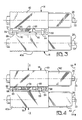
- FIG. 3 is a top view of the interconnected housings in an uncompressed state.
- FIG. 4 is a top view of the housings in a uniformly compressed state illustrating a first form of relative motion between the interconnected housings.
- FIG. 5 is a top view of the housings in a pivotally compressed state illustrating a second from of relative motion between the interconnected housings.
- FIG. 7 is another end view of the housings showing one of the housings twisted illustrating a forth form of relative motion between the interconnected housings.
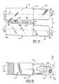
- FIG. 8 is a side view of the housings showing one of the angularly offset illustrating a fifth form of motion between the interconnected housings.
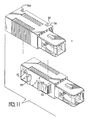
- FIG. 9 is a perspective view of an alternative embodiment of the invention.
- FIG. 10 is a perspective view of a first housing having a retention member and a rear bumper united with a second housing.
- FIG. 11 is a perspective view of a first housing having a retention member separate from a second housing having a clasp member.
- FIG. 12 is a side elevational view of a first housing with a rear bumper united with a second housing.
- FIG. 1 shows a plug assembly 10 from a simplex fiber optic connector (not shown) that is attached to a fiber optic cable 12.
- These plug assemblies 10 fit within their respective housings, a first housing 14 and a second housing 16, which when interconnected holds the plug assemblies 10 in a side-by-side relation with float therebetween in a duplex-like connector 2.
- the float enables easy insertion and removal of the plug assemblies 10 from a receptacle housing 20 as a single unit.
- the receptacle housing 20 has a pair of integrally molded ports 22, each of which contains a sleeve 24 for aligning a ferrule 26 of the plug assembly 10, and an optical fiber 28 therein, with another fiber optic device (not shown).
- plug assemblies 10 are representative of an SC-type optical fiber connector available from the NTT (Nippon Telegraph and Telephone) International Corporation, Tokyo, Japan. While this is a push-pull type of connector, plug assemblies from other types of connectors may also be used.
- the plug assembly 10 has a casing 30 that contains the ferrule 26 which extends from the front of the casing 30.
- the ferrule 26 has the optical fiber 28 from the fiber optic cable 12 contained therein and held coexistent with the face 32 of the ferrule 26.
- the ferrule 26 is adapted for limited linear movement along a longitudinal axis 33 and is biased forward by a spring (not shown) within the casing 30.
- the longitudinal axis 33 of this ferrule 26 is the same as that of the optical fiber 28.
- the casing 30 includes a pair of ribs 34 and a pair of raised pedestals 36 symmetrically located on opposite sides of the casings 30 that, in conjunction with the housing 14,16, as described below, capture the plug assembly 10.
- the fiber optic cable 12 is attached to the plug assembly 10 at the rear of the casing 30 in a conventional manner that isolates the optical fiber 28 from any external shocks.
- a strain relief boot 38 surrounds the fiber optic cable 12 and is attached to the rear of the plug assembly 10 to prevent overbending of the optical fiber 28 as it enters the plug assembly 10.
- Each of the housings 14,16 has a body 40, 40a and a nose 42 with a chamber 44 extending longitudinally therethrough. This chamber 44 is adapted to receive and retainably position the plug assembly 10 so that the ferrule 26 extends forwardly of the nose 42 (FIG. 2).
- the nose 42 has a rectangular tubular configuration with a pair of notched openings 48 extending through opposing sides. Each opening 48 has a front edge 50 and a rear edge 52 that interfere with the ribs 34 and the raised pedestals 36 respectively to prevent the plug assembly 10 from being dislodged from the chamber 44, while still permitting some axial displacement of the plug assembly 10 within the housings 14,16.
- a key 54 is incorporated onto the nose 42 ninety (90) degrees from the openings 48. The configuration of the key 54 may be altered to insure proper mating with a corresponding slot 55 of the receptacle housing 20.
- a pair of beveled lead-in surfaces 56 with corresponding following surfaces 58 therebehind At the front of the nose 42, on each side corresponding to the openings 48, is a pair of beveled lead-in surfaces 56 with corresponding following surfaces 58 therebehind.
- a channel 60 extends from the front of the nose 42, through these surfaces 56,58, to the opening 48.
- the beveled surfaces 56,58 and the channel 60 interact with corresponding resilient fingers 62, having catches 64 thereupon, to enable the catches 64 to pass over and then engage the ribs 34 of the plug assembly 10. Once engaged, the catches 64 ensure that the housings 14,16 and the plug assembly 10 with the optical fiber 28 therein, are retained within the port 22 of the receptacle housing 20.
- each housing 14,16 is integrally formed with the respective nose 42. While this illustrates one possible configuration, it is also possible to have the nose be separate from the housing. Alternatively, the housings 14,16 may be adapted so that the plug assemblies 10 may be accepted having the nose 42 as part of the plug assembly 10 as opposed to being part of the housings 14,16.
- the body 40,40a is an elongate tubular member with a generally rectangular cross-section. The body 40,40a may be gripped to insert and remove the plug assemblies 10 from the receptacle housing 20 as a single unit. The outer surface of the body may have grip enhancing features, such as ribs 41, or some other roughened surface, disposed thereupon.
- the first housing 14 has a retention member 66 on the body 40.
- the retention member 66 is a rectangular retention plate 68 that is generally parallel to one of the sides 69 of the body 40 and offset therefrom by a central post 70.
- An adjacent side of the body is extended outward to the edge of the retention plate 68, forming a base 72 therebetween (best seen in FIG. 1).
- These cavities 74 are separated by the central post 70 that extends between the body 40 and the retention plate 68 from the base 72 across most of the width of the retention plate 68.
- Windows 76 extend through the retention plate 68 and into each of the cavities 74.
- the second housing 16 has a clasp member 78 thereon.
- the clasp member 78 is interconnectable with the retention member 66 to hold the first housing 14 and the second housing 16 in a side-by-side relationship with float therebetween.
- the float is a clearance between the clasp member and the retention member. Relative movement between the first and second housings is bounded by the retention member interfering with the clasp member.
- the clasp member 78 is a pair of resilient arms 82 that extend towards each other in a cantilevered manner from pedestals 84 located at opposite ends of the body 40a.
- Each resilient arm 82 includes a foot 86 opposite the pedestal 84.
- These feet 86 extend away from the body 40a of the second housing 16 and are spaced apart from each other to define a receiving region 88 that is further bounded by the resilient arms 82, the pedestals 84 and the side 80 of the body 40a. Extending into the receiving region 88 from along each of the resilient arms 82 is a detent 90.
- the detent 90 is configured to be received within the window 76 of the retention plate 68 when the clasp member 78 engages the retention member 66 to prevent the housings 14,16 from disengaging.
- the housings 14,16 are interconnected by placing the second housing 16 alongside and slightly above the first housing 14 so that the resilient arms 82 of the second housing 16 are receivable within the U-shaped cavities 74 of the first housing 14. In this position the retention plate 68 and the central post 70 of the first housing 14 are also positioned to correspond to the receiving region 88 of the second housing 16.
- the cam surfaces 92 on the detents 90 come into contact with the retention plate 68, thereby deforming either the resilient arms 82, the retention plate 68 or both so that the detents 90 slide along the retention plate 68 down to the windows 76 where they are received and captivated therein to lock the housings 14,16 together.
- An aspect of this invention is that the housings may remain separate from each other, or be separated from each other, to enable the housings and plug assemblies to be utilized as two simplex connectors.
- This embodiment of the invention makes this particularly attractive as there are no excess parts that might become lost when the housings are separate from each other. This is an especially useful feature where it would be advantageous to temporarily connect one optical fiber into a receptacle housing before the other is connected.
- duplex-like connector it would also be possible to interconnect a greater number of plug assemblies into a string or a block by incorporating multiple clasp members, retention members or some combination thereof into the other sides of one of the housings 14,16. This string or block could then be thought of as a number of interconnected duplex-like connectors.
- the feet 86 of the resilient arms 82 fit generally against the side 69 of the body 40 of the first housing 14, although some looseness is acceptable (FIG. 3).
- the distance the feet 86 extend away from the resilient arms 82 is selected so that the detents 90 are prevented from disengaging from the windows 76 as the housings 14,16 float relative to each other.
- the feet 86 also act to stabilize the housings 14,16 relative to each other by contacting the body 40 of the first housing 14 in two places through which the resiliency of the cantilevered arms 82 exerting a biasing force between the housings 14,16.
- the thickness of the retention plate 68 is selected so that when the feet 86 are against the body 40 of the first housing 14, the retention plate 68 is separated from the second housing 16 by a distance that is sufficient to accommodate any anticipated misalignment due to manufacturing tolerances.
- this uncompressed state shown in FIG. 3
- the housings 14,16 are essentially at their extreme displacement from each other. It would also be possible to have the uncompressed state correspond to the nominal spacing where the housings 14,16 would be compressed or separated in order to accommodate any misalignment to mate with the receptacle housing 20. As seen in FIG.
- the noses 42 of the housings 14,16 may be pivoted towards each other or away from each other (Arrows B in FIG. 5) as the resilient arms are independent of each other. This will deform one of the resilient arms 82. Excessive nose-in orientation is prevented by a forward bumper 98 extending outward from the body 40 of the first housing 14 near the nose 42 from the same side 69 as the retention plate 68.
- the forward bumper 98 comes in contact with the body 40a of the second housing 16 to prevent excessive axial misalignment which might preclude the ferrule 26 from being received within the mating sleeve 24. In addition, this forward bumper 98 prevents over-stressing of the rearward resilient arm 82.
- a rearward bumper 98a similarly prevents excessive nose out orientation.
- the rearward bumper 98a extends outward from the body 40 of the first housing 14 on an end opposite the forward bumper 98 with the retention plate 68 therebetween. As the noses 42 pivot away from each other, the rearward bumper 98a engages the body 40a of the second housing 16 thereby preventing further pivoting. Limiting excessive nose out orientation prevents wedging of the noses 42 into their corresponding receptacles.
- the window 76 in the retention plate 68 that receives the detent 90 is elongated vertically relative to the size of the detent 90, thereby enabling the detent 90 to move therein (FIG. 6).
- the movement of the detent within the window 90 permits the first housing 14 and the second housing 16 to float translationally along a second axis 100 that is perpendicular to both the first axis 94 and the longitudinal axis 96 of the ferrule 26 (shown as Arrows C in FIG. 6).
- the float along the second axis 100 may be limited either by having the resilient arms 82 interfere with the base 72 or by having the detent 90 contact the edges of the window 76.
- the interconnection of the clasp member 78 and the retention member 66 also provides the housings 14,16 and the plug assemblies 10 therein with limited rotational float about the longitudinal axis 33 by way of the resilient arms 82.
- the resilient arm 82 will twist slightly or the feet 86 will become partially disengaged from against the body 14.
- the noses 42 of the housings 14,16 may also be pivoted up and down to accommodate any angular misalignment of the longitudinal axis 33 along the second axis 100 (shown as Arrows E in FIG. 8).
- the portion of the receiving region 88 between the feet 86 of the two resilient arms 82 and the length of the retention plate 68 are sized to closely correspond to the width of the central post 70 and the spacing between the two pedestals 84 respectively (best seen in FIG. 3). This prevents linear displacement of the housings 14,16 along the longitudinal axes 33 maintaining structural rigidity between the two housings 14,16 to enable handling of the housings 14,16 as a pair. Any misalignment along these axes 33 is accommodated by the float inherent in the spring loaded ferrule 26. While float of the interconnection is discussed above primarily with reference to the housings 14,16, it should be noted that it is the alignment of the plug assemblies 10 and the ferrules 26 that are contained within the housings that is of principle importance.
- FIG. 9 shows an alternative embodiment of the invention.
- the windows 76 have been removed from the retention plate 68 and the detents 90 have been removed from the clasp member 78.
- the detents 106 are on resilient fingers 102 at the end of the retention plate 68. These fingers 102 are formed by slicing partially across the retention plate 68 into the corresponding cavity 74.
- the clasp member 78 is engaged as described above and prevented from disengaging by the detents 106 which overlie the clasp member 78.
- the clasp member 78 functioned to both hold the housings 14,16 together and exert a biasing force therebetween to stabilize the housings 14,16 due to the resiliency of the arms 82. It would be possible to bifurcate those functions into two separate elements.
- the retention member 66 could be an elongate T-shaped member or a pair of headed posts and the clasp member 78 could have corresponding key-shaped slot or slots to loosely receive the retention member 66 to hold the housings together and provide the desired float.
- the biasing force between the two housings 14,16 could be exerted by separate elements such as spring arms.
- the clasp member 78 and the retention member 66 do not have moving parts, instead relying on manipulation of the housings 14,16 to effect the interconnection, it may be desirable to have a clasp member 78 or some part thereof that is separably movable relative its housing 16 to engage the retention member 66 or vice versa.
- the retention member 66 and the clasp member 78 are shown in the drawings as integral components of the first housing 14 and the second housing 16 respectively.
- the housings 14,16 including their respective clasp member and retention member, may be economically molded from a commercially available engineering thermoplastic, for example polyester.
- a specific example of an acceptable material being VALOX DR-48 of General Electric Plastics in Pittsfield, Massachusetts. Other materials and manufacturing techniques may also be appropriate depending on the physical manifestation of the invention.
- either the retention member 66, the clasp member 78 or parts thereof may be separately manufactured and then incorporated into their respective housing 14,16. This may be desirable where the clasp member 78 engages the retention member 66 to provide the float for the housings 14,16 and separate members are used to exert a biasing force between the housings.
- the present invention has significant advantages for connecting the plug assemblies of fiber optic connectors in a side-by-side relationship to form a duplex-like connector with float between the plug assemblies. It should be recognized that the above described embodiments, and suggested alternatives, constitute only the presently preferred form of the invention and that the invention may take on numerous other forms, only some of which have been expressly described above. Accordingly, the invention should be only limited by the scope of the following claims.
- Apparatus holds plug assemblies for optical fiber connectors in a side-by-side relationship with float therebetween.
- the float between the housings occurs independently along two axes that are perpendicular to each other and perpendicular to the longitudinal axis of a ferrule within the plug assembly.
Landscapes
- Physics & Mathematics (AREA)
- General Physics & Mathematics (AREA)
- Optics & Photonics (AREA)
- Mechanical Coupling Of Light Guides (AREA)
- Optical Couplings Of Light Guides (AREA)
Claims (9)
- Vorrichtung für das Miteinanderverbinden von Steckeranordnungen von Lichtleiterverbindern Seite an Seite, die aufweist: ein erstes Gehäuse (14) und ein zweites Gehäuse (16), wobei jedes erste (14) und zweite (16) Gehäuse eine Kammer (44) für das hemmende Aufnehmen einer der entsprechenden Steckeranordnungen (10) aufweist, und wobei das erste (14) und zweite (16) Gehäuse beweglich miteinander verbunden werden, dadurch gekennzeichnet, daß das erste Gehäuse (14) ein Halteelement (66) und das zweite Gehäuse (16) ein Hakenelement (78) aufweist, worin das Halteelement (66) angeordnet wird, um lose durch das Hakenelement (78) in Eingriff zu kommen, um die Gehäuse Seite an Seite zu halten, wodurch sich das erste und zweite Gehäuse (14, 16) relativ zueinander bewegen können.
- Vorrichtung nach Anspruch 1, bei der das Halteelement (66) eine Halteplatte (68) ist, die am ersten Gehäuse (14) befestigt und dazu versetzt ist, und bei der das Hakenelement (78) ein Paar elastische Arme (82) aufweist, die sich vom zweiten Gehäuse (16) aus erstrecken und die Halteplatte (68) umschließen.
- Vorrichtung nach Anspruch 2, bei der die Halteplatte (68) ein Fenster (76) umfaßt, und bei der mindestens einer der elastischen Arme (82) eine Einrasteinrichtung (90) umfaßt, die hemmend innerhalb des Fensters (76) aufgenommen wird, wenn das erste (14) und zweite (16) Gehäuse miteinander verbunden werden.
- Vorrichtung nach Anspruch 2, bei der die Halteplatte (68) eine Einrasteinrichtung umfaßt, die verhindert, daß die elastischen Arme (82) von der Halteplatte (68) getrennt werden.
- Vorrichtung nach Anspruch 1, 2, 3 oder 4, bei der das Halteelement (66) mit dem ersten Gehäuse (14) in einem Stück gebildet wird.
- Vorrichtung nach Anspruch 1, 2, 3, 4 oder 5, bei der das Hakenelement (78) mit dem zweiten Gehäuse (16) in einem Stück gebildet wird.
- Vorrichtung nach Anspruch 1, 2, 3, 4, 5 oder 6, bei der mindestens eines von erstem (14) und zweitem (16) Gehäuse ein charakteristisches Merkmal (41) zur Verbesserung der Griffigkeit aufweist.
- Vorrichtung nach einem der Ansprüche 1 bis 7, bei der mindestens eines von erstem (14) und zweitem (16) Gehäuse darauf einen vorderen Puffer (98) aufweist.
- Vorrichtung nach einem der Ansprüche 1 bis 8, bei der mindestens eines von erstem (14) und zweitem (16) Gehäuse darauf einen hinteren Puffer (98a) aufweist.
Applications Claiming Priority (4)
| Application Number | Priority Date | Filing Date | Title |
|---|---|---|---|
| US12722093A | 1993-09-27 | 1993-09-27 | |
| US127220 | 1993-09-27 | ||
| US227933 | 1994-04-15 | ||
| US08/227,933 US5386487A (en) | 1993-09-27 | 1994-04-15 | Apparatus for maintaining plug assemblies of optical fiber connectors in a side by side relation with float therebetween |
Publications (2)
| Publication Number | Publication Date |
|---|---|
| EP0647865A1 EP0647865A1 (de) | 1995-04-12 |
| EP0647865B1 true EP0647865B1 (de) | 1998-07-29 |
Family
ID=26825451
Family Applications (1)
| Application Number | Title | Priority Date | Filing Date |
|---|---|---|---|
| EP94114744A Expired - Lifetime EP0647865B1 (de) | 1993-09-27 | 1994-09-19 | Vorrichtung um optische Stecker mit ihren Seiten beweglich aneinander zu befestigen |
Country Status (8)
| Country | Link |
|---|---|
| US (1) | US5386487A (de) |
| EP (1) | EP0647865B1 (de) |
| JP (1) | JP3505237B2 (de) |
| KR (1) | KR950009288A (de) |
| CN (1) | CN1038617C (de) |
| BR (1) | BR9403832A (de) |
| CA (1) | CA2130043C (de) |
| DE (1) | DE69412024T2 (de) |
Families Citing this family (47)
| Publication number | Priority date | Publication date | Assignee | Title |
|---|---|---|---|---|
| CH690867A5 (de) * | 1994-12-23 | 2001-02-15 | Diamond Sa | Steckergehäuse für ein optisches Steckerpaar. |
| US5553180A (en) * | 1995-01-17 | 1996-09-03 | Molex Incorporated | Adapter assembly for fiber optic connectors |
| US5528712A (en) * | 1995-02-06 | 1996-06-18 | Belenkiy; Yuriy | Duplex connector |
| US5579425A (en) * | 1995-08-30 | 1996-11-26 | Lucent Technologies Inc. | Anti-snag duplex connector |
| USD383380S (en) * | 1996-02-05 | 1997-09-09 | Augat Inc. | Duplex clip and holder |
| DE19608500A1 (de) * | 1996-03-05 | 1997-09-11 | Whitaker Corp | Modular aufgebauter Stecker |
| JP3099113B2 (ja) * | 1996-11-13 | 2000-10-16 | モレックス インコーポレーテッド | 光ファイバプラグ及び光コネクタ |
| US5859766A (en) * | 1997-02-28 | 1999-01-12 | The Whitaker Corporation | Electrical housing for circuit board assembly |
| US5920459A (en) * | 1997-02-04 | 1999-07-06 | The Whitaker Corporation | Electrical connector housing for circuit board assembly |
| US6062738A (en) * | 1997-06-13 | 2000-05-16 | International Business Machines Corporation | Data communications apparatus having improved shielding structure |
| US5951152A (en) * | 1997-06-17 | 1999-09-14 | Lumex, Inc. | Light source housing apparatus and method of manufacture |
| US5987203A (en) * | 1997-10-09 | 1999-11-16 | Lucent Technologies Inc. | Distribution module for optical couplings |
| US6130977A (en) * | 1998-07-17 | 2000-10-10 | Siecor Operations, Llc | Fiber optic connector sleeve having positioning ribs |
| US6267514B1 (en) * | 1998-10-15 | 2001-07-31 | Molex Incorporated | Duplex fiber optic connector system and method of fabrication |
| US6240228B1 (en) * | 1998-10-15 | 2001-05-29 | Molex Incorporated | Duplex fiber optic connector system and method of fabrication |
| US6498880B1 (en) | 1999-03-31 | 2002-12-24 | Picolight Incorporated | Fiber optic ferrule |
| US6409392B1 (en) | 1999-10-19 | 2002-06-25 | Fitel Usa Corp. | Duplex clip for clipping two optical fiber simplex connectors together to form a duplex connector |
| US6290400B1 (en) | 2000-01-04 | 2001-09-18 | International Business Machines Corporation | Self-healing optical backplane for coupling components |
| EP1338909B1 (de) * | 2000-07-03 | 2007-03-28 | Yazaki Corporation | Optischer und hybrider Stecker |
| US6443627B1 (en) | 2001-01-10 | 2002-09-03 | Fitel Usa Corp. | Duplex optical connector |
| US6478472B1 (en) | 2001-01-10 | 2002-11-12 | Fitel Usa Corp. | High-density optical connecting block |
| DE10114144C2 (de) * | 2001-03-16 | 2003-11-06 | Infineon Technologies Ag | Haltevorrichtung zum Halten mindestens eines optischen Steckers |
| US6761488B2 (en) | 2001-04-30 | 2004-07-13 | Infineon Technologies Ag | Holding device for holding at least one optical plug |
| US7016135B2 (en) * | 2001-07-03 | 2006-03-21 | International Business Machines Corporation | Apparatus and method for automated interconnection and disconnection of disk drive carrier in a system |
| US6957351B2 (en) * | 2001-07-03 | 2005-10-18 | International Business Machines Corporation | Automated disk drive library with removable media powered via contactless coupling |
| DE10228008A1 (de) * | 2002-06-22 | 2004-01-15 | Leopold Kostal Gmbh & Co Kg | Zweipoliger optischer Steckverbinder |
| TW563822U (en) * | 2002-08-16 | 2003-11-21 | Hon Hai Prec Ind Co Ltd | Duplex fiber optical connector system |
| US7011454B2 (en) * | 2003-08-25 | 2006-03-14 | Panduit Corp. | Reversible fiber optic stub fiber connector |
| US6905354B1 (en) * | 2003-12-10 | 2005-06-14 | Intel Corporation | U-clip for optical device alignment |
| US20050281509A1 (en) * | 2004-06-18 | 2005-12-22 | 3M Innovative Properties Company | Optical connector system with EMI shielding |
| JP4768384B2 (ja) * | 2005-09-29 | 2011-09-07 | 株式会社東芝 | 光伝送路保持部材及び光モジュール |
| US8167638B2 (en) | 2007-06-12 | 2012-05-01 | Panduit Corp. | Multi-position quick release plug cassette assembly |
| US7972067B2 (en) * | 2009-06-30 | 2011-07-05 | Tyco Electronics Corporation | Fiber optic connector assembly |
| US7794155B1 (en) * | 2009-06-30 | 2010-09-14 | Tyco Electronics Corporation | Fiber optic connector system |
| WO2012172532A2 (en) * | 2011-06-16 | 2012-12-20 | Firecomms Limited | An optical fibre connector |
| US9291782B2 (en) * | 2011-07-01 | 2016-03-22 | Methode Electronics, Inc. | Multi-channel tranceiver module |
| US9829642B2 (en) * | 2013-10-18 | 2017-11-28 | CommScope Connectivity Belgium BVBA | Mounting system for telecommunications distribution elements |
| CN104682072A (zh) * | 2013-11-28 | 2015-06-03 | 鸿富锦精密工业(武汉)有限公司 | 连接器 |
| WO2016048374A1 (en) | 2014-09-26 | 2016-03-31 | Hewlett Packard Enterprise Development Lp | Receptacle for connecting a multi-lane or one-lane cable |
| WO2016133499A1 (en) | 2015-02-18 | 2016-08-25 | Hewlett Packard Enterprise Development Lp | Pull-tabs for disengaging a cable assembly from a receptacle |
| WO2016137486A1 (en) * | 2015-02-27 | 2016-09-01 | Hewlett Packard Enterprise Development Lp | Features to conjoin one-lane cable assemblies |
| US10741963B2 (en) * | 2015-02-27 | 2020-08-11 | Hewlett Packard Enterprise Development Lp | Cable assembly with conjoined one-lane cable assemblies |
| US10389068B2 (en) | 2015-04-29 | 2019-08-20 | Hewlett Packard Enterprise Development Lp | Multiple cable housing assembly |
| GB2538089B (en) * | 2015-05-06 | 2019-06-19 | Fibrefab Ltd | Fibre optic cable assembly |
| CN109411943A (zh) * | 2017-08-17 | 2019-03-01 | 富士康(昆山)电脑接插件有限公司 | 插头连接器模组 |
| WO2021084839A1 (ja) * | 2019-10-31 | 2021-05-06 | 株式会社フジクラ | 清掃工具 |
| US11747576B2 (en) * | 2020-12-29 | 2023-09-05 | Senko Advanced Components, Inc | Clip for holding fiber optic connectors |
Family Cites Families (9)
| Publication number | Priority date | Publication date | Assignee | Title |
|---|---|---|---|---|
| DE3580976D1 (de) * | 1984-06-08 | 1991-01-31 | Amp Inc | Faseroptische hochpraezisionsverbinder. |
| US5076656A (en) * | 1984-06-08 | 1991-12-31 | Briggs Robert C | High precision optical fiber connectors |
| US4953929A (en) * | 1989-07-21 | 1990-09-04 | International Business Machines | Fiber optic connector assembly and adapter for use therewith |
| US4986762A (en) * | 1989-08-15 | 1991-01-22 | Minnesota Mining And Manufacturing Company | Termination module for use in an array of modules |
| US5121454A (en) * | 1989-11-24 | 1992-06-09 | Nippon Telegraph And Telephone Corporation | Optical connector |
| US5123071A (en) * | 1990-03-09 | 1992-06-16 | Amp Incorporated | Overconnector assembly for a pair of push-pull coupling type optical fiber connectors |
| US5222168A (en) * | 1990-12-13 | 1993-06-22 | The Furukawa Electric Co., Ltd. | Method for stacking ferrules of a stacked-type optical connector and a stacked-type optical connector |
| US5325454A (en) * | 1992-11-13 | 1994-06-28 | International Business Machines, Corporation | Fiber optic connector housing |
| US5293581A (en) * | 1993-04-16 | 1994-03-08 | Alcoa Fujikura Ltd. | Flexible connector assembly for fiber optics |
-
1994
- 1994-04-15 US US08/227,933 patent/US5386487A/en not_active Expired - Lifetime
- 1994-08-12 CA CA002130043A patent/CA2130043C/en not_active Expired - Fee Related
- 1994-09-15 CN CN94116123A patent/CN1038617C/zh not_active Expired - Fee Related
- 1994-09-16 KR KR1019940023520A patent/KR950009288A/ko active IP Right Grant
- 1994-09-19 EP EP94114744A patent/EP0647865B1/de not_active Expired - Lifetime
- 1994-09-19 DE DE69412024T patent/DE69412024T2/de not_active Expired - Lifetime
- 1994-09-23 BR BR9403832A patent/BR9403832A/pt not_active Application Discontinuation
- 1994-09-27 JP JP25753494A patent/JP3505237B2/ja not_active Expired - Fee Related
Also Published As
| Publication number | Publication date |
|---|---|
| CN1120676A (zh) | 1996-04-17 |
| US5386487A (en) | 1995-01-31 |
| CA2130043C (en) | 1998-08-04 |
| EP0647865A1 (de) | 1995-04-12 |
| KR950009288A (ko) | 1995-04-21 |
| DE69412024D1 (de) | 1998-09-03 |
| DE69412024T2 (de) | 1999-01-21 |
| CA2130043A1 (en) | 1995-03-28 |
| BR9403832A (pt) | 1995-05-30 |
| CN1038617C (zh) | 1998-06-03 |
| JPH07159653A (ja) | 1995-06-23 |
| JP3505237B2 (ja) | 2004-03-08 |
Similar Documents
| Publication | Publication Date | Title |
|---|---|---|
| EP0647865B1 (de) | Vorrichtung um optische Stecker mit ihren Seiten beweglich aneinander zu befestigen | |
| KR100308629B1 (ko) | 광 섬유 커넥터 조립체 | |
| US4872736A (en) | Connector assembly having a latching mechanism | |
| EP0582675B1 (de) | Steckverbinder für lichtwellenleiter | |
| EP0156397B1 (de) | Fiberoptischer Stecker | |
| US6634796B2 (en) | Polarity reversal for fiber optic connections | |
| US5619604A (en) | Multi-fiber optical connector | |
| US5268982A (en) | Friction detent duplex plug assembly | |
| CA2179833C (en) | Anti-snag duplex connector | |
| EP2035874B1 (de) | Optischer stecker | |
| US5971626A (en) | Fiber optic connector and connector sleeve assembly | |
| US6095695A (en) | Optical connector, and using method and tool thereof | |
| EP1074869A1 (de) | Plastischoptischer Faser Stecker | |
| US4445750A (en) | Articulating fiber optic connectors with resilient mounting block | |
| US20150177463A1 (en) | Optical fiber connector assembly | |
| EP0213672A2 (de) | Vielfachfaser optischer Kabelstecker | |
| EP0597501A1 (de) | Gehäuse für faseroptische Stecker | |
| US11592626B2 (en) | Fiber optic connector with boot-integrated release and related assemblies | |
| US20080131055A1 (en) | Keyed push-pull type fiber optic connection system | |
| WO2002008805A3 (en) | Fiber optic coupler with in-line optical component | |
| EP0730174B1 (de) | Duplex-Verbinder | |
| US20200174198A1 (en) | Fiber optic connector with unitary housing and fiber optic connector assembly | |
| US6688782B1 (en) | Universal ferrule | |
| WO2006029299A2 (en) | Optical connector system including reduced-size mt-style ferrule | |
| EP0076514A2 (de) | Optische Steckverbindung |
Legal Events
| Date | Code | Title | Description |
|---|---|---|---|
| PUAI | Public reference made under article 153(3) epc to a published international application that has entered the european phase |
Free format text: ORIGINAL CODE: 0009012 |
|
| AK | Designated contracting states |
Kind code of ref document: A1 Designated state(s): CH DE FR GB IT LI NL SE |
|
| 17P | Request for examination filed |
Effective date: 19950911 |
|
| GRAG | Despatch of communication of intention to grant |
Free format text: ORIGINAL CODE: EPIDOS AGRA |
|
| 17Q | First examination report despatched |
Effective date: 19971002 |
|
| GRAG | Despatch of communication of intention to grant |
Free format text: ORIGINAL CODE: EPIDOS AGRA |
|
| GRAH | Despatch of communication of intention to grant a patent |
Free format text: ORIGINAL CODE: EPIDOS IGRA |
|
| GRAH | Despatch of communication of intention to grant a patent |
Free format text: ORIGINAL CODE: EPIDOS IGRA |
|
| GRAA | (expected) grant |
Free format text: ORIGINAL CODE: 0009210 |
|
| AK | Designated contracting states |
Kind code of ref document: B1 Designated state(s): CH DE FR GB IT LI NL SE |
|
| PG25 | Lapsed in a contracting state [announced via postgrant information from national office to epo] |
Ref country code: LI Free format text: LAPSE BECAUSE OF FAILURE TO SUBMIT A TRANSLATION OF THE DESCRIPTION OR TO PAY THE FEE WITHIN THE PRESCRIBED TIME-LIMIT Effective date: 19980729 Ref country code: IT Free format text: LAPSE BECAUSE OF FAILURE TO SUBMIT A TRANSLATION OF THE DESCRIPTION OR TO PAY THE FEE WITHIN THE PRE;WARNING: LAPSES OF ITALIAN PATENTS WITH EFFECTIVE DATE BEFORE 2007 MAY HAVE OCCURRED AT ANY TIME BEFORE 2007. THE CORRECT EFFECTIVE DATE MAY BE DIFFERENT FROM THE ONE RECORDED.SCRIBED TIME-LIMIT Effective date: 19980729 Ref country code: CH Free format text: LAPSE BECAUSE OF FAILURE TO SUBMIT A TRANSLATION OF THE DESCRIPTION OR TO PAY THE FEE WITHIN THE PRESCRIBED TIME-LIMIT Effective date: 19980729 |
|
| RIN1 | Information on inventor provided before grant (corrected) |
Inventor name: MANNING, RANDY MARSHALL Inventor name: FAWCETT, THOMAS RALPH, JR. Inventor name: BRIGGS, ROBERT CARL |
|
| REG | Reference to a national code |
Ref country code: CH Ref legal event code: EP |
|
| REF | Corresponds to: |
Ref document number: 69412024 Country of ref document: DE Date of ref document: 19980903 |
|
| ET | Fr: translation filed | ||
| PG25 | Lapsed in a contracting state [announced via postgrant information from national office to epo] |
Ref country code: SE Free format text: LAPSE BECAUSE OF FAILURE TO SUBMIT A TRANSLATION OF THE DESCRIPTION OR TO PAY THE FEE WITHIN THE PRESCRIBED TIME-LIMIT Effective date: 19981029 |
|
| REG | Reference to a national code |
Ref country code: CH Ref legal event code: PL |
|
| PLBE | No opposition filed within time limit |
Free format text: ORIGINAL CODE: 0009261 |
|
| STAA | Information on the status of an ep patent application or granted ep patent |
Free format text: STATUS: NO OPPOSITION FILED WITHIN TIME LIMIT |
|
| 26N | No opposition filed | ||
| REG | Reference to a national code |
Ref country code: GB Ref legal event code: IF02 |
|
| PGFP | Annual fee paid to national office [announced via postgrant information from national office to epo] |
Ref country code: NL Payment date: 20090924 Year of fee payment: 16 Ref country code: GB Payment date: 20090929 Year of fee payment: 16 |
|
| PGFP | Annual fee paid to national office [announced via postgrant information from national office to epo] |
Ref country code: DE Payment date: 20090929 Year of fee payment: 16 |
|
| REG | Reference to a national code |
Ref country code: NL Ref legal event code: V1 Effective date: 20110401 |
|
| GBPC | Gb: european patent ceased through non-payment of renewal fee |
Effective date: 20100919 |
|
| REG | Reference to a national code |
Ref country code: FR Ref legal event code: ST Effective date: 20110531 |
|
| REG | Reference to a national code |
Ref country code: DE Ref legal event code: R119 Ref document number: 69412024 Country of ref document: DE Effective date: 20110401 |
|
| PG25 | Lapsed in a contracting state [announced via postgrant information from national office to epo] |
Ref country code: DE Free format text: LAPSE BECAUSE OF NON-PAYMENT OF DUE FEES Effective date: 20110401 Ref country code: FR Free format text: LAPSE BECAUSE OF NON-PAYMENT OF DUE FEES Effective date: 20100930 |
|
| PG25 | Lapsed in a contracting state [announced via postgrant information from national office to epo] |
Ref country code: GB Free format text: LAPSE BECAUSE OF NON-PAYMENT OF DUE FEES Effective date: 20100919 Ref country code: NL Free format text: LAPSE BECAUSE OF NON-PAYMENT OF DUE FEES Effective date: 20110401 |
|
| PGFP | Annual fee paid to national office [announced via postgrant information from national office to epo] |
Ref country code: FR Payment date: 20091006 Year of fee payment: 16 |