EP0647480B1 - Verfahren zum Ausscheiden von Mehrwegflaschen aus dem Mehrwegumlauf - Google Patents
Verfahren zum Ausscheiden von Mehrwegflaschen aus dem Mehrwegumlauf Download PDFInfo
- Publication number
- EP0647480B1 EP0647480B1 EP94112756A EP94112756A EP0647480B1 EP 0647480 B1 EP0647480 B1 EP 0647480B1 EP 94112756 A EP94112756 A EP 94112756A EP 94112756 A EP94112756 A EP 94112756A EP 0647480 B1 EP0647480 B1 EP 0647480B1
- Authority
- EP
- European Patent Office
- Prior art keywords
- bottle
- distance
- bottles
- signal
- circulation
- Prior art date
- Legal status (The legal status is an assumption and is not a legal conclusion. Google has not performed a legal analysis and makes no representation as to the accuracy of the status listed.)
- Expired - Lifetime
Links
Images


Classifications
-
- G—PHYSICS
- G01—MEASURING; TESTING
- G01N—INVESTIGATING OR ANALYSING MATERIALS BY DETERMINING THEIR CHEMICAL OR PHYSICAL PROPERTIES
- G01N21/00—Investigating or analysing materials by the use of optical means, i.e. using sub-millimetre waves, infrared, visible or ultraviolet light
- G01N21/84—Systems specially adapted for particular applications
- G01N21/88—Investigating the presence of flaws or contamination
- G01N21/90—Investigating the presence of flaws or contamination in a container or its contents
- G01N21/9081—Inspection especially designed for plastic containers, e.g. preforms
-
- B—PERFORMING OPERATIONS; TRANSPORTING
- B07—SEPARATING SOLIDS FROM SOLIDS; SORTING
- B07C—POSTAL SORTING; SORTING INDIVIDUAL ARTICLES, OR BULK MATERIAL FIT TO BE SORTED PIECE-MEAL, e.g. BY PICKING
- B07C5/00—Sorting according to a characteristic or feature of the articles or material being sorted, e.g. by control effected by devices which detect or measure such characteristic or feature; Sorting by manually actuated devices, e.g. switches
- B07C5/34—Sorting according to other particular properties
- B07C5/3404—Sorting according to other particular properties according to properties of containers or receptacles, e.g. rigidity, leaks, fill-level
- B07C5/3408—Sorting according to other particular properties according to properties of containers or receptacles, e.g. rigidity, leaks, fill-level for bottles, jars or other glassware
-
- Y—GENERAL TAGGING OF NEW TECHNOLOGICAL DEVELOPMENTS; GENERAL TAGGING OF CROSS-SECTIONAL TECHNOLOGIES SPANNING OVER SEVERAL SECTIONS OF THE IPC; TECHNICAL SUBJECTS COVERED BY FORMER USPC CROSS-REFERENCE ART COLLECTIONS [XRACs] AND DIGESTS
- Y10—TECHNICAL SUBJECTS COVERED BY FORMER USPC
- Y10S—TECHNICAL SUBJECTS COVERED BY FORMER USPC CROSS-REFERENCE ART COLLECTIONS [XRACs] AND DIGESTS
- Y10S209/00—Classifying, separating, and assorting solids
- Y10S209/938—Illuminating means facilitating visual inspection
Definitions
- the invention relates to a method for separating reusable bottles, in particular plastic reusable bottles, from the reusable circulation.
- the invention further relates to a device for performing the method.
- this object is achieved in that, with each bottle return, the bottles conveyed on a bottle conveyor system are each guided past an optical distance measuring device, which strikes the edge region of the bottle bottom with its measuring beam, and in that the distance measurement signal is evaluated and that, depending on the evaluation, the bottle is either eliminated from the reusable circulation or left in it.
- an optical distance measuring device in particular a laser distance measuring device, can be used to obtain a distance measuring signal which, even when the bottles are conveyed rapidly on an industrial conveyor system (e.g. with 600 bottles per minute), provides evaluable information about the quantity and depth of the Contains "stress cracks" so that by evaluating the distance measurement signal, the respective bottle can be eliminated from the reusable circulation or not. This results in a simple and inexpensive way of recognizing the "stress cracks".
- the light intensity of the reflected measuring beam is preferably also included in the evaluation in order to be able to distinguish even better between those bottles which are found to be “good” and those which are found to be “bad".
- FIG. 1 shows the lower area of a PET bottle 1 (in vertical cross section) in a highly schematic form.
- the stand area 2 of the bottle and the dome 3 bulging from the stand area towards the inside of the bottle can be seen.
- the distance measuring device 5 which is, for example, an opto NCDT series 1605 laser distance measuring device from Micro-Epsilon Messtechnik GmbH & Co KG, Ortenburg , Germany, is working according to the known Triangulation measurement principle and is arranged at a distance from the bottle according to the manufacturer's instructions.
- a point of light according to arrow A is projected onto the bottle. This light spot is imaged via a lens 4 on a position sensor in the distance measuring device.
- the position sensor provides a position-dependent analog output voltage that is proportional to the measuring path (distance sensor-bottle bottom).
- the reflected light intensity represents an additional analog output voltage.
- the output voltages are output to an analysis device 6, for example to a computer.
- the bottle 1 is arranged on a conveyor system, not shown, for example a linear conveyor system or a carousel conveyor system, and is moved relative to the distance measuring device.
- the path of the measuring point runs, for example, as indicated schematically in FIG. 2, over the standing area 2 into the inner edge area of the standing area 2 or the outer edge area of the dome 3.
- Distance of the measuring point from the base preferably about 3 to 8 mm, more preferably about 5 to 8 mm.
- the inclination of the distance measuring device to the longitudinal axis of the bottle is preferably approximately 45 degrees.
- another location on the bottle bottom could be checked with another distance measuring device.
- a further path could be provided parallel to and opposite to the path shown, or a path of a further measuring point that runs at an oblique angle to the path shown. It is also possible to leave the measuring point stationary and to rotate the bottle around a vertical axis so that the measuring path runs in a circle. If there are several lanes, they may have different distances from the stand area.
- the width of the cracking ring can also be determined quite accurately with several distance measuring devices. Leaves make a statement about the width of the cracking ring even with only one web as shown in FIG. 2, which is explained below with reference to FIGS. 3a and 3b.
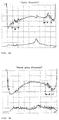
- Figures 3a to 3d each show the output signals of the distance measuring device. All diagrams contain two graphs. The graph at the top shows a measurement signal, which means the distance between the bottle and the distance measuring device. The curve shows a surface panorama of the inner dome at a scanning angle of approximately 45 degrees. The maximum measuring height difference within the dome is about 8 mm. Due to the scanning angle, the dome appears more curved than expected.
- the lower curve shows the amount of light reflected by the measurement object. This signal can be used to improve the informative value of the sensor. This enables the measuring range to be better monitored and the valid signal to be clearly separated from the invalid signal.
- the upper graph shows the relative distance from the sensor to the object.
- the object selected is the point that reflects the most light on the PSD sensor. This means that background suppression should be carried out since the rear wall is also struck by the laser beam.
- This "measurement window” is defined by passing a bottle painted on the floor and storing this signal. Then it will be a measurement range superimposed on this reference signal, which has a programmable bandwidth.
- the measurement signal must then be within this bandwidth. Due to the scatter in the bottle geometry and the position error of the objects during the measurement, the window width must be determined and set once.
- the second signal (lower curve) can now be evaluated using the same procedure.
- This signal corresponds to the amount of light reflected. If this signal is within an adjustable range, the measurement (upper curve) can be recognized as a valid signal. In the area of the center there are reflections with good bottles, which cause a typical peak in the lower curve. In the case of strongly stressed bottles, on the other hand, the lower measured value (amount of light) appears rather as constant. Typical ripples can also be quantified with this signal.
- analog signal preprocessing can be carried out, which highlights some of the effects mentioned.
- the ripple component of both curves can be formed by filtering and processing using RMS-DC converters or deriving the signal (using a differentiator).
- the total reflected light output can be summed up and evaluated with an integrator.
- the actual evaluation can be limited to the punctual comparison of some points of the ascertained graphs with reference values, which is carried out on-line by a computer.
- a limit curve can be specified for both curves above and below, which limit curves form a window for the signal curve. Those points where the signal curve leaves the specified window can then be specially evaluated. It can be determined by suitable evaluation (if necessary several distance measuring devices) determine whether there is a fine, roughened surface (haze) or whether there are many fine cracks or less deep cracks. Radial cracks can also be distinguished from circular cracks. Bottles identified as defective are then removed from the conveying path. The respectively determined graphs can also be compared with pattern curves, for which purpose neural networks or "fuzzy logic" systems are used.
- the width of the cracking ring can be found in dimension d, which is shown in FIGS. 3a and 3b.
Landscapes
- General Health & Medical Sciences (AREA)
- General Physics & Mathematics (AREA)
- Life Sciences & Earth Sciences (AREA)
- Chemical & Material Sciences (AREA)
- Analytical Chemistry (AREA)
- Biochemistry (AREA)
- Immunology (AREA)
- Physics & Mathematics (AREA)
- Health & Medical Sciences (AREA)
- Pathology (AREA)
- Processing Of Solid Wastes (AREA)
- Length Measuring Devices By Optical Means (AREA)
- Processing And Handling Of Plastics And Other Materials For Molding In General (AREA)
- Investigating Materials By The Use Of Optical Means Adapted For Particular Applications (AREA)
Applications Claiming Priority (2)
| Application Number | Priority Date | Filing Date | Title |
|---|---|---|---|
| CH3045/93 | 1993-10-08 | ||
| CH304593 | 1993-10-08 |
Publications (2)
| Publication Number | Publication Date |
|---|---|
| EP0647480A1 EP0647480A1 (de) | 1995-04-12 |
| EP0647480B1 true EP0647480B1 (de) | 1997-10-15 |
Family
ID=4247383
Family Applications (1)
| Application Number | Title | Priority Date | Filing Date |
|---|---|---|---|
| EP94112756A Expired - Lifetime EP0647480B1 (de) | 1993-10-08 | 1994-08-16 | Verfahren zum Ausscheiden von Mehrwegflaschen aus dem Mehrwegumlauf |
Country Status (12)
| Country | Link |
|---|---|
| US (1) | US5730298A (da) |
| EP (1) | EP0647480B1 (da) |
| JP (1) | JPH07159347A (da) |
| CN (1) | CN1104766A (da) |
| AT (1) | ATE159193T1 (da) |
| BR (1) | BR9404029A (da) |
| CA (1) | CA2130950A1 (da) |
| DE (1) | DE59404333D1 (da) |
| DK (1) | DK0647480T3 (da) |
| FI (1) | FI944594A7 (da) |
| NO (1) | NO943797D0 (da) |
| PL (1) | PL305356A1 (da) |
Families Citing this family (7)
| Publication number | Priority date | Publication date | Assignee | Title |
|---|---|---|---|---|
| FR2722574B1 (fr) * | 1994-07-12 | 1996-10-04 | Verreries Souchon Neuvesel Sa | Procede et dispositif pour detecter, par le traitement de sequences d'images, des defauts reflechissant la lumiere et presentes par un objet creux transparent |
| FR2802643B1 (fr) * | 1999-12-15 | 2002-03-08 | Sgcc | Procede de controle de la qualite d'un article notamment en verre |
| US6473170B2 (en) * | 2001-01-19 | 2002-10-29 | White Cap, Inc. | Linear optical sensor for a closure |
| US7010863B1 (en) | 2004-01-26 | 2006-03-14 | Owens-Brockway Glass Container Inc. | Optical inspection apparatus and method for inspecting container lean |
| EP2071368A4 (en) * | 2006-09-15 | 2012-03-28 | Mgc Filsheet Co Ltd | retardation |
| WO2015023673A2 (en) | 2013-08-12 | 2015-02-19 | Agr International, Inc. | Blow molder control systems snad methods |
| BR112022020187A2 (pt) | 2020-04-08 | 2022-11-22 | Coca Cola Co | Sistemas e métodos para monitorar embalagens retornáveis enchidas em uma instalação de engarrafamento |
Family Cites Families (13)
| Publication number | Priority date | Publication date | Assignee | Title |
|---|---|---|---|---|
| JPS5713342A (en) * | 1980-06-27 | 1982-01-23 | Kirin Brewery Co Ltd | Defect detecting system |
| JPS57137844A (en) * | 1981-02-20 | 1982-08-25 | Kirin Brewery Co Ltd | Detector for defect |
| US4591996A (en) * | 1981-05-18 | 1986-05-27 | Vachon Reginald I | Apparatus and method for determining stress and strain in pipes, pressure vessels, structural members and other deformable bodies |
| JPS61278740A (ja) * | 1985-06-04 | 1986-12-09 | Yamamura Glass Kk | 瓶検査装置 |
| US4707610A (en) * | 1985-07-03 | 1987-11-17 | Siscan Systems, Inc. | Method and apparatus for measuring surface profiles |
| DE3611536A1 (de) * | 1986-04-05 | 1987-10-15 | Battelle Institut E V | Vorrichtung zur automatischen ueberpruefung von transparenten objekten, insbesondere von glasflaschen |
| JP2528897B2 (ja) * | 1987-09-10 | 1996-08-28 | 大日本印刷株式会社 | 合成樹脂製容器の変形度測定方法 |
| US4903528A (en) * | 1988-09-26 | 1990-02-27 | Measurex Corporation | System and process for detecting properties of travelling sheets in the cross direction |
| US5127726A (en) * | 1989-05-19 | 1992-07-07 | Eastman Kodak Company | Method and apparatus for low angle, high resolution surface inspection |
| JPH03229113A (ja) * | 1990-02-05 | 1991-10-11 | Fuji Electric Co Ltd | 測距装置 |
| US5233199A (en) * | 1991-07-15 | 1993-08-03 | Fuji Electric Co., Ltd. | Cylindrical container's inner surface tester |
| DE4200971C2 (de) * | 1992-01-16 | 1997-08-07 | Krieg Gunther | Verfahren und Vorrichtung für die Schadstoffdetektion und - identifikation in Getränkeflaschen in Abfüllinien |
| US5405015A (en) * | 1993-08-11 | 1995-04-11 | Videojet Systems International, Inc. | System and method for seeking and presenting an area for reading with a vision system |
-
1994
- 1994-08-16 DK DK94112756.5T patent/DK0647480T3/da active
- 1994-08-16 DE DE59404333T patent/DE59404333D1/de not_active Expired - Fee Related
- 1994-08-16 AT AT94112756T patent/ATE159193T1/de not_active IP Right Cessation
- 1994-08-16 EP EP94112756A patent/EP0647480B1/de not_active Expired - Lifetime
- 1994-08-26 CA CA002130950A patent/CA2130950A1/en not_active Abandoned
- 1994-10-03 FI FI944594A patent/FI944594A7/fi not_active Application Discontinuation
- 1994-10-07 PL PL94305356A patent/PL305356A1/xx unknown
- 1994-10-07 NO NO943797A patent/NO943797D0/no unknown
- 1994-10-07 BR BR9404029A patent/BR9404029A/pt not_active Application Discontinuation
- 1994-10-08 CN CN94116838.7A patent/CN1104766A/zh active Pending
- 1994-10-11 JP JP6245482A patent/JPH07159347A/ja active Pending
-
1996
- 1996-05-03 US US08/642,592 patent/US5730298A/en not_active Expired - Fee Related
Also Published As
| Publication number | Publication date |
|---|---|
| CN1104766A (zh) | 1995-07-05 |
| PL305356A1 (en) | 1995-04-18 |
| DE59404333D1 (de) | 1997-11-20 |
| FI944594L (fi) | 1995-04-09 |
| DK0647480T3 (da) | 1998-04-27 |
| BR9404029A (pt) | 1995-06-13 |
| EP0647480A1 (de) | 1995-04-12 |
| NO943797D0 (no) | 1994-10-07 |
| JPH07159347A (ja) | 1995-06-23 |
| ATE159193T1 (de) | 1997-11-15 |
| US5730298A (en) | 1998-03-24 |
| FI944594A0 (fi) | 1994-10-03 |
| CA2130950A1 (en) | 1995-04-09 |
| FI944594A7 (fi) | 1995-04-09 |
Similar Documents
| Publication | Publication Date | Title |
|---|---|---|
| DE4405376C1 (de) | Verfahren zum Erfassen von Objekten in einem Überwachungsbereich | |
| EP1057727B1 (de) | Verfahren und Vorrichtung zum Prüfen von Zigarettenköpfen | |
| DE10062254C2 (de) | Verfahren und Vorrichtung zum Charakterisieren einer Oberfläche und Verfahren und Vorrichtung zur Ermittlung einer Formanomalie einer Oberfläche | |
| DE10062251C2 (de) | Vorrichtung und Verfahren zur Qualitätsüberprüfung eines Körpers | |
| DE68903400T2 (de) | Vorrichtung und verfahren zum inspizieren der seite eines reifens. | |
| DE19730885A1 (de) | Verfahren zur automatischen Erkennung von Oberflächenfehlern an Rohkarosserien und Vorrichtung zur Durchführung des Verfahrens | |
| EP1431707B1 (de) | Verfahren und Vorrichtung zur Erfassung von auf einem Fördermittel bewegten Objekten mittels eines optoelektronischen Sensors | |
| EP0647480B1 (de) | Verfahren zum Ausscheiden von Mehrwegflaschen aus dem Mehrwegumlauf | |
| DE10006663B4 (de) | Verfahren zur Vermessung von langwelligen Oberflächenstrukturen | |
| DE68921425T2 (de) | Optische Einrichtung für die Prüfung des Endes von Zigaretten. | |
| WO2023084116A1 (de) | Verfahren und vorrichtung zur klassifizierung von objekten, die auf einer oberfläche liegend gefördert werden | |
| EP3323517A1 (de) | Sortiersystem und verfahren zur verfolgung eines einsortierens eines sortierguts in ein sortierregister | |
| DE10063786A1 (de) | Vorrichtung und Verfahren zum Vermessen eines Gegenstandes | |
| DE102008049859B4 (de) | Verfahren und Prüfsystem zur optischen Prüfung einer Kontur eines Prüfobjekts | |
| EP3663796B1 (de) | Verfahren zur bestimmung eines abstands | |
| EP0617256B1 (de) | Verfahren zur Ermittlung eines Durchmessers einer Umfangslinie an Rädern von Radsätzen und Einrichtung zur Durchführung des Verfahrens | |
| EP2216644A2 (de) | Verfahren und Vorrichtung zur Qualitätsprüfung | |
| EP0597178B1 (de) | Verfahren und Vorrichtung zur Identifizierung von Gegenständen | |
| EP4328543B1 (de) | Verfahren zur beurteilung des ergebnisses einer an einem werkstück durch partikelstrahlen durchgeführten oberflächenbehandlung | |
| DE4332022A1 (de) | Verfahren und Vorrichtung zum berührungslosen Erfassen der Winkellage eines Objekts, insbesondere beim Vermessen von länglichen Gegenständen | |
| CH669663A5 (da) | ||
| DE4407285A1 (de) | Verfahren zur Messung der Lage eines Loches | |
| DE102018217530B4 (de) | Einrichtung zur Ermittlung von Positionen oder Trajektorien eines oder mehrerer Partikel | |
| WO2003016819A1 (de) | Verfahren zur vermessung von oberflächenstrukturen | |
| DE10014627A1 (de) | Verfahren und Vorrichtung zum Abbilden von Objekten |
Legal Events
| Date | Code | Title | Description |
|---|---|---|---|
| PUAI | Public reference made under article 153(3) epc to a published international application that has entered the european phase |
Free format text: ORIGINAL CODE: 0009012 |
|
| 17P | Request for examination filed |
Effective date: 19950119 |
|
| AK | Designated contracting states |
Kind code of ref document: A1 Designated state(s): AT BE CH DE DK LI NL SE |
|
| RAP1 | Party data changed (applicant data changed or rights of an application transferred) |
Owner name: ELPATRONIC AG |
|
| GRAG | Despatch of communication of intention to grant |
Free format text: ORIGINAL CODE: EPIDOS AGRA |
|
| GRAH | Despatch of communication of intention to grant a patent |
Free format text: ORIGINAL CODE: EPIDOS IGRA |
|
| 17Q | First examination report despatched |
Effective date: 19970318 |
|
| GRAH | Despatch of communication of intention to grant a patent |
Free format text: ORIGINAL CODE: EPIDOS IGRA |
|
| GRAA | (expected) grant |
Free format text: ORIGINAL CODE: 0009210 |
|
| AK | Designated contracting states |
Kind code of ref document: B1 Designated state(s): AT BE CH DE DK LI NL SE |
|
| REF | Corresponds to: |
Ref document number: 159193 Country of ref document: AT Date of ref document: 19971115 Kind code of ref document: T |
|
| REG | Reference to a national code |
Ref country code: CH Ref legal event code: EP |
|
| REF | Corresponds to: |
Ref document number: 59404333 Country of ref document: DE Date of ref document: 19971120 |
|
| REG | Reference to a national code |
Ref country code: DK Ref legal event code: T3 |
|
| PG25 | Lapsed in a contracting state [announced via postgrant information from national office to epo] |
Ref country code: AT Free format text: LAPSE BECAUSE OF NON-PAYMENT OF DUE FEES Effective date: 19980816 |
|
| PG25 | Lapsed in a contracting state [announced via postgrant information from national office to epo] |
Ref country code: SE Free format text: LAPSE BECAUSE OF NON-PAYMENT OF DUE FEES Effective date: 19980817 |
|
| PLBE | No opposition filed within time limit |
Free format text: ORIGINAL CODE: 0009261 |
|
| STAA | Information on the status of an ep patent application or granted ep patent |
Free format text: STATUS: NO OPPOSITION FILED WITHIN TIME LIMIT |
|
| PG25 | Lapsed in a contracting state [announced via postgrant information from national office to epo] |
Ref country code: LI Free format text: LAPSE BECAUSE OF NON-PAYMENT OF DUE FEES Effective date: 19980831 Ref country code: DK Free format text: LAPSE BECAUSE OF NON-PAYMENT OF DUE FEES Effective date: 19980831 Ref country code: CH Free format text: LAPSE BECAUSE OF NON-PAYMENT OF DUE FEES Effective date: 19980831 Ref country code: BE Free format text: LAPSE BECAUSE OF NON-PAYMENT OF DUE FEES Effective date: 19980831 |
|
| 26N | No opposition filed | ||
| BERE | Be: lapsed |
Owner name: ELPATRONIC A.G. Effective date: 19980831 |
|
| PG25 | Lapsed in a contracting state [announced via postgrant information from national office to epo] |
Ref country code: NL Free format text: LAPSE BECAUSE OF NON-PAYMENT OF DUE FEES Effective date: 19990301 |
|
| REG | Reference to a national code |
Ref country code: CH Ref legal event code: PL |
|
| EUG | Se: european patent has lapsed |
Ref document number: 94112756.5 |
|
| NLV4 | Nl: lapsed or anulled due to non-payment of the annual fee |
Effective date: 19990301 |
|
| PG25 | Lapsed in a contracting state [announced via postgrant information from national office to epo] |
Ref country code: DE Free format text: LAPSE BECAUSE OF NON-PAYMENT OF DUE FEES Effective date: 19990601 |
|
| REG | Reference to a national code |
Ref country code: DK Ref legal event code: EBP |