EP0646532A2 - Storage and transport container - Google Patents
Storage and transport container Download PDFInfo
- Publication number
- EP0646532A2 EP0646532A2 EP94115527A EP94115527A EP0646532A2 EP 0646532 A2 EP0646532 A2 EP 0646532A2 EP 94115527 A EP94115527 A EP 94115527A EP 94115527 A EP94115527 A EP 94115527A EP 0646532 A2 EP0646532 A2 EP 0646532A2
- Authority
- EP
- European Patent Office
- Prior art keywords
- container
- container according
- floor
- floor pan
- cross members
- Prior art date
- Legal status (The legal status is an assumption and is not a legal conclusion. Google has not performed a legal analysis and makes no representation as to the accuracy of the status listed.)
- Granted
Links
Images

Classifications
-
- B—PERFORMING OPERATIONS; TRANSPORTING
- B65—CONVEYING; PACKING; STORING; HANDLING THIN OR FILAMENTARY MATERIAL
- B65D—CONTAINERS FOR STORAGE OR TRANSPORT OF ARTICLES OR MATERIALS, e.g. BAGS, BARRELS, BOTTLES, BOXES, CANS, CARTONS, CRATES, DRUMS, JARS, TANKS, HOPPERS, FORWARDING CONTAINERS; ACCESSORIES, CLOSURES, OR FITTINGS THEREFOR; PACKAGING ELEMENTS; PACKAGES
- B65D90/00—Component parts, details or accessories for large containers
- B65D90/22—Safety features
- B65D90/24—Spillage-retaining means, e.g. recovery ponds
Definitions
- the invention relates to a container for transporting and storing, in particular, combustible and non-combustible water-polluting liquids in the form of a container according to the preamble of claim 1.
- Such a container is known for example from DE-GM 91 03 293. It has the standardized basic shape of a cuboid with four side walls, a roof and a floor pan. In two of the side walls, namely in the end faces, there are closable ventilation openings.
- the floor pan is liquid-tight and covered by a floor grate, which is arranged elevated above the floor pan of the floor pan.
- the bottom grate represents the transport and storage area of the container.
- the bottom pan formed below the bottom grate serves as a collecting pan for inadvertently escaping liquid which is to be transported and stored.
- the liquids are, in particular, flammable or non-flammable water-polluting liquids which are placed in cubic tank containers, large packaging, barrels, canisters, containers or other portable containers.
- the known container it is thus possible to both transport and store such liquids in compliance with relevant regulations.
- the suitability of the container as a warehouse is realized by the closable openings, so that the legally required air exchange inside the container is given.
- the liquid-tight floor pan is designed in such a way that it meets the requirements of the Water Resources Act.
- the invention was therefore based on the problem of designing such a container such that it no longer has the disadvantages described.
- a container should be made available, the bottom assembly of which is sufficiently flat so that it can be used in practice for all conceivable transport and storage tasks.
- the invention is based on the idea of equipping the container in the form of a non-flammable box-type material with a centering tunnel and four retractable support legs, the floor pan being designed in such a way that it directly takes over the load-bearing function of a floor group and at the same time the standardized guide and Support elements of such a swap body can accommodate.
- the floor pan consists of a floor panel profiled in the longitudinal direction, two side longitudinal beams and two end cross members being designed as integral components of the floor pan and all other cross beams required for stability only within the floor pan between the side rails arranged and connected to it. This creates a self-supporting floor assembly that also functions as a floor pan.
- the container is therefore particularly suitable for the international movement of goods and for transport by road as well as by rail. The change between the two transport systems succeeds in the proven way.
- the maximum height of the floor assembly i.e. limit the distance from the lowest point of the container (centering tunnel, fastening fittings or lower edge of the folded support legs) to the upper edge of the container base (bottom grate) to a maximum of 240 mm.
- the floor grate itself can be driven on directly, so that the loading and unloading of the container with such conveyor vehicles can be carried out easily and quickly.
- the existing handling, transport, loading and unloading logistics can be kept unchanged.
- the floor pan is in particular specially designed in the corner areas laterally inward so that there are box-shaped recesses. These serve to receive the support legs flush with the outside when folded. Accordingly, the height of the container is not changed when folded. Nevertheless, it is possible to achieve a sufficiently large collection volume in connection with the design of the integrated floor pan described at the beginning.
- the cross members arranged within the floor pan can be welded or glued to the floor panel.
- the profiled design of the floor panel ensures that channels running in the longitudinal direction remain between the floor panel and the lower edge of the cross member, so that escaping liquid can flow off in the longitudinal direction and can be distributed over the entire floor pan and does not remain in the space between two adjacent cross members. This also facilitates the drainage of leaked liquid in connection with a closable drain opening, which is provided at the lowest point of the floor pan.
- the inside of the floor pan i.e. the floor panel including the longitudinal and cross members are resistant to the liquids to be transported and stored. On the one hand, this can be done by choosing a suitable material for this module, e.g. Stainless steel, or by a suitable coating.
- Container 1 is an interchangeable container in the form of a box body of class C according to DIN EN 284 and DIN EN 283 for the transport and storage of flammable and non-flammable water-polluting liquids in cubic tank containers (KTC) and large packaging (IBC) as well as barrels , Canisters and other portable vessels. According to DIN EN 284, container 1 is made of steel.
- the box body is realized by two longitudinally extending side walls 2, 3, two end walls 4 (not shown), 5 and a roof 6, which are attached to a floor assembly.
- the end walls 4, 5 have ventilation openings 7, which are arranged offset in height from one another and each can be sealed tightly with a cover 8.
- Actuators 9 allow the actuation of the cover 8, which in this way allows the ventilation openings 7 to be opened or closed without the aid of conductors or the like. allow even in the raised state.
- the actuating elements 9 are designed in a manner known per se and allow locking by a locking mechanism, not shown here, which is located in the lower region of a cross member 13.
- the ventilation openings 7 are arranged offset in height, i.e. one of the two ventilation openings is near the floor, the other ventilation opening near the roof. Due to the difference in altitude, the air is automatically exchanged even at low air speeds.
- the ventilation openings 7 are designed as ventilation flaps.
- FIG. 2 The structure of the floor construction results in particular from FIG. 2. It essentially consists of a floor pan 10, which has a floor panel 11 profiled in the longitudinal direction. In the illustrated embodiment, the profiling is designed like a bead. It is initially used to strengthen the stability of the floor pan 10.
- the bottom plate 11 is connected to two laterally continuous longitudinal members 12 and two cross members 13 arranged on the end face, which are thus integral components of the bottom tray 10.
- Cross members 14 are arranged within the floor pan 10 between the longitudinal members 12 and connected to them. As further components of the floor pan 10, they impart the necessary final stability.
- the type of connection of base plate 11, side members 12 and cross members 13, 14 in the form of a welded connection is not shown in the exemplary embodiment shown.
- the base plate 11 can also be welded to the internal cross members 14.
- the cross member 14 is not continuously welded to the floor panel 11, but only in the raised portions.
- connection techniques such as gluing, are also particularly suitable for the connection between the inner cross members 14 and the floor panel 11.
- the floor pan 10 can be designed as a load-bearing element or directly as a floor group.
- the integrated side members 12 and cross members 13, 14 in connection with the profiled floor plate 11 allow an extremely flat design of the floor assembly, with a holding volume of 1250 liters being achievable in the present exemplary embodiment.
- the critical height of 240 mm for the floor assembly described at the outset is nevertheless not exceeded.
- the floor pan 10 therefore meets the relevant regulations.
- the cross members 14 extending within the floor pan 10 are U and square profiles.
- the floor grid in the form of a multiple arrangement of individual gratings 15 is placed directly on these. In the specific case, two rows of five gratings 15 are provided.
- the gratings 15 are designed to be sufficiently stable to ensure that the forklift truck or hand pallet truck can be driven on.
- the base trough 10 has a box-like contour course which recedes inwards.
- the resulting niches serve to receive the support legs 20 in the folded state. In this state, the support legs are shifted so far inwards that they do not protrude laterally and downwards from the outer contour of the container 1.
- the support legs 20 are each attached to a support bearing 21, the support bearings 21 being attached to the cross members 14 arranged within the base trough 10 for stability reasons with the interposition of the base plate 11. They are thus supported on the cross members 14.
- the floor pan 10 is expediently provided with a closable drain opening.
- a sight glass can be attached immediately adjacent, so that from the outside, i.e. without opening the container 1, the presence of any leaked liquid can be determined.
- Both the drain opening and the sight glass are in turn attached to a recessed section of the longitudinal beam 12 so that they do not protrude beyond the outer contour of the container 1.
- the floor pan 10 can be designed with a slight slope, so that any escaping liquid collects at a deepest point formed thereby. The drain opening and the sight glass are then assigned to this point.
- the base plate 11, the longitudinal beams 12 and the cross beams 13, 14 are made of stainless steel and are therefore resistant to most liquids to be transported and stored. If stainless steel is to be dispensed with for cost reasons, it is necessary to completely coat the floor pan 10 on the inside with a resistant material.
- a container 1 as an interchangeable container in accordance with DIN EN 284, which can be used as a transport container as well as a storage container. It has holding devices for rail and truck transportation and four support legs 20 according to DIN 70018. It is therefore possible to set up the container 1 for storing water-polluting liquids with or without the support legs 20 folded out. This results in floor clearances below the container 1 of 100 mm or 1220 mm.
- the two ventilation openings 7 allow the storage of flammable liquids of hazard classes Al, All and B. These are closed when the container 1 is used as a transport container.
- Container 1 also complies with a number of regulations, such as the Water Resources Act (WHG), the regulation of the storage of water-polluting substances (VLwF) and the technical rules for flammable liquids (TRbF). Approval as a transport container in accordance with the rules of the International Union of Railways (UIC) and CSC (safety approval in accordance with Federal Law Gazette 11 1976, p. 253) is also possible.
- WG Water Resources Act
- VLwF water-polluting substances
- TRbF technical rules for flammable liquids
Landscapes
- Engineering & Computer Science (AREA)
- Mechanical Engineering (AREA)
- Pallets (AREA)
- Supplying Of Containers To The Packaging Station (AREA)
- Packages (AREA)
- Refuse Collection And Transfer (AREA)
Abstract
Description
Die Erfindung betrifft einen Behälter zum Transportieren und Lagern von insbesondere brennbaren und nicht brennbaren wassergefährdenden Flüssigkeiten in Form eines Containers gemäß Oberbegriff des Anspruchs 1.The invention relates to a container for transporting and storing, in particular, combustible and non-combustible water-polluting liquids in the form of a container according to the preamble of claim 1.
Ein derartiger Behälter ist beispielsweise aus dem DE-GM 91 03 293 bekannt. Er hat die genormte Grundform eines Quaders mit vier Seitenwänden, einem Dach sowie einer Bodenwanne. In zwei der Seitenwände, nämlich in den Stirnseiten, sind verschließbare Belüftungsöffnungen angebracht. Die Bodenwanne ist flüssigkeitsdicht ausgebildet und durch einen Bodenrost abgedeckt, welcher gegenüber dem Bodenblech der Bodenwanne erhöht angeordnet ist. Der Bodenrost stellt die Transport- und Lagerfläche des Containers dar. Die unterhalb des Bodenrostes gebildete Bodenwanne dient als Auffangwanne für an sich unbeabsichtigt austretende Flüssigkeit, welche transportiert und gelagert werden soll.Such a container is known for example from DE-GM 91 03 293. It has the standardized basic shape of a cuboid with four side walls, a roof and a floor pan. In two of the side walls, namely in the end faces, there are closable ventilation openings. The floor pan is liquid-tight and covered by a floor grate, which is arranged elevated above the floor pan of the floor pan. The bottom grate represents the transport and storage area of the container. The bottom pan formed below the bottom grate serves as a collecting pan for inadvertently escaping liquid which is to be transported and stored.
Bei den Flüssigkeiten handelt es sich insbesondere um brennbare bzw. nicht brennbare wassergefährdende Flüssigkeiten, welche in kubischen Tankcontainern, Großpackmitteln, Fässern, Kanistern, Gebinden oder sonstigen ortsbeweglichen Gefäßen eingebracht sind.The liquids are, in particular, flammable or non-flammable water-polluting liquids which are placed in cubic tank containers, large packaging, barrels, canisters, containers or other portable containers.
Mit dem bekannten Behälter ist es somit möglich, derartige Flüssigkeiten unter Einhaltung einschlägiger Vorschriften sowohl zu transportieren als auch zu lagern. Die Eignung des Containers als Lager wird durch die verschließbaren Öffnungen realisiert, so daß der gesetzlich vorgeschriebene Luftaustausch im Inneren des Containers gegeben ist. Die Realisierung der flüssigkeitsdichten Bodenwanne ist derart ausgebildet, daß sie die Anforderungen des Wasserhaushaltsgesetzes erfüllt.With the known container it is thus possible to both transport and store such liquids in compliance with relevant regulations. The suitability of the container as a warehouse is realized by the closable openings, so that the legally required air exchange inside the container is given. The liquid-tight floor pan is designed in such a way that it meets the requirements of the Water Resources Act.
Bei der praktischen Realisierung eines derartigen Containers stößt man jedoch auf eine Reihe von Problemen. So vergrößert sich durch das Einbringen der Bodenwanne, d.h. das Aufsetzen auf die Bodenkonstruktion, die Bauhöhe der gesamten Bodengruppe und führt deshalb im gleichen Maß zur Verringerung der lichten Höhe des Nutzraums und zur Erhöhung des Gesamtgewichts des Containers. Er eignet sich deshalb in dieser Ausführungsform nicht, um von einem Gabelhubstapler oder einem Handhubwagen befahren zu werden. Auch eignet sich das schematisch dargestellte Konzept einer einstückig mit den Seitenwänden und dem Dach ausgeführten Bodenwanne für den praktischen Einsatz nicht, da es an einer ausreichenden Festigkeit der Bodengruppe fehlt. Es wird deshalb auch hierbei erforderlich sein, auf eine konventionell gestaltete Bodengruppe zurückzugreifen mit der Konsequenz einer unerwünscht großen Bauhöhe.In the practical implementation of such a container, however, a number of problems are encountered. So increases by inserting the floor pan, i.e. placing on the floor structure, the overall height of the entire floor group and therefore leads to the same degree to reduce the clear height of the usable space and to increase the total weight of the container. In this embodiment, it is therefore not suitable for being driven on by a forklift truck or a hand pallet truck. The schematically illustrated concept of a floor pan made in one piece with the side walls and the roof is also unsuitable for practical use since the floor assembly is not sufficiently strong. It will therefore also be necessary to fall back on a conventionally designed floor group with the consequence of an undesirably large height.
Der Erfindung lag daher das Problem zugrunde, einen derartigen Behälter so zu gestalten, daß er die beschriebenen Nachteile nicht mehr aufweist. Insbesondere sollte ein Behälter zur Verfügung gestellt werden, dessen Bodengruppe ausreichend flach baut, so daß er in der Praxis für alle denkbaren Transport- und Lageraufgaben einsetzbar ist.The invention was therefore based on the problem of designing such a container such that it no longer has the disadvantages described. In particular, a container should be made available, the bottom assembly of which is sufficiently flat so that it can be used in practice for all conceivable transport and storage tasks.
Gelöst wird dieses Problem mit einem Behälter, der die Merkmale des Anspruchs 1 aufweist. Vorteilhafte Ausgestaltungsformen der Erfindung sind durch die Merkmale der Unteransprüche angegeben.This problem is solved with a container having the features of claim 1. Advantageous embodiments of the invention are specified by the features of the subclaims.
Die Erfindung basiert auf der Idee, den Behälter in Form eines Wechselbehälters aus nicht brennbarem Material in Kofferbauart mit Zentriertunnel und vier einklappbaren Stützbeinen auszustatten, wobei die Bodenwanne derart gestaltet ist, daß sie die tragende Funktion einer Bodengruppe unmittelbar übernimmt und gleichzeitig die genormten Führungs- und Stützelemente eines derartigen Wechselaufbaus aufnehmen kann. In der konkreten Ausgestaltung gelingt dies dadurch, daß die Bodenwanne aus einem in Längsrichtung profilierten Bodenblech besteht, wobei zwei seitliche Längsträger und zwei stirnseitige Querträger als integrale Bestandteile der Bodenwanne ausgeführt sind und alle übrigen, für die Stabilität erforderlichen Querträger ausschließlich innerhalb der Bodenwanne zwischen den Längsträgern verlaufend angeordnet und mit diesen verbunden sind. Damit ist eine selbsttragende Bodengruppe realisiert, die gleichzeitig als Bodenwanne fungiert. Lediglich der Zentriertunnel ist funktionsbedingt durch zwei beabstandet in Längsrichtung durchgehend außerhalb verlaufende Führungsprofile gebildet, die mit dem Bodenblech verbunden sind. Somit eignet sich der Behälter insbesondere für den internationalen Warenverkehr und die Beförderung sowohl auf der Straße als auch der Schiene. Der Wechsel zwischen den beiden Transportsystemen gelingt in der bewährten Art und Weise.The invention is based on the idea of equipping the container in the form of a non-flammable box-type material with a centering tunnel and four retractable support legs, the floor pan being designed in such a way that it directly takes over the load-bearing function of a floor group and at the same time the standardized guide and Support elements of such a swap body can accommodate. In the specific embodiment, this is achieved in that the floor pan consists of a floor panel profiled in the longitudinal direction, two side longitudinal beams and two end cross members being designed as integral components of the floor pan and all other cross beams required for stability only within the floor pan between the side rails arranged and connected to it. This creates a self-supporting floor assembly that also functions as a floor pan. Only the centering tunnel is functionally formed by two guide profiles which run at a distance in the longitudinal direction and which are connected to the floor panel. The container is therefore particularly suitable for the international movement of goods and for transport by road as well as by rail. The change between the two transport systems succeeds in the proven way.
Es gelingt, die maximale Bauhöhe der Bodengruppe, d.h. den Abstand vom tiefsten Punkt des Behälters (Zentriertunnel, Befestigungsbeschläge bzw. Unterkante der eingeklappten Stützbeine) bis zur Oberkante des Behälterbodens (Bodenrost) auf maximal 240 mm zu begrenzen. Somit ist es möglich, mit einem Gabelstapler oder einem Gabel-Handhubwagen unmittelbar von einer Laderampe genormter Höhe in das Innere des Containers ohne besondere Auffahrhilfe zu gelangen. Der Bodenrost selbst ist gemäß einer bevorzugten Ausführungsform unmittelbar befahrbar, so daß das Be- und Entladen des Behälters mit derartigen Förderfahrzeugen problemlos und schnell erfolgen kann. Die vorhandene Umschlag-, Transport-, Be- und Entladelogistik kann unverändert beibehalten werden.The maximum height of the floor assembly, i.e. limit the distance from the lowest point of the container (centering tunnel, fastening fittings or lower edge of the folded support legs) to the upper edge of the container base (bottom grate) to a maximum of 240 mm. This makes it possible to use a forklift or a hand pallet truck to get directly from a loading ramp of standardized height into the interior of the container without any special opening aid. According to a preferred embodiment, the floor grate itself can be driven on directly, so that the loading and unloading of the container with such conveyor vehicles can be carried out easily and quickly. The existing handling, transport, loading and unloading logistics can be kept unchanged.
Gemäß einer weiteren bevorzugten Ausführungsform der Erfindung ist die Bodenwanne insbesondere in den Eckbereichen seitlich nach innen zurückweichend gestaltet, so daß sich kastenartig geformte Vertiefungen ergeben. Diese dienen dazu, die Stützbeine im eingeklappten Zustand außenbündig aufzunehmen. Im eingeklappten Zustand wird demnach die Bauhöhe des Behälters nicht verändert. Dennoch gelingt es, in Verbindung mit der eingangs beschriebenen Gestaltung der integrierten Bodenwanne ein ausreichend großes Auffangvolumen zu realisieren.According to a further preferred embodiment of the invention, the floor pan is in particular specially designed in the corner areas laterally inward so that there are box-shaped recesses. These serve to receive the support legs flush with the outside when folded. Accordingly, the height of the container is not changed when folded. Nevertheless, it is possible to achieve a sufficiently large collection volume in connection with the design of the integrated floor pan described at the beginning.
Weitere Maßnahmen zielen auf eine weitere Erhöhung der Stabilität der Bodenwanne ab. So können die innerhalb der Bodenwanne angeordneten Querträger mit dem Bodenblech verschweißt oder verklebt sein. Durch die profilierte Gestaltung des Bodenblechs ist sichergestellt, daß in Längsrichtung verlaufende Kanäle zwischen dem Bodenblech und der Unterkante der Querträger verbleiben, so daß austretende Flüssigkeit in Längsrichtung abfließen und sich über die gesamte Bodenwanne verteilen kann und nicht im Zwischenraum zwischen zwei benachbarten Querträgern stehenbleibt. Dies erleichtert auch das Ablassen von ausgetretener Flüssigkeit im Zusammenhang mit einer verschließbaren Ablaßöffnung, die am tiefsten Punkt der Bodenwanne vorgesehen ist.Further measures are aimed at further increasing the stability of the floor pan. Thus, the cross members arranged within the floor pan can be welded or glued to the floor panel. The profiled design of the floor panel ensures that channels running in the longitudinal direction remain between the floor panel and the lower edge of the cross member, so that escaping liquid can flow off in the longitudinal direction and can be distributed over the entire floor pan and does not remain in the space between two adjacent cross members. This also facilitates the drainage of leaked liquid in connection with a closable drain opening, which is provided at the lowest point of the floor pan.
Das Innere der Bodenwanne, d.h. das Bodenblech einschließlich der Längs- und Querträger, sind gegenüber den zu transportierenden und lagernden Flüssigkeiten beständig ausgeführt. Dies kann einerseits durch eine entsprechende Materialwahl für diese Baugruppe, z.B. Edelstahl, oder durch eine geeignete Beschichtung erfolgen.The inside of the floor pan, i.e. the floor panel including the longitudinal and cross members are resistant to the liquids to be transported and stored. On the one hand, this can be done by choosing a suitable material for this module, e.g. Stainless steel, or by a suitable coating.
Weitere vorteilhafte Gestaltungsmerkmale sowie hierdurch erzielbare Vorteile sind der nachstehenden Beschreibung eines bevorzugten Ausführungsbeispiels zu entnehmen.Further advantageous design features and advantages which can be achieved thereby can be found in the following description of a preferred exemplary embodiment.
Die Erfindung wird näher anhand des in den Figuren schematisch dargestellten Ausführungsbeispiels erläutert. Es zeigen :
- Figur 1 perspektivische Darstellung des Behälters, teilweise geschnitten und
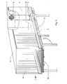
Figur 2 Schnittdarstellung der Bodengruppe des Behälters gemäß Figur 1.
- Figure 1 is a perspective view of the container, partially cut and
- FIG. 2 shows a sectional view of the bottom group of the container according to FIG. 1.
Bei dem Behälter 1 handelt es sich um einen Wechselbehälter in Form eines Kofferaufbaus der Klasse C nach DIN EN 284 und DIN EN 283 zum Transport und zur Lagerung von brennbaren und nicht brennbaren wassergefährdenden Flüssigkeiten in kubischen Tankcontainern (KTC) und Großpackmitteln (IBC) sowie Fässern, Kanistern und sonstigen ortsbeweglichen Gefäßen. Gemäß DIN EN 284 besteht der Behälter 1 aus Stahl.Container 1 is an interchangeable container in the form of a box body of class C according to DIN EN 284 and DIN EN 283 for the transport and storage of flammable and non-flammable water-polluting liquids in cubic tank containers (KTC) and large packaging (IBC) as well as barrels , Canisters and other portable vessels. According to DIN EN 284, container 1 is made of steel.
Der Kofferaufbau ist durch zwei in Längsrichtung verlaufende Seitenwände 2, 3, zwei Stirnwände 4 (nicht dargestellt), 5 und ein Dach 6 realisiert, die auf einer Bodengruppe befestigt sind. Die Stirnwände 4, 5 weisen Belüftungsöffnungen 7 auf, die zueinander höhenversetzt angeordnet und mit jeweils einem Deckel 8 dicht verschließbar sind. Betätigungsorgane 9 erlauben die Betätigung der Deckel 8, die auf diese Weise ein Öffnen oder Verschließen der Belüftungsöffnungen 7 ohne Zuhilfenahme von Leitern o.ä. auch im aufgeständerten Zustand erlauben. Die Betätigungselemente 9 sind in an sich bekannter Weise ausgeführt und erlauben ein Verriegeln durch einen hier nicht näher dargestellten Verschlußmechanismus, der sich im unteren Bereich eines Querträgers 13 befindet.The box body is realized by two longitudinally extending
Die Belüftungsöffnungen 7 sind höhenversetzt angeordnet, d.h. eine der beiden Belüftungsöffnungen ist in Bodennähe, die andere Belüftungsöffnung in Dachnähe angebracht. Infolge der Höhendifferenz erfolgt ein selbsttätiger Luftaustausch selbst bei geringen Luftgeschwindigkeiten. Die Belüftungsöffnungen 7 sind als Belüftungsklappen ausgeführt.The ventilation openings 7 are arranged offset in height, i.e. one of the two ventilation openings is near the floor, the other ventilation opening near the roof. Due to the difference in altitude, the air is automatically exchanged even at low air speeds. The ventilation openings 7 are designed as ventilation flaps.
Der Aufbau der Bodenkonstruktion ergibt sich insbesondere aus Figur 2. Sie besteht im wesentlichen aus einer Bodenwanne 10, die ein in Längsrichtung profiliertes Bodenblech 11 aufweist. Im dargestellten Ausführungsbeispiel ist die Profilierung sickenartig gestaltet. Sie dient zunächst dazu, die Stabilität der Bodenwanne 10 zu stärken.The structure of the floor construction results in particular from FIG. 2. It essentially consists of a
Das Bodenblech 11 ist mit zwei seitlich durchgehend in Längsrichtung verlaufenden Längsträgern 12 und zwei stirnseitig angeordneten Querträgern 13 verbunden, die damit integrale Bestandteile der Bodenwanne 10 sind. Innerhalb der Bodenwanne 10 sind Querträger 14 zwischen den Längsträgern 12 verlaufend angeordnet und mit diesen verbunden. Sie verleihen als weitere Bestandteile der Bodenwanne 10 die nötige Endstabilität. Im dargestellten Ausführungsbeispiel nicht dargestellt ist die Art der Verbindung von Bodenblech 11, Längsträgern 12 und Querträgern 13, 14 in Form einer Schweißverbindung. Zur weiteren Erhöhung der Stabilität kann zusätzlich das Bodenblech 11 mit den innenliegenden Querträgern 14 verschweißt sein. Hierbei ist jeweils der Querträger 14 nicht durchgehend mit dem Bodenblech 11 verschweißt, sondern lediglich in den erhaben ausgeformten Abschnitten. Die Vertiefungen 17 hingegen bilden jeweils in Längsrichtung durchgehend verlaufende Rinnen, so daß ausgetretene Flüssigkeit ungehindert durchtreten kann.The
Speziell für die Verbindung zwischen den innenliegenden Querträgern 14 und dem Bodenblech 11 eignen sich auch alternative Verbindungstechniken, wie beispielsweise Kleben.Alternative connection techniques, such as gluing, are also particularly suitable for the connection between the
Außen sind am Bodenblech 11 zwei Führungsprofile 16 in Längsrichtung durchgehend angebracht. Die beiden Führungsprofile 16 sind in Übereinstimmung mit den Normen gewählt, so daß hierdurch ein Zentriertunnel gebildet ist. Die Führungsprofile 16 sind mit dem Bodenblech 11 verschweißt bzw. verklebt. Die Führungsprofile 16 dienen damit nicht nur zur zentrierenden Aufnahme von korrespondierenden, fahrzeugseitig angebrachten Führungselementen, sondern erhöhen weiterhin die Stabilität der Bodenwanne 10. Somit gelingt es, die Bodenwanne 10 als tragendes Element bzw. unmittelbar als Bodengruppe auszuführen. Die integrierten Längsträger 12 und Querträger 13, 14 in Verbindung mit dem profilierten Bodenblech 11 erlauben eine äußerst flache Gestaltung der Bodengruppe, wobei im vorliegenden Ausführungsbeispiel ein Aufnahmevolumen von 1250 Litern realisierbar ist. Die eingangs beschriebene kritische Höhe von 240 mm für die Bodengruppe wird dennoch nicht überschritten. Die Bodenwanne 10 genügt demnach den einschlägigen Vorschriften.On the outside, two
Die innerhalb der Bodenwanne 10 verlaufenden Querträger 14 sind U- und Vierkantprofile. Auf diesen ist unmittelbar der Bodenrost in Form einer Mehrfachanordnung einzelner Gitterroste 15 aufgelegt. Im konkreten Fall sind zwei Reihen zu je fünf Gitterrosten 15 vorgesehen. Die Gitterroste 15 sind ausreichend stabil ausgeführt, um die Befahrbarkeit für Gabelhubstapler oder Gabel-Handhubwagen zu gewährleisten.The
Weiterhin weist die Bodenwanne 10 in den Endbereichen der seitlichen Längsträger 12 einen nach innen zurückweichenden, kastenartigen Konturverlauf auf. Die hierdurch entstehenden Nischen dienen zur Aufnahme der Stützbeine 20 im eingeklappten Zustand. In diesem Zustand sind die Stützbeine so weit nach innen verlagert, daß sie seitlich und nach unten hin nicht die Außenkontur des Behälters 1 überragen. Die Stützbeine 20 sind jeweils an einem Traglager 21 angebracht, wobei die Traglager 21 aus Stabilitätsgründen unter Zwischenlage des Bodenblechs 11 an den innerhalb der Bodenwanne 10 angeordneten Querträgern 14 befestigt sind. Sie stützen sich somit an den Querträgern 14 ab.Furthermore, in the end regions of the side
Zweckmäßigerweise ist die Bodenwanne 10 mit einer verschließbaren Ablaßöffnung versehen. Zusätzlich kann unmittelbar benachbart ein Schauglas angebracht sein, so daß sich von außen, d.h. ohne Öffnen des Behälters 1, das Vorhandensein von eventuell ausgelaufener Flüssigkeit feststellen läßt. Sowohl die Ablaßöffnung als auch das Schauglas sind wiederum an einem zurückversetzt verlaufenden Abschnitt des Längsträgers 12 angebracht, so daß sie die Außenkontur des Behälters 1 nicht überragen. Zusätzlich kann die Bodenwanne 10 mit einem geringen Gefälle ausgeführt sein, so daß sich eventuell austretende Flüssigkeit an einer hierdurch gebildeten tiefsten Stelle ansammelt. Dieser Stelle zugeordnet sind dann die Ablaßöffnung und das Schauglas angebracht.The
Im vorliegenden Ausführungsbeispiel sind das Bodenblech 11, die Längsträger 12 und die Querträger 13, 14 aus Edelstahl gefertigt und damit gegenüber den meisten zu transportierenden und zu lagernden Flüssigkeiten beständig. Soll aus Kostengründen auf Edelstahl verzichtet werden, so ist es erforderlich, die Bodenwanne 10 innen vollständig mit einem beständigen Material zu beschichten.In the present exemplary embodiment, the
Somit gelingt es, einen Behälter 1 als Wechselcontainer nach DIN EN 284 zu realisieren, der so als Transport- als auch als Lagercontainer verwendbar ist. Er besitzt Halteeinrichtungen für die Bahn- und LKW-Beförderung sowie vier Stützbeine 20 nach DIN 70018. Es besteht somit die Möglichkeit, den Behälter 1 zur Lagerung von wassergefährdenden Flüssigkeiten mit oder ohne ausgeklappten Stützbeinen 20 aufzustellen. Dabei ergeben sich Bodenfreiheiten unterhalb des Behälters 1 von 100 mm bzw. 1220 mm. Die beiden Belüftungsöffnungen 7 erlauben die Lagerung brennbarer Flüssigkeiten der Gefahrenklassen Al, All und B. Diese werden bei der Benutzung des Behälters 1 als Transportcontainer verschlossen.It is thus possible to implement a container 1 as an interchangeable container in accordance with DIN EN 284, which can be used as a transport container as well as a storage container. It has holding devices for rail and truck transportation and four support legs 20 according to DIN 70018. It is therefore possible to set up the container 1 for storing water-polluting liquids with or without the support legs 20 folded out. This results in floor clearances below the container 1 of 100 mm or 1220 mm. The two ventilation openings 7 allow the storage of flammable liquids of hazard classes Al, All and B. These are closed when the container 1 is used as a transport container.
Der Behälter 1 genügt gleichzeitig einer Reihe von Vorschriften, beispielsweise dem Wasserhaushaltsgesetz (WHG), der Verordnung von Lagerung wassergefährdender Stoffe (VLwF) und den technischen Regeln für brennbare Flüssigkeiten (TRbF). Die Zulassung als Transportcontainer gemäß den Regeln des Internationalen Eisenbahnverbands (UIC) als auch gemäß CSC (Sicherheitszulassung gemäß Bundesgesetzblatt 11 1976, S. 253) ist ebenfalls möglich.Container 1 also complies with a number of regulations, such as the Water Resources Act (WHG), the regulation of the storage of water-polluting substances (VLwF) and the technical rules for flammable liquids (TRbF). Approval as a transport container in accordance with the rules of the International Union of Railways (UIC) and CSC (safety approval in accordance with
- 1 Behälter1 container
- 2 Seitenwand2 side wall
- 3 Seitenwand3 side wall
- 4 Stirnwand4 end wall
- 5 Stirnwand5 end wall
- 6 Dach6 roof
- 7 Belüftungsöffnung7 ventilation opening
- 8 Deckel8 lids
- 9 Betätigungsorgan9 actuator
- 10 Bodenwanne10 floor pan
- 11 Bodenblech11 bottom plate
- 12 Längsträger12 side members
- 13 Querträger13 cross members
- 14 Querträger14 cross beams
- 15 Gitterrost15 grating
- 16 Führungsprofil16 guide profile
- 17 Vertiefung17 deepening
- 20 Stützbein20 support leg
- 21 Traglager21 support bearings
Claims (11)
Applications Claiming Priority (2)
| Application Number | Priority Date | Filing Date | Title |
|---|---|---|---|
| DE4333793A DE4333793C2 (en) | 1993-10-04 | 1993-10-04 | Storage and transport containers |
| DE4333793 | 1993-10-04 |
Publications (3)
| Publication Number | Publication Date |
|---|---|
| EP0646532A2 true EP0646532A2 (en) | 1995-04-05 |
| EP0646532A3 EP0646532A3 (en) | 1996-01-24 |
| EP0646532B1 EP0646532B1 (en) | 1997-01-02 |
Family
ID=6499365
Family Applications (1)
| Application Number | Title | Priority Date | Filing Date |
|---|---|---|---|
| EP94115527A Expired - Lifetime EP0646532B1 (en) | 1993-10-04 | 1994-10-01 | Storage and transport container |
Country Status (3)
| Country | Link |
|---|---|
| EP (1) | EP0646532B1 (en) |
| AT (1) | ATE147047T1 (en) |
| DE (2) | DE4333793C2 (en) |
Cited By (3)
| Publication number | Priority date | Publication date | Assignee | Title |
|---|---|---|---|---|
| AT1138U1 (en) * | 1992-08-17 | 1996-11-25 | Zovos V O S | CONTAINERS FOR PROBLEMS |
| EP0761565A1 (en) * | 1995-09-06 | 1997-03-12 | GERHARD ENGINEERING GmbH | Container protection tray |
| CN113212996A (en) * | 2021-04-20 | 2021-08-06 | 中车太原机车车辆有限公司 | Container coupling device and coupling type container |
Citations (3)
| Publication number | Priority date | Publication date | Assignee | Title |
|---|---|---|---|---|
| DE2717396C2 (en) * | 1977-04-20 | 1979-05-03 | Ab Plastkarosser, Skellefteaa | Containers for transporting dangerous goods |
| EP0108745A2 (en) * | 1982-11-03 | 1984-05-16 | Michael Hofstetter | Supporting arrangement for containers and removable superstructures for trucks |
| GB2257123A (en) * | 1991-03-19 | 1993-01-06 | Adamson Modular Systems Limite | Swop body container jacking system. |
Family Cites Families (2)
| Publication number | Priority date | Publication date | Assignee | Title |
|---|---|---|---|---|
| DE9005093U1 (en) * | 1990-05-04 | 1990-07-12 | Fr. Gerbracht Stahlblech- Und Behaelterbau Gmbh & Co Kg, 5758 Froendenberg-Langschede, De | |
| DE9103293U1 (en) * | 1991-03-18 | 1991-06-20 | Nukem Gmbh, 8755 Alzenau, De |
-
1993
- 1993-10-04 DE DE4333793A patent/DE4333793C2/en not_active Expired - Fee Related
-
1994
- 1994-10-01 AT AT94115527T patent/ATE147047T1/en not_active IP Right Cessation
- 1994-10-01 DE DE59401458T patent/DE59401458D1/en not_active Expired - Fee Related
- 1994-10-01 EP EP94115527A patent/EP0646532B1/en not_active Expired - Lifetime
Patent Citations (3)
| Publication number | Priority date | Publication date | Assignee | Title |
|---|---|---|---|---|
| DE2717396C2 (en) * | 1977-04-20 | 1979-05-03 | Ab Plastkarosser, Skellefteaa | Containers for transporting dangerous goods |
| EP0108745A2 (en) * | 1982-11-03 | 1984-05-16 | Michael Hofstetter | Supporting arrangement for containers and removable superstructures for trucks |
| GB2257123A (en) * | 1991-03-19 | 1993-01-06 | Adamson Modular Systems Limite | Swop body container jacking system. |
Cited By (3)
| Publication number | Priority date | Publication date | Assignee | Title |
|---|---|---|---|---|
| AT1138U1 (en) * | 1992-08-17 | 1996-11-25 | Zovos V O S | CONTAINERS FOR PROBLEMS |
| EP0761565A1 (en) * | 1995-09-06 | 1997-03-12 | GERHARD ENGINEERING GmbH | Container protection tray |
| CN113212996A (en) * | 2021-04-20 | 2021-08-06 | 中车太原机车车辆有限公司 | Container coupling device and coupling type container |
Also Published As
| Publication number | Publication date |
|---|---|
| DE4333793C2 (en) | 1996-11-14 |
| ATE147047T1 (en) | 1997-01-15 |
| EP0646532A3 (en) | 1996-01-24 |
| EP0646532B1 (en) | 1997-01-02 |
| DE4333793A1 (en) | 1995-04-06 |
| DE59401458D1 (en) | 1997-02-13 |
Similar Documents
| Publication | Publication Date | Title |
|---|---|---|
| EP0510353B1 (en) | Collapsible cargo holder or container | |
| DE202009018780U1 (en) | large containers | |
| EP2147867B1 (en) | Storage cabinet | |
| DE202009010748U1 (en) | Device for transport and / or storage of dangerous goods / hazardous substances | |
| EP1277673B1 (en) | Collapsible container | |
| EP0646532B1 (en) | Storage and transport container | |
| DE102018118864B4 (en) | Container with transport frame as well as wheel and tire transport system | |
| DE102008005665A1 (en) | Large space container e.g. standard box container, for storing and transporting consumer goods, has defined container unit modifiably arranged in interior space of container, which is alternatively inserted in container dimensions | |
| DE4320054C2 (en) | Cylindrical container | |
| DE202021000806U1 (en) | Transport system with a modular container | |
| EP0314958B1 (en) | Device for the storage and/or transport of liquids polluting the environment | |
| DE3908103C2 (en) | ||
| EP0069921B1 (en) | Changing frame for container-transport vehicles having container locking devices, such as lorries, trailers or track-bound container-carrying cars | |
| EP0298383B1 (en) | Container for storage and transportation of loose material, such as rubble, garbage, industrial waste and the like | |
| EP0672012B1 (en) | Bulk material container with an emptying arrangement | |
| DE202010010624U1 (en) | transport system | |
| WO2022184329A1 (en) | Transport system having a modular container | |
| DE102015215098A1 (en) | transport container | |
| DE102022109976A1 (en) | LARGE LOAD CARRIER | |
| DE3545855A1 (en) | CONTAINER FOR WATER OR OTHER LIQUIDS | |
| DE102016012571B4 (en) | Swap bodies with integrated loading and unloading system | |
| DE102004023018B4 (en) | Transport container with hinged side walls and a bottom | |
| EP0541832A1 (en) | Container, in particular interchangeable container | |
| DE202021100652U1 (en) | Plant for conveying and storing transport goods | |
| DE4333626C2 (en) | Transport box made of plastic |
Legal Events
| Date | Code | Title | Description |
|---|---|---|---|
| PUAI | Public reference made under article 153(3) epc to a published international application that has entered the european phase |
Free format text: ORIGINAL CODE: 0009012 |
|
| AK | Designated contracting states |
Kind code of ref document: A2 Designated state(s): AT CH DE LI NL |
|
| PUAL | Search report despatched |
Free format text: ORIGINAL CODE: 0009013 |
|
| AK | Designated contracting states |
Kind code of ref document: A3 Designated state(s): AT CH DE LI NL |
|
| 17P | Request for examination filed |
Effective date: 19960206 |
|
| GRAG | Despatch of communication of intention to grant |
Free format text: ORIGINAL CODE: EPIDOS AGRA |
|
| GRAH | Despatch of communication of intention to grant a patent |
Free format text: ORIGINAL CODE: EPIDOS IGRA |
|
| 17Q | First examination report despatched |
Effective date: 19960521 |
|
| GRAH | Despatch of communication of intention to grant a patent |
Free format text: ORIGINAL CODE: EPIDOS IGRA |
|
| GRAA | (expected) grant |
Free format text: ORIGINAL CODE: 0009210 |
|
| AK | Designated contracting states |
Kind code of ref document: B1 Designated state(s): AT CH DE LI NL |
|
| REF | Corresponds to: |
Ref document number: 147047 Country of ref document: AT Date of ref document: 19970115 Kind code of ref document: T |
|
| REG | Reference to a national code |
Ref country code: CH Ref legal event code: NV Representative=s name: DIPL.-ING. ETH H. R. WERFFELI PATENTANWALT Ref country code: CH Ref legal event code: EP |
|
| REF | Corresponds to: |
Ref document number: 59401458 Country of ref document: DE Date of ref document: 19970213 |
|
| PLBE | No opposition filed within time limit |
Free format text: ORIGINAL CODE: 0009261 |
|
| STAA | Information on the status of an ep patent application or granted ep patent |
Free format text: STATUS: NO OPPOSITION FILED WITHIN TIME LIMIT |
|
| 26N | No opposition filed | ||
| PGFP | Annual fee paid to national office [announced via postgrant information from national office to epo] |
Ref country code: CH Payment date: 19980907 Year of fee payment: 5 |
|
| PGFP | Annual fee paid to national office [announced via postgrant information from national office to epo] |
Ref country code: AT Payment date: 19981022 Year of fee payment: 5 |
|
| PG25 | Lapsed in a contracting state [announced via postgrant information from national office to epo] |
Ref country code: AT Free format text: LAPSE BECAUSE OF NON-PAYMENT OF DUE FEES Effective date: 19991001 |
|
| PGFP | Annual fee paid to national office [announced via postgrant information from national office to epo] |
Ref country code: NL Payment date: 19991027 Year of fee payment: 6 |
|
| PG25 | Lapsed in a contracting state [announced via postgrant information from national office to epo] |
Ref country code: LI Free format text: LAPSE BECAUSE OF NON-PAYMENT OF DUE FEES Effective date: 19991031 Ref country code: CH Free format text: LAPSE BECAUSE OF NON-PAYMENT OF DUE FEES Effective date: 19991031 |
|
| PGFP | Annual fee paid to national office [announced via postgrant information from national office to epo] |
Ref country code: DE Payment date: 19991127 Year of fee payment: 6 |
|
| REG | Reference to a national code |
Ref country code: CH Ref legal event code: PL |
|
| PG25 | Lapsed in a contracting state [announced via postgrant information from national office to epo] |
Ref country code: NL Free format text: LAPSE BECAUSE OF NON-PAYMENT OF DUE FEES Effective date: 20010501 |
|
| NLV4 | Nl: lapsed or anulled due to non-payment of the annual fee |
Effective date: 20010501 |
|
| PG25 | Lapsed in a contracting state [announced via postgrant information from national office to epo] |
Ref country code: DE Free format text: LAPSE BECAUSE OF NON-PAYMENT OF DUE FEES Effective date: 20010703 |