EP0645906A1 - Optisches Kabelfernsehsystem - Google Patents
Optisches Kabelfernsehsystem Download PDFInfo
- Publication number
- EP0645906A1 EP0645906A1 EP94200247A EP94200247A EP0645906A1 EP 0645906 A1 EP0645906 A1 EP 0645906A1 EP 94200247 A EP94200247 A EP 94200247A EP 94200247 A EP94200247 A EP 94200247A EP 0645906 A1 EP0645906 A1 EP 0645906A1
- Authority
- EP
- European Patent Office
- Prior art keywords
- signals
- optical
- subscribers
- fdm
- channels
- Prior art date
- Legal status (The legal status is an assumption and is not a legal conclusion. Google has not performed a legal analysis and makes no representation as to the accuracy of the status listed.)
- Granted
Links
- 230000003287 optical effect Effects 0.000 title claims abstract description 41
- 239000000835 fiber Substances 0.000 description 4
- 239000003365 glass fiber Substances 0.000 description 2
- 239000013307 optical fiber Substances 0.000 description 2
- 238000006243 chemical reaction Methods 0.000 description 1
- 230000000694 effects Effects 0.000 description 1
Images
Classifications
-
- H—ELECTRICITY
- H04—ELECTRIC COMMUNICATION TECHNIQUE
- H04H—BROADCAST COMMUNICATION
- H04H20/00—Arrangements for broadcast or for distribution combined with broadcast
- H04H20/65—Arrangements characterised by transmission systems for broadcast
- H04H20/69—Optical systems
-
- H—ELECTRICITY
- H04—ELECTRIC COMMUNICATION TECHNIQUE
- H04J—MULTIPLEX COMMUNICATION
- H04J14/00—Optical multiplex systems
- H04J14/02—Wavelength-division multiplex systems
- H04J14/0298—Wavelength-division multiplex systems with sub-carrier multiplexing [SCM]
-
- H—ELECTRICITY
- H04—ELECTRIC COMMUNICATION TECHNIQUE
- H04N—PICTORIAL COMMUNICATION, e.g. TELEVISION
- H04N7/00—Television systems
- H04N7/22—Adaptations for optical transmission
Definitions
- the invention relates to a distribution system for simultaneously distributing signals, such as TV signals, belonging to different FDM channels from an exchange, via an optical network, to subscribers connected to said network, the signals being converted, on the side of said exchange, from electrical signals into optical signals.
- signals for example baseband TV signals - are frequency-multiplexed in their electric form so that they can be transmitted via different FDM channels to the subscriber side.
- the signals can once more be demultiplexed. Hitherto it was common usage for the signals of all the FDM channels to be converted, at the transmitting side (exchange side), by one and the same E/O converter (transmitting laser) and to transmit the optical signal consisting of more FDM channels to the subscriber side.
- the electrical signal which therefore comprises all the FDM channels, is thus fed to a number of transmitting lasers which are each intended for a group of subscribers, and the subscribers belonging to that group provide all the FDM channels.
- a signal is again distributed over the various subscribers and converted, per subscriber, into an electrical signal.
- the electrical signal presented to a subscriber thus comprises all FDM channels.
- intermodulation occurs, particularly in the transmitting lasers - which, after all, convert all the FDM channels - as a result of non-linearity in the conversion characteristics of the transmitting lasers.
- Said intermodulation manifests itself in particular owing to the electrical signals having to be converted into optical signals, by one and the same laser, over the whole frequency range of all the FDM channels.
- a related problem is that in some cases intermodulation also occurs, as a result of distortion, in the optical fibres which transmit the converted optical signals to the subscriber side.
- the present invention is based on the following insight.
- a large number of transmitting lasers is already required.
- This large number of transmitting lasers makes it possible to limit, per transmitting laser, the frequency range of the signals to be converted, without the total number of lasers becoming greater as a result.
- the intermodulation mentioned is avoided, however.
- Said limitation of the frequency range can be achieved by converting only one FDM channel, or alternatively a limited number of FDM channels per laser, and by only then, in the optical domain, combining the entire group of FDM channels and presenting them to the subscribers.
- Said combination of the optical signals can be effected on the side of the exchange or on the side of the subscribers. Especially if the distance between the exchange and the subscribers is large, it is preferable to combine together the signals of the various FDM channels on the subscriber side. In this case too it is true that, owing to the large number of subscribers, a large number of fibres is nevertheless already required, and that this number does not increase if those fibres are shared out among the various FDM channels.
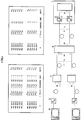
- Figure 1 shows an illustrative embodiment of the invention, in which different channels are converted by different transmitting lasers and the optical output signals are transmitted via separate fibres to the subscriber side where they are combined and presented to the subscribers.
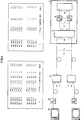
- Figure 2 shows an illustrative embodiment, in which the signals of different channels are converted by different transmitting lasers and the optical output signals are combined with one another and in that form are transmitted via fibres to the subscriber side and are presented to the subscribers.
- Both figures comprise, for the sake of clearity a table, presenting various channels, frequencies and wave lenghts.
- Figure 1 shows a distribution exchange 1 for TV signals, also known as "head-end".
- 30 TV channels are generated therein.
- the signals of these channels are converted by 30 lasers 2 into optical signals s 1...30 .
- These 30 optical signals are transmitted via 30 optical fibres f 1...30 to the subscriber side where an optical splitter/combiner 3 combines the signals - which each represent one FDM channel - optically with one another, which combined signals are distributed over various outputs, for example 40.
- the output signals s 31...70 - in each of which therefore all 30 FDM channels are represented - are transmitted, via optical fibres f 31...70 to an end splitter 4, where such a combined signal is distributed over a number of outputs, for example 10.
- Each output signal thereof is passed to a subscriber line in which there is an optical receiver 5 which converts the optical signal received (which represents all the FDM channels), into a corresponding electrical signal, the input signal for a connected TV receiver 6.
- Figure 2 shows the second preferred version of the invention, namely that in which on the transmitting side, in the "head-end", the different FDM channels are converted by the different transmitting lasers 2 into optical signals s 1...30 which each represent one FDM channel.
- the optical signals s 1...30 are combined with one another already on the transmitting side, namely in the "head-end” in a splitter/combiner 3.
- the output signals which therefore each represent all 30 FDM channels, are passed to the subscriber side via, for example, 40 optical fibres f 31...70 .
- There each fibre runs to the input of an end splitter 4 which distributes the signal over, for example, 10 subscriber lines in which optical receivers 5 convert the signal into an electrical signal.
- the first option shown in Figure 1 is, in principle, to be preferred to the option of Figure 2, since in the first option the (long) optical fibres f 1...30 , between the "head-end" side and the subscriber side, each separately transmit FDM channels separated from each other, as a result of which intermodulation, which occurs particularly in long fibres, is precluded. If within a not excessively large distance from the location of the splitter/combiner 3 there are a large number of subscribers, the fibres f 31...70 do not become too long and the intermodulation (after all, each of these fibres transmits all the FDM channels in combined form) in said fibres remains limited.
- the first comment concerns said distortion in the optical fibres f 1...30 and f 31...70 .
- This distortion occurs, in particular, when using 1300 Nm fibres to which, for the purpose of amplifying the optical signal, Erbium-Doped Fibre Amplifiers (EDFAs) are connected, which function optimally in the wavelength range of 1500 Nm but are less suitable for 1300 Nm. So far, however, no 1300 Nm fibre amplifiers are available, whereas 1300 Nm glass fibres are widely used.
- EDFAs Erbium-Doped Fibre Amplifiers
- the invention makes provision for limiting the frequency range per transmitting laser (and preferably also per optical fibre).
- the frequency range is limited and the effect of the distortion of the transmitting laser or optical fibre, respectively, is limited, albeit to a somewhat lesser extent.
- the choice made in this context depends on the actual characteristics of the lasers and the fibres and on the actual form of the network of which the fibres form part, which depends strongly on the geometric distribution of the subscribers (for example subscribers in an urban district with flats or subscribers in a rural environment).
Landscapes
- Engineering & Computer Science (AREA)
- Signal Processing (AREA)
- Multimedia (AREA)
- Computer Networks & Wireless Communication (AREA)
- Optical Communication System (AREA)
- Communication Cables (AREA)
- Closed-Circuit Television Systems (AREA)
Applications Claiming Priority (2)
| Application Number | Priority Date | Filing Date | Title |
|---|---|---|---|
| NL9300281 | 1993-02-12 | ||
| NL9300281A NL9300281A (nl) | 1993-02-12 | 1993-02-12 | Optisch CATV systeem. |
Publications (2)
| Publication Number | Publication Date |
|---|---|
| EP0645906A1 true EP0645906A1 (de) | 1995-03-29 |
| EP0645906B1 EP0645906B1 (de) | 2001-09-05 |
Family
ID=19862064
Family Applications (1)
| Application Number | Title | Priority Date | Filing Date |
|---|---|---|---|
| EP94200247A Expired - Lifetime EP0645906B1 (de) | 1993-02-12 | 1994-02-09 | Optisches Kabelfernsehsystem |
Country Status (4)
| Country | Link |
|---|---|
| EP (1) | EP0645906B1 (de) |
| AT (1) | ATE205349T1 (de) |
| DE (1) | DE69428172D1 (de) |
| NL (1) | NL9300281A (de) |
Citations (1)
| Publication number | Priority date | Publication date | Assignee | Title |
|---|---|---|---|---|
| WO1989009518A1 (en) | 1988-03-24 | 1989-10-05 | British Telecommunications Public Limited Company | Communication system |
-
1993
- 1993-02-12 NL NL9300281A patent/NL9300281A/nl not_active Application Discontinuation
-
1994
- 1994-02-09 DE DE69428172T patent/DE69428172D1/de not_active Expired - Lifetime
- 1994-02-09 AT AT94200247T patent/ATE205349T1/de not_active IP Right Cessation
- 1994-02-09 EP EP94200247A patent/EP0645906B1/de not_active Expired - Lifetime
Patent Citations (1)
| Publication number | Priority date | Publication date | Assignee | Title |
|---|---|---|---|---|
| WO1989009518A1 (en) | 1988-03-24 | 1989-10-05 | British Telecommunications Public Limited Company | Communication system |
Non-Patent Citations (6)
| Title |
|---|
| HIROMU TOBA ET AL.: "Factors affecting the design of optical FDM information distibution systems", IEEE JOURNAL ON SELECTED AREAS IN COMMUNICATION., vol. 8, no. 6, 1 August 1990 (1990-08-01), NEW YORK US, pages 965 - 972, XP000208591, DOI: doi:10.1109/49.57799 * |
| KAZOVSKY, LG: "Optical signal processing for lightwave communications networks", IEEE J SEL AR COMMUN, vol. 8, 6 August 1990 (1990-08-06), pages 973 - 982, XP000208592, DOI: doi:10.1109/49.57800 |
| LEONID G. KAZOVSKY: "Optical signal processing for lightwave communications networks.", IEEE JOURNAL ON SELECTED AREAS IN COMMUNICATION., vol. 8, no. 6, 1 August 1990 (1990-08-01), NEW YORK US, pages 973 - 982, XP000208592, DOI: doi:10.1109/49.57800 * |
| STUART S. WAGNER ET AL.: "WDM applications in broadband telecommunications networks.", IEEE COMMUNICATIONS MAGAZINE, vol. 29, no. 3, 1 March 1989 (1989-03-01), PISCATAWAY, NJ US, pages 22 - 30 * |
| TOBA. H: "Factors affecting the design of optical FDM information distribution system", IEEE J SEL AR COMMUN, vol. 8, 6 August 1990 (1990-08-06), pages 965 - 972, XP000208591, DOI: doi:10.1109/49.57799 |
| WAGNER. SS: "WDM applications in broadband telecommunications networks", IEEE COMMUN MAG, vol. 29, 3 March 1989 (1989-03-03), pages 22 - 30 |
Also Published As
| Publication number | Publication date |
|---|---|
| DE69428172D1 (de) | 2001-10-11 |
| ATE205349T1 (de) | 2001-09-15 |
| EP0645906B1 (de) | 2001-09-05 |
| NL9300281A (nl) | 1994-09-01 |
Similar Documents
| Publication | Publication Date | Title |
|---|---|---|
| US5153763A (en) | CATV distribution networks using light wave transmission lines | |
| US5963844A (en) | Hybrid fiber-coax system having at least one digital fiber node and increased upstream bandwidth | |
| US5864748A (en) | Hybrid fiber-coax system having at least one digital fiber node and increased upstream and downstream bandwidth | |
| US5430568A (en) | Optical communications system for transmitting information signals having different wavelengths over a same optical fiber | |
| US5793506A (en) | Optical transmission system for cable television signals and video and telecommunications signals | |
| US6097533A (en) | Optical amplifier for CATV system with forward and reverse paths | |
| US5262883A (en) | CATV distribution networks using light wave transmission lines | |
| US5847852A (en) | Optical network | |
| JP2001526494A (ja) | 波長分割多重化を使用するディジタル電話及びアナログビデオを同時伝送する方法及び装置 | |
| JPH06292038A (ja) | 旅客移動体内映像分配装置 | |
| JPS5925440A (ja) | テレビジヨン信号用分配ネツトワ−ク | |
| US20040131358A1 (en) | Passive optical network system providing simultaneously both broadcasting service and data service | |
| US6091869A (en) | Low loss, optical add/drop WDM node | |
| AU736033B2 (en) | An optical transmission system | |
| WO2000064087A1 (en) | Increased capacity bidirectional dwdm network architecture with frequency stacking system | |
| WO1998049794A2 (en) | Low loss, optical add/drop wdm node | |
| EP0645906B1 (de) | Optisches Kabelfernsehsystem | |
| EP1235434A2 (de) | Zweiwegnetzwerk zur Verteilung von Kabel-TV-Signalen an Endpunkte mittels optischer Fasern | |
| JPH0846594A (ja) | 光信号伝送装置 | |
| EP0735768A1 (de) | Lichtwellenleiter-Videonetzwerkarchitektur mit verteilten Videoquellen | |
| CA3017061A1 (en) | Aggregator-based cost-optimized communications topology for a point-to-multipoint network | |
| JPS63148724A (ja) | Catvシステムにおけるテレビ画像信号多重伝送方法 | |
| AU631608B2 (en) | System for distributing broadband signals over a branched coaxial cable network | |
| JPH10154962A (ja) | 光伝送システム | |
| US5673267A (en) | Method of allocating carrier frequencies for simultaneous transmission of a plurality of modulated signals especially on an optical link |
Legal Events
| Date | Code | Title | Description |
|---|---|---|---|
| PUAI | Public reference made under article 153(3) epc to a published international application that has entered the european phase |
Free format text: ORIGINAL CODE: 0009012 |
|
| AK | Designated contracting states |
Kind code of ref document: A1 Designated state(s): AT BE CH DE DK ES FR GB GR IE IT LI LU NL PT SE |
|
| 17P | Request for examination filed |
Effective date: 19950208 |
|
| 17Q | First examination report despatched |
Effective date: 19980615 |
|
| RAP3 | Party data changed (applicant data changed or rights of an application transferred) |
Owner name: KONINKLIJKE KPN N.V. |
|
| RIC1 | Information provided on ipc code assigned before grant |
Free format text: 7H 04N 7/22 A, 7H 04H 1/02 B |
|
| RIC1 | Information provided on ipc code assigned before grant |
Free format text: 7H 04N 7/22 A, 7H 04H 1/02 B |
|
| GRAG | Despatch of communication of intention to grant |
Free format text: ORIGINAL CODE: EPIDOS AGRA |
|
| GRAG | Despatch of communication of intention to grant |
Free format text: ORIGINAL CODE: EPIDOS AGRA |
|
| GRAH | Despatch of communication of intention to grant a patent |
Free format text: ORIGINAL CODE: EPIDOS IGRA |
|
| GRAH | Despatch of communication of intention to grant a patent |
Free format text: ORIGINAL CODE: EPIDOS IGRA |
|
| GRAA | (expected) grant |
Free format text: ORIGINAL CODE: 0009210 |
|
| AK | Designated contracting states |
Kind code of ref document: B1 Designated state(s): AT BE CH DE DK ES FR GB GR IE IT LI LU NL PT SE |
|
| PG25 | Lapsed in a contracting state [announced via postgrant information from national office to epo] |
Ref country code: NL Free format text: LAPSE BECAUSE OF FAILURE TO SUBMIT A TRANSLATION OF THE DESCRIPTION OR TO PAY THE FEE WITHIN THE PRESCRIBED TIME-LIMIT Effective date: 20010905 Ref country code: IT Free format text: LAPSE BECAUSE OF FAILURE TO SUBMIT A TRANSLATION OF THE DESCRIPTION OR TO PAY THE FEE WITHIN THE PRESCRIBED TIME-LIMIT;WARNING: LAPSES OF ITALIAN PATENTS WITH EFFECTIVE DATE BEFORE 2007 MAY HAVE OCCURRED AT ANY TIME BEFORE 2007. THE CORRECT EFFECTIVE DATE MAY BE DIFFERENT FROM THE ONE RECORDED. Effective date: 20010905 Ref country code: FR Free format text: LAPSE BECAUSE OF FAILURE TO SUBMIT A TRANSLATION OF THE DESCRIPTION OR TO PAY THE FEE WITHIN THE PRESCRIBED TIME-LIMIT Effective date: 20010905 Ref country code: BE Free format text: LAPSE BECAUSE OF FAILURE TO SUBMIT A TRANSLATION OF THE DESCRIPTION OR TO PAY THE FEE WITHIN THE PRESCRIBED TIME-LIMIT Effective date: 20010905 |
|
| REF | Corresponds to: |
Ref document number: 205349 Country of ref document: AT Date of ref document: 20010915 Kind code of ref document: T |
|
| REG | Reference to a national code |
Ref country code: CH Ref legal event code: NV Representative=s name: ISLER & PEDRAZZINI AG Ref country code: CH Ref legal event code: EP |
|
| PG25 | Lapsed in a contracting state [announced via postgrant information from national office to epo] |
Ref country code: AT Free format text: LAPSE BECAUSE OF FAILURE TO SUBMIT A TRANSLATION OF THE DESCRIPTION OR TO PAY THE FEE WITHIN THE PRESCRIBED TIME-LIMIT Effective date: 20010919 |
|
| REF | Corresponds to: |
Ref document number: 69428172 Country of ref document: DE Date of ref document: 20011011 |
|
| REG | Reference to a national code |
Ref country code: IE Ref legal event code: FG4D |
|
| PG25 | Lapsed in a contracting state [announced via postgrant information from national office to epo] |
Ref country code: SE Free format text: LAPSE BECAUSE OF FAILURE TO SUBMIT A TRANSLATION OF THE DESCRIPTION OR TO PAY THE FEE WITHIN THE PRESCRIBED TIME-LIMIT Effective date: 20011205 Ref country code: PT Free format text: LAPSE BECAUSE OF FAILURE TO SUBMIT A TRANSLATION OF THE DESCRIPTION OR TO PAY THE FEE WITHIN THE PRESCRIBED TIME-LIMIT Effective date: 20011205 Ref country code: DK Free format text: LAPSE BECAUSE OF FAILURE TO SUBMIT A TRANSLATION OF THE DESCRIPTION OR TO PAY THE FEE WITHIN THE PRESCRIBED TIME-LIMIT Effective date: 20011205 |
|
| PG25 | Lapsed in a contracting state [announced via postgrant information from national office to epo] |
Ref country code: DE Free format text: LAPSE BECAUSE OF FAILURE TO SUBMIT A TRANSLATION OF THE DESCRIPTION OR TO PAY THE FEE WITHIN THE PRESCRIBED TIME-LIMIT Effective date: 20011206 |
|
| PG25 | Lapsed in a contracting state [announced via postgrant information from national office to epo] |
Ref country code: GR Free format text: LAPSE BECAUSE OF FAILURE TO SUBMIT A TRANSLATION OF THE DESCRIPTION OR TO PAY THE FEE WITHIN THE PRESCRIBED TIME-LIMIT Effective date: 20011207 |
|
| REG | Reference to a national code |
Ref country code: GB Ref legal event code: IF02 |
|
| NLV1 | Nl: lapsed or annulled due to failure to fulfill the requirements of art. 29p and 29m of the patents act | ||
| PG25 | Lapsed in a contracting state [announced via postgrant information from national office to epo] |
Ref country code: LU Free format text: LAPSE BECAUSE OF NON-PAYMENT OF DUE FEES Effective date: 20020209 Ref country code: GB Free format text: LAPSE BECAUSE OF NON-PAYMENT OF DUE FEES Effective date: 20020209 |
|
| PG25 | Lapsed in a contracting state [announced via postgrant information from national office to epo] |
Ref country code: IE Free format text: LAPSE BECAUSE OF NON-PAYMENT OF DUE FEES Effective date: 20020211 |
|
| PG25 | Lapsed in a contracting state [announced via postgrant information from national office to epo] |
Ref country code: LI Free format text: LAPSE BECAUSE OF NON-PAYMENT OF DUE FEES Effective date: 20020228 Ref country code: CH Free format text: LAPSE BECAUSE OF NON-PAYMENT OF DUE FEES Effective date: 20020228 |
|
| PG25 | Lapsed in a contracting state [announced via postgrant information from national office to epo] |
Ref country code: ES Free format text: LAPSE BECAUSE OF FAILURE TO SUBMIT A TRANSLATION OF THE DESCRIPTION OR TO PAY THE FEE WITHIN THE PRESCRIBED TIME-LIMIT Effective date: 20020326 |
|
| PLBE | No opposition filed within time limit |
Free format text: ORIGINAL CODE: 0009261 |
|
| STAA | Information on the status of an ep patent application or granted ep patent |
Free format text: STATUS: NO OPPOSITION FILED WITHIN TIME LIMIT |
|
| 26N | No opposition filed | ||
| GBPC | Gb: european patent ceased through non-payment of renewal fee |
Effective date: 20020209 |
|
| REG | Reference to a national code |
Ref country code: CH Ref legal event code: PL |
|
| REG | Reference to a national code |
Ref country code: IE Ref legal event code: MM4A |