EP0645490B1 - Procédé et équipement pour lubrifier la lame d'une raclette dans une machine à papier ou carton - Google Patents
Procédé et équipement pour lubrifier la lame d'une raclette dans une machine à papier ou carton Download PDFInfo
- Publication number
- EP0645490B1 EP0645490B1 EP94114473A EP94114473A EP0645490B1 EP 0645490 B1 EP0645490 B1 EP 0645490B1 EP 94114473 A EP94114473 A EP 94114473A EP 94114473 A EP94114473 A EP 94114473A EP 0645490 B1 EP0645490 B1 EP 0645490B1
- Authority
- EP
- European Patent Office
- Prior art keywords
- roll
- lubricating medium
- blade
- compartment
- jet pipe
- Prior art date
- Legal status (The legal status is an assumption and is not a legal conclusion. Google has not performed a legal analysis and makes no representation as to the accuracy of the status listed.)
- Expired - Lifetime
Links
- 230000001050 lubricating effect Effects 0.000 title claims abstract description 35
- 238000000034 method Methods 0.000 title claims abstract description 11
- 239000000314 lubricant Substances 0.000 claims description 14
- XLYOFNOQVPJJNP-UHFFFAOYSA-N water Substances O XLYOFNOQVPJJNP-UHFFFAOYSA-N 0.000 claims description 6
- 238000005192 partition Methods 0.000 claims description 3
- 238000011144 upstream manufacturing Methods 0.000 claims 2
- 238000005461 lubrication Methods 0.000 description 3
- 239000000463 material Substances 0.000 description 3
- 230000001105 regulatory effect Effects 0.000 description 2
- 238000004140 cleaning Methods 0.000 description 1
- 238000010276 construction Methods 0.000 description 1
Images


Classifications
-
- D—TEXTILES; PAPER
- D21—PAPER-MAKING; PRODUCTION OF CELLULOSE
- D21G—CALENDERS; ACCESSORIES FOR PAPER-MAKING MACHINES
- D21G3/00—Doctors
- D21G3/005—Doctor knifes
Definitions
- the invention concerns a method of lubricating a doctor blade applied against the outer surface of a roll in a paper machine / board machine according to the preamble of claim 1, and a roll provided with a doctor and means for applying a lubricating medium on the outer surface of the roll according to the preamble of claim 5.
- the doctor blades on the centre roll of the press are worn one-sidely. This comes from a number of reasons, which vary in the cross direction of the machine. Uneven wear is affected, e.g. by the temperature, air flows, etc. factors. Uneven wear rapidly results in replacement of the doctor blade. The wear of the blade is measured, and when the wear exceeds a permitted maximal wear, the blade is replaced. Thus, if the wear of the blade can be made more uniform, it is possible to extend the service life of the blade and to increase the interval of replacement.
- the lubrication jets of doctors are designed symmetric. However, it has been noticed that, in view of equalization of the wear of blades, a larger amount of lubricant should be introduced in the portion of the blade width that is worn more rapidly.
- DE 43 03 315 A1 discloses a method and a device for cleaning endless and rotating surfaces in a paper machine.
- a web of material is brought into contact with the rotating surface and at least one doctor is used the blade of which acts in an area of the rotating surface which is not used by the web of material.
- wet air is applied to the rotating surface in the area not used by the web of material.
- the lubrication pipe be divided into sections. It is a second alternative that different quantities of lubricating medium are introduced through separate pipe constructions of different portions of the doctor width. Thus, in the present application, it is suggested that a profiled lubrication jet be used, whereby the wear profile of the blade can be equalized.
- the method in accordance with the invention of lubricating a doctor is mainly characterized in that different quantities of lubricating medium are applied in different areas of the width of the roll, a larger amount of lubricating medium being applied in the area corresponding to the area of the width of the blade in which the maximum extent of wear of the blade has been noticed.
- the equipment in accordance with the invention is mainly characterized in that the means for applying lubricating medium comprise means, preferably lubricants ducts, through which different quantities of lubricating medium, preferably water, can be applied to different portions of the width of the roll and thereby supplied to different portions of the width of the blade.
- the means for applying lubricating medium comprise means, preferably lubricants ducts, through which different quantities of lubricating medium, preferably water, can be applied to different portions of the width of the roll and thereby supplied to different portions of the width of the blade.
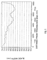
- Fig. 1 illustrates the wear taking place in prior-art doctor operations with uniform and symmetric supply of lubricating medium.
- the vertical system of coordinates represents the measured blade width.
- the distance from the tending-side end is indicated in the horizontal system of coordinates as millimetres. It is seen that the measured wear is uneven, increasing towards the driving-side end.
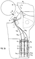
- Fig. 2A is a side view of a solution of equipment in accordance with the invention.
- the doctor blade 11 doctors the roll 10 face, and the jet S is introduced from the jet pipe 12 to the forward side of the doctor blade 11.
- the sense of rotation of the roll is indicated by the arrow L 1 .
- three lubricant ducts are passed, i.e.
- the ducts 13a 1 ,13a 2 and 13a 3 which comprise regulation valves 14a 1 , 14a 2 , 14a 3 for regulation of the flow quantity and, as is shown in the figure, flow meters and pressure gauges C 1 ,C 2 ,C 3 ,D 1 ,D 2 ,D 3 , from which it is possible to monitor the amount of flowing medium passing into each compartment.
- the lubricating medium is passed into the compartment G 1 in the interior of the jet pipe 12.
- the lubricating medium is passed into the compartment G 2 in the interior of the jet pipe 12, and through the duct 13a 3 the lubricating medium is passed into the compartment G 3 in the interior of the jet pipe 12.
- Fig. 2B shows the solution of equipment as viewed in the direction of the arrow K 1 in Fig. 2A.
- the lubricant jets S 1 are produced from the compartment G 1
- the lubricant jets S 2 are produced from the compartment G 2
- the lubricant jets S 3 are produced from the compartment G 3 .
- the jet pipe 12 has been divided into compartment. Through each compartment, the desired quantity of medium flow per metre of doctor width per unit of time is produced.
- the amount of lubricant is increased at the portion of the width of the doctor blade at which the most intensive wear has been noticed.
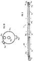
- FIG. 2C is a sectional view of the jet pipe 12.
- the jet pipe 12 comprises a frame mantle 12a and therein jet nozzles 12b 1 ,12b 2 ... as well as partition walls 12c 1 ,12c 2 and end walls 12d 1 , 12d 2 , by whose means the interior of the jet pipe 12 has been divided into the compartments G 1 ,G 2 and G 3 .
- the lubricant duct 13a 1 passes into the compartment G 1 .
- the lubricant duct 13a 2 passes into the compartment G 2
- the lubricant duct 13a 3 passes into the compartment G 3 .
- As the lubricating medium preferably water is used.
- each compartment G 1 ,G 2 and G 3 comprises an emptying plug 20a 1 ,20a 2 ,20a 3 , which is placed underneath when the pipe is installed in its position. When the plug is removed, the compartments G 1 ,G 2 ,G 3 can be emptied of water independently from one another.
- Fig. 2D is a sectional view taken along the line I-I in Fig. 2B.
- a water jet is passed from the compartment G 1 through the jet nozzles 12b 1 ,12b 2 ... onto the face 10' of the roll 10 and further, on the roll face, into connection with the doctor blade 11.
- Fig. 3 shows an embodiment of the invention in which the jet pipe 120, which is shown as a sectional view, additionally comprises an exhaust duct 21a 1 ,21a 2 ,21a 3 passing from each compartment G 1 ,G 2 ,G 3 , in which case each compartment G 1 ,G 2 ,G 3 can also be emptied by running through, by opening the closing valves M 1 ,M 2 ,M 3 connected with said exhaust ducts.
- Fig. 4 shows an embodiment of the invention in which there are three separate jet pipes, i.e. the jet pipes 120a 1 , 120a 2 , 120a 3 .
- the amount of lubricating medium supplied by each separate jet pipe is regulated by means of a regulation valve 14a 1 , 14a 2 ,14a 3 of its own.
Landscapes
- Paper (AREA)
Claims (11)
- Procédé pour lubrifier une lame de raclette (11) appliquée contre la surface extérieure (10') d'un cylindre (10) dans une machine à papier ou à carton, dans lequel un milieu lubrifiant est appliqué sur la surface extérieure (10') du cylindre (10) en amont de la lame de raclette (11) par rapport au sens de rotation (L1) du cylindre (10) pour empêcher l'usure de la lame de raclette (11) en alimentant la lame (11) en milieu lubrifiant,
caractérisé en ce que
l'on applique différentes quantités de milieu lubrifiant dans différentes zones de la largeur du cylindre (10), une plus grande quantité de milieu lubrifiant étant appliquée dans la zone correspondant à la zone de la largeur de la lame (11) dans laquelle l'étendue maximale de l'usure de la lame (11) a été relevée. - Procédé selon la revendication 1,
caractérisé en ce que
dans ledit procédé, on utilise une tuyère d'éjection (12) qui a été divisée en compartiments et qui comprend au moins deux compartiments (G1, G2...), d'où sont fournies différentes quantités de milieu lubrifiant à différentes zones de la largeur du cylindre (10). - Procédé selon la revendication 2,
caractérisé en ce que
dans ledit procédé, on mesure la quantité écoulée par unité de temps dans/hors de chaque compartiment (G1, G2...) de la tuyère d'éjection (12). - Procédé selon l'une quelconque des revendications précédentes,
caractérisé en ce que
l'on utilise de l'eau comme milieu lubrifiant, l'eau étant pulvérisée sur la face (10') du cylindre (10) contre laquelle la lame de raclette (11) est placée. - Cylindre (10) comprenant une raclette ayant une lame de raclette (11) appliquée contre la surface extérieure (10') du cylindre (10) et des moyens (12; 120; 120a1; 120a2; 120a3) pour appliquer un milieu lubrifiant sur la surface extérieure (10') du cylindre (10) en amont de la lame (11) par rapport au sens de rotation (L1) du cylindre (10) de manière à empêcher l'usure de la lame de raclette (11) en alimentant la lame (11) en milieu lubrifiant,
caractérisé en ce que
les moyens (12; 120; 120a1; 120a2; 120a3) pour appliquer du milieu lubrifiant comprennent des moyens, de préférence des conduits de lubrifiant (13a1, 13a2, 13a3), par lesquels différentes quantités de milieu lubrifiant, de préférence de l'eau, peuvent être fournies à différentes parties de la largeur du cylindre (10) et, de ce fait, à différentes parties de la largeur de la lame (11). - Cylindre selon la revendication précédente,
caractérisé en ce que
les moyens pour appliquer un milieu lubrifiant comprennent une tuyère d'éjection (12), qui a été divisée en compartiments (G1, G2 ...), ladite tuyère d'éjection (12) comprenant une enveloppe (12a), la quantité désirée de milieu lubrifiant pouvant être fournie à la lame de raclette (11) à partir de chaque compartiment par des buses (12b1, 12b2, ...) reliées à l'enveloppe (12a) de la tuyère d'éjection (12). - Cylindre selon la revendication précédente,
caractérisé en ce que
la tuyère d'éjection (12) a été divisée en compartiments en divisant l'espace à l'intérieur de l'enveloppe (12a) de la tuyère d'éjection (12) en compartiments (G1, G2 ...) au moyen de parois de séparation (12c1, 12c2 ...) et de parois d'extrémité (12d1, 12d2 ...). - Cylindre selon la revendication 7,
caractérisé en ce que
les conduits de lubrifiant (13a1, 13a2, 13a3) sont passés à l'intérieur de la tuyère d'éjection (12) par une extrémité de la tuyère d'éjection, et en ce que les conduits de lubrifiant passés dans les différents compartiments (G1, G2 ...) sont passés au moins par des parois de séparation (12c1, 12c2 ...) / par une paroi d'extrémité (12d1). - Cylindre selon l'une quelconque des revendications 6 à 8,
caractérisé en ce que
chaque compartiment (G1, G2...) comprend un bouchon de vidange (20a1, 20a2...) ou équivalent, ce qui permet, en ouvrant le bouchon, de vider du compartiment (G1, G2...) relié audit bouchon, lors de l'entretien. - Cylindre selon l'une quelconque des revendications 6 à 9,
caractérisé en ce que
en outre, un conduit d'évacuation (21a1, 21a2...) ressort de chaque compartiment (G1, G2 ...), ledit conduit comprenant une vanne de fermeture (M1, M2 ...), ce qui permet, quand la vanne de fermeture est ouverte, de vider chaque compartiment (G1, G2 ...) en faisant s'écouler le milieu lubrifiant. - Cylindre selon l'une quelconque des revendications 8 à 10,
caractérisé en ce que
il est prévu un débitmètre (C1, C2 ...) pour l'alimentation en milieu lubrifiant passant dans chaque compartiment (G1, G2 ...), et en ce que le conduit passant dans chaque compartiment (G1, G2 ...) comprend de plus une vanne de régulation (14a1, 14a2 ...) de la quantité s'écoulant, ce qui permet de contrôler et de réguler la quantité de milieu lubrifiant sortant des différents compartiments (G1, G2 ...).
Applications Claiming Priority (2)
| Application Number | Priority Date | Filing Date | Title |
|---|---|---|---|
| FI934173 | 1993-09-23 | ||
| FI934173A FI94270C (fi) | 1993-09-23 | 1993-09-23 | Menetelmä ja laitteisto kaavarikäytössä paperikoneessa/kartonkikoneessa |
Publications (2)
| Publication Number | Publication Date |
|---|---|
| EP0645490A1 EP0645490A1 (fr) | 1995-03-29 |
| EP0645490B1 true EP0645490B1 (fr) | 1997-03-26 |
Family
ID=8538648
Family Applications (1)
| Application Number | Title | Priority Date | Filing Date |
|---|---|---|---|
| EP94114473A Expired - Lifetime EP0645490B1 (fr) | 1993-09-23 | 1994-09-14 | Procédé et équipement pour lubrifier la lame d'une raclette dans une machine à papier ou carton |
Country Status (6)
| Country | Link |
|---|---|
| US (2) | US5630908A (fr) |
| EP (1) | EP0645490B1 (fr) |
| AT (1) | ATE150820T1 (fr) |
| CA (1) | CA2132662C (fr) |
| DE (1) | DE69402282T2 (fr) |
| FI (1) | FI94270C (fr) |
Families Citing this family (4)
| Publication number | Priority date | Publication date | Assignee | Title |
|---|---|---|---|---|
| GB9705332D0 (en) * | 1997-03-14 | 1997-04-30 | Ecc Int Ltd | Reducing doctor blade wear in a paper coating machine |
| DE19713116A1 (de) * | 1997-03-27 | 1998-10-01 | Voith Sulzer Papiermasch Gmbh | Verfahren zum Auftragen von flüssigem oder pastösem Medium auf eine Materialbahn |
| US6582769B2 (en) | 2001-11-28 | 2003-06-24 | Meadwestvaco Corporation | Method for conditioning a metering blade |
| CN104144379B (zh) | 2014-04-22 | 2016-04-13 | 腾讯科技(深圳)有限公司 | 业务数据处理方法、用户终端和业务终端 |
Family Cites Families (19)
| Publication number | Priority date | Publication date | Assignee | Title |
|---|---|---|---|---|
| US1317100A (en) * | 1919-09-23 | Ihventok | ||
| US2155083A (en) * | 1937-04-07 | 1939-04-18 | Hinde & Dauch Paper Co | Roll clearing |
| US3166464A (en) * | 1961-10-09 | 1965-01-19 | Gerber Prod | Spray cleaning device for drying drum scraper blades |
| US3195500A (en) * | 1962-08-29 | 1965-07-20 | Kimberly Clark Co | Abrasive work back-up to recondition doctor blade |
| US3177799A (en) * | 1963-01-10 | 1965-04-13 | Beloit Corp | Apparatus for selectively temperature conditioning calenders |
| US3815372A (en) * | 1972-05-18 | 1974-06-11 | Texaco Inc | Marine structure |
| CA972997A (en) * | 1972-08-16 | 1975-08-19 | Valmet Oy | Method for cleaning in a paper machine a roll furnished with a soft, elastic coating and apparatus for applying the method |
| US3800702A (en) * | 1972-12-07 | 1974-04-02 | S & S Corrugated Paper Mach | Inking apparatus having automatic wash-up means |
| US3952654A (en) * | 1974-04-08 | 1976-04-27 | Evans Robert E | Automatic blanket wash-up system |
| JPS5193247U (fr) * | 1975-01-23 | 1976-07-26 | ||
| US4258650A (en) * | 1979-09-19 | 1981-03-31 | Mccrocklin Teddy A | Rod holder for coating doctor system |
| DE3716902A1 (de) * | 1987-05-20 | 1988-12-15 | Kleinewefers Gmbh | Vorrichtung zum reinigen einer walze an kalandern, glaettwerken u. dgl. |
| FI83347C (fi) * | 1989-02-15 | 1991-06-25 | Valmet Paper Machinery Inc | Dubbelskavare i pappersmaskin och foerfarande foer reglering av denna. |
| ES2020052A6 (es) * | 1989-12-26 | 1991-07-16 | Garcia Pastor Daniel | Dispositivo de limpieza para rodillos de maquinas de fabricacion de papel. |
| NL9001303A (nl) * | 1990-06-08 | 1992-01-02 | Knp Papier Bv | Inrichting en werkwijze voor het voorkomen van aangroei op het afstrijkorgaan van een papierstrijkmachine. |
| FI92232C (fi) * | 1992-03-19 | 1994-10-10 | Valmet Paper Machinery Inc | Laitteisto patoutuneen veden ja massan poistamiseksi kaapimen kaavinterältä paperikoneessa |
| DE4303315A1 (en) * | 1993-02-05 | 1993-06-24 | Voith Gmbh J M | Paper-making roller scraper - acts together with moist air to reduce blade wear |
| FI93242C (fi) * | 1993-03-25 | 1995-03-10 | Valmet Paper Machinery Inc | Menetelmä ja laitteisto päällystysleveyden rajoittamiseksi ja/tai telapäätyjen vaurioitumisen estämiseksi paperin tai vastaavan rainamateriaalin päällystyksessä tai pintaliimauksessa |
| US5484402A (en) * | 1993-12-30 | 1996-01-16 | Stryker Corporation | Surgical suction irrigator |
-
1993
- 1993-09-23 FI FI934173A patent/FI94270C/fi active
-
1994
- 1994-09-14 AT AT94114473T patent/ATE150820T1/de not_active IP Right Cessation
- 1994-09-14 DE DE69402282T patent/DE69402282T2/de not_active Expired - Fee Related
- 1994-09-14 EP EP94114473A patent/EP0645490B1/fr not_active Expired - Lifetime
- 1994-09-22 US US08/310,626 patent/US5630908A/en not_active Expired - Fee Related
- 1994-09-22 CA CA002132662A patent/CA2132662C/fr not_active Expired - Fee Related
-
1996
- 1996-11-05 US US08/744,087 patent/US5806136A/en not_active Expired - Fee Related
Also Published As
| Publication number | Publication date |
|---|---|
| US5630908A (en) | 1997-05-20 |
| ATE150820T1 (de) | 1997-04-15 |
| FI934173A0 (fi) | 1993-09-23 |
| FI94270B (fi) | 1995-04-28 |
| CA2132662C (fr) | 1999-09-14 |
| FI94270C (fi) | 1995-08-10 |
| DE69402282T2 (de) | 1997-08-21 |
| DE69402282D1 (de) | 1997-04-30 |
| CA2132662A1 (fr) | 1995-03-24 |
| US5806136A (en) | 1998-09-15 |
| EP0645490A1 (fr) | 1995-03-29 |
Similar Documents
| Publication | Publication Date | Title |
|---|---|---|
| US6006574A (en) | Apparatus and method for cooling the work rolls of a roll stand at an exit side thereof | |
| EP2389481B1 (fr) | Système pour assurer une performance améliorée d'épaississement dans une machine de fabrication de papier | |
| US5603767A (en) | Apparatus for decreasing skip coating on a paper web | |
| JP4823231B2 (ja) | 繊維ウェブ処理方法及び装置 | |
| US6138380A (en) | Method and apparatus for controlling the temperature in a paper machine | |
| CN104583489B (zh) | 用于制造和/或加工纸张幅、纸板幅或棉纸幅的密封装置、吸辊和方法 | |
| US4236450A (en) | Installation for the continuous cleaning of a wiping roller of a machine for copper-plate printing | |
| EP0645490B1 (fr) | Procédé et équipement pour lubrifier la lame d'une raclette dans une machine à papier ou carton | |
| CA2101358C (fr) | Jet applicateur pour l'application d'un revetement sur une trame de papier et methode | |
| AU2007267402A1 (en) | Device and method for producing a metal strip by continuous casting | |
| US5280750A (en) | Ink fountain apparatus | |
| CA2191003C (fr) | Methode pour graisser la chemise de cylindre dans un rouleau compacteur | |
| US2909150A (en) | Machine for lubricating metallic sheets | |
| CN101896291B (zh) | 用于轧机的直线轴承板 | |
| IT9022417A1 (it) | Rullo pressore per macchina da stampa, con sistema di condizionamento e di lubrificazione ad olio | |
| GB2144058A (en) | Oiling metal sheets | |
| CN104246067B (zh) | 带有集成的润滑供水系统的密封条 | |
| JP2004522006A (ja) | ロール表面及び/又は布地を処理する装置及び方法 | |
| US6379462B1 (en) | Metering system for an apparatus for coating webs of material such as paper, paperboard or cardboard webs | |
| US7678234B2 (en) | Dewatering arrangement on the press section of a web-forming machine | |
| EP0628659B1 (fr) | Coucheuse à baguette et une méthode pour garder propre le support de baguette compris la dedans | |
| US2371692A (en) | Stock distributor | |
| US10724177B2 (en) | Systems and methods for providing fluid extraction vacuum box covers with integral lubrication | |
| US11319669B2 (en) | Lubricating device for lubricating a clothing | |
| EP0864691A1 (fr) | Réduction d'usure pour une râcle dans une machine à enduire le papier |
Legal Events
| Date | Code | Title | Description |
|---|---|---|---|
| PUAI | Public reference made under article 153(3) epc to a published international application that has entered the european phase |
Free format text: ORIGINAL CODE: 0009012 |
|
| AK | Designated contracting states |
Kind code of ref document: A1 Designated state(s): AT CH DE FR GB IT LI SE |
|
| 17P | Request for examination filed |
Effective date: 19950405 |
|
| 17Q | First examination report despatched |
Effective date: 19951215 |
|
| GRAG | Despatch of communication of intention to grant |
Free format text: ORIGINAL CODE: EPIDOS AGRA |
|
| GRAH | Despatch of communication of intention to grant a patent |
Free format text: ORIGINAL CODE: EPIDOS IGRA |
|
| RAP1 | Party data changed (applicant data changed or rights of an application transferred) |
Owner name: VALMET CORPORATION |
|
| GRAH | Despatch of communication of intention to grant a patent |
Free format text: ORIGINAL CODE: EPIDOS IGRA |
|
| GRAA | (expected) grant |
Free format text: ORIGINAL CODE: 0009210 |
|
| AK | Designated contracting states |
Kind code of ref document: B1 Designated state(s): AT CH DE FR GB IT LI SE |
|
| PG25 | Lapsed in a contracting state [announced via postgrant information from national office to epo] |
Ref country code: LI Effective date: 19970326 Ref country code: CH Effective date: 19970326 |
|
| REF | Corresponds to: |
Ref document number: 150820 Country of ref document: AT Date of ref document: 19970415 Kind code of ref document: T |
|
| REG | Reference to a national code |
Ref country code: CH Ref legal event code: EP |
|
| REF | Corresponds to: |
Ref document number: 69402282 Country of ref document: DE Date of ref document: 19970430 |
|
| ET | Fr: translation filed | ||
| REG | Reference to a national code |
Ref country code: CH Ref legal event code: PL |
|
| PLBE | No opposition filed within time limit |
Free format text: ORIGINAL CODE: 0009261 |
|
| STAA | Information on the status of an ep patent application or granted ep patent |
Free format text: STATUS: NO OPPOSITION FILED WITHIN TIME LIMIT |
|
| 26N | No opposition filed | ||
| REG | Reference to a national code |
Ref country code: GB Ref legal event code: IF02 |
|
| PGFP | Annual fee paid to national office [announced via postgrant information from national office to epo] |
Ref country code: FR Payment date: 20050823 Year of fee payment: 12 |
|
| PGFP | Annual fee paid to national office [announced via postgrant information from national office to epo] |
Ref country code: GB Payment date: 20050905 Year of fee payment: 12 |
|
| PGFP | Annual fee paid to national office [announced via postgrant information from national office to epo] |
Ref country code: DE Payment date: 20050912 Year of fee payment: 12 |
|
| PGFP | Annual fee paid to national office [announced via postgrant information from national office to epo] |
Ref country code: SE Payment date: 20050914 Year of fee payment: 12 |
|
| PGFP | Annual fee paid to national office [announced via postgrant information from national office to epo] |
Ref country code: AT Payment date: 20050919 Year of fee payment: 12 |
|
| PG25 | Lapsed in a contracting state [announced via postgrant information from national office to epo] |
Ref country code: AT Free format text: LAPSE BECAUSE OF NON-PAYMENT OF DUE FEES Effective date: 20060914 |
|
| PG25 | Lapsed in a contracting state [announced via postgrant information from national office to epo] |
Ref country code: SE Free format text: LAPSE BECAUSE OF NON-PAYMENT OF DUE FEES Effective date: 20060915 |
|
| PGFP | Annual fee paid to national office [announced via postgrant information from national office to epo] |
Ref country code: IT Payment date: 20060930 Year of fee payment: 13 |
|
| PG25 | Lapsed in a contracting state [announced via postgrant information from national office to epo] |
Ref country code: DE Free format text: LAPSE BECAUSE OF NON-PAYMENT OF DUE FEES Effective date: 20070403 |
|
| EUG | Se: european patent has lapsed | ||
| GBPC | Gb: european patent ceased through non-payment of renewal fee |
Effective date: 20060914 |
|
| REG | Reference to a national code |
Ref country code: FR Ref legal event code: ST Effective date: 20070531 |
|
| PG25 | Lapsed in a contracting state [announced via postgrant information from national office to epo] |
Ref country code: GB Free format text: LAPSE BECAUSE OF NON-PAYMENT OF DUE FEES Effective date: 20060914 |
|
| PG25 | Lapsed in a contracting state [announced via postgrant information from national office to epo] |
Ref country code: FR Free format text: LAPSE BECAUSE OF NON-PAYMENT OF DUE FEES Effective date: 20061002 |
|
| PG25 | Lapsed in a contracting state [announced via postgrant information from national office to epo] |
Ref country code: IT Free format text: LAPSE BECAUSE OF NON-PAYMENT OF DUE FEES Effective date: 20070914 |