EP0645133B1 - Hydromassage bath with a rotating distributor - Google Patents
Hydromassage bath with a rotating distributor Download PDFInfo
- Publication number
- EP0645133B1 EP0645133B1 EP94202732A EP94202732A EP0645133B1 EP 0645133 B1 EP0645133 B1 EP 0645133B1 EP 94202732 A EP94202732 A EP 94202732A EP 94202732 A EP94202732 A EP 94202732A EP 0645133 B1 EP0645133 B1 EP 0645133B1
- Authority
- EP
- European Patent Office
- Prior art keywords
- nozzles
- bath tub
- hydromassage
- holes
- duct
- Prior art date
- Legal status (The legal status is an assumption and is not a legal conclusion. Google has not performed a legal analysis and makes no representation as to the accuracy of the status listed.)
- Expired - Lifetime
Links
- 239000007788 liquid Substances 0.000 claims description 25
- 230000009471 action Effects 0.000 claims description 5
- 238000004891 communication Methods 0.000 claims description 3
- 238000007789 sealing Methods 0.000 claims description 3
- 239000002699 waste material Substances 0.000 claims description 3
- 230000001154 acute effect Effects 0.000 claims description 2
- XLYOFNOQVPJJNP-UHFFFAOYSA-N water Substances O XLYOFNOQVPJJNP-UHFFFAOYSA-N 0.000 description 15
- 238000007599 discharging Methods 0.000 description 7
- 239000002131 composite material Substances 0.000 description 6
- 239000012530 fluid Substances 0.000 description 3
- 230000009467 reduction Effects 0.000 description 3
- 230000000694 effects Effects 0.000 description 2
- 238000012423 maintenance Methods 0.000 description 2
- 238000000465 moulding Methods 0.000 description 2
- 230000003213 activating effect Effects 0.000 description 1
- 230000004913 activation Effects 0.000 description 1
- 230000000712 assembly Effects 0.000 description 1
- 238000000429 assembly Methods 0.000 description 1
- 230000002860 competitive effect Effects 0.000 description 1
- 230000005484 gravity Effects 0.000 description 1
- 238000009434 installation Methods 0.000 description 1
- 238000012986 modification Methods 0.000 description 1
- 230000004048 modification Effects 0.000 description 1
- 238000000554 physical therapy Methods 0.000 description 1
Images

Classifications
-
- A—HUMAN NECESSITIES
- A61—MEDICAL OR VETERINARY SCIENCE; HYGIENE
- A61H—PHYSICAL THERAPY APPARATUS, e.g. DEVICES FOR LOCATING OR STIMULATING REFLEX POINTS IN THE BODY; ARTIFICIAL RESPIRATION; MASSAGE; BATHING DEVICES FOR SPECIAL THERAPEUTIC OR HYGIENIC PURPOSES OR SPECIFIC PARTS OF THE BODY
- A61H33/00—Bathing devices for special therapeutic or hygienic purposes
- A61H33/0087—Therapeutic baths with agitated or circulated water
-
- A—HUMAN NECESSITIES
- A61—MEDICAL OR VETERINARY SCIENCE; HYGIENE
- A61H—PHYSICAL THERAPY APPARATUS, e.g. DEVICES FOR LOCATING OR STIMULATING REFLEX POINTS IN THE BODY; ARTIFICIAL RESPIRATION; MASSAGE; BATHING DEVICES FOR SPECIAL THERAPEUTIC OR HYGIENIC PURPOSES OR SPECIFIC PARTS OF THE BODY
- A61H33/00—Bathing devices for special therapeutic or hygienic purposes
- A61H33/60—Components specifically designed for the therapeutic baths of groups A61H33/00
- A61H33/601—Inlet to the bath
- A61H33/6021—Nozzles
-
- A—HUMAN NECESSITIES
- A61—MEDICAL OR VETERINARY SCIENCE; HYGIENE
- A61H—PHYSICAL THERAPY APPARATUS, e.g. DEVICES FOR LOCATING OR STIMULATING REFLEX POINTS IN THE BODY; ARTIFICIAL RESPIRATION; MASSAGE; BATHING DEVICES FOR SPECIAL THERAPEUTIC OR HYGIENIC PURPOSES OR SPECIFIC PARTS OF THE BODY
- A61H2201/00—Characteristics of apparatus not provided for in the preceding codes
- A61H2201/16—Physical interface with patient
- A61H2201/1602—Physical interface with patient kind of interface, e.g. head rest, knee support or lumbar support
- A61H2201/1623—Back
-
- A—HUMAN NECESSITIES
- A61—MEDICAL OR VETERINARY SCIENCE; HYGIENE
- A61H—PHYSICAL THERAPY APPARATUS, e.g. DEVICES FOR LOCATING OR STIMULATING REFLEX POINTS IN THE BODY; ARTIFICIAL RESPIRATION; MASSAGE; BATHING DEVICES FOR SPECIAL THERAPEUTIC OR HYGIENIC PURPOSES OR SPECIFIC PARTS OF THE BODY
- A61H2201/00—Characteristics of apparatus not provided for in the preceding codes
- A61H2201/50—Control means thereof
- A61H2201/5053—Control means thereof mechanically controlled
Definitions
- the present invention relates to bathtubs for hydromassage in general and more particularly to bathtubs provided with means for hydromassaging the back.
- Hydromassage of the abovementioned type differs from that carried out. on other parts of the body on account of the special way in which it is achieved.
- all the supply vents or nozzles function simultaneously
- they are supplied in succession in one direction (from the bottom upwards) or in the opposite direction. After the desired sequence has been chosen, it is repeated cyclically for a predetermined period of time, depending on the effects which are to be obtained.
- the nozzle activation cycle as described here, can be explained in that the action of this type of hydromassage reproduces the action of a traditional manual massage performed by Shiatzu masseurs or physiotherapists. It is sufficient to mention just one of the advantages offered by this type of hydromassage, i.e. the significant reduction in cost, to understand the huge success of bathtubs which can be used for this purpose and the consequent research efforts by manufacturers to achieve reliable and competitive technical solutions.
- Bathtubs which allow the user to undergo hydromassaging of the back are in fact known and it is also known that generally they are provided with suitable programming means for activating and supplying the vents or nozzles delivering the liquid under pressure, as described above.
- These programming means which are for example of the electronic type in the more sophisticated models of bath, control sequential opening and closing of solenoid valves inserted in the supply ducts of the various nozzles.
- EP-A-0 154 935 discloses a kind of hydromassage device for physiotherapy comprising a tank or tub and provided with two kinds of jet assemblies : a first one mounted on a means for intermittently dispensing pressurized fluid consisting of a reciprocating element accomodating a first plurality of nozzles delivering fluid under pressure and a scond one, consisting of a plurality of axially aligned nozzles, located in the backrest of the tub and activated in succession from the bottom towards the top and vice versa.
- a bath tub according to the appended claim 1 is more specifically the subject of the present invention.
- a bathtub for underwater massage with water jets having a water supplying apparatus composed of stationary and movable members is known from DE-B-1087761.
- Said apparatus is a rotatable water deliverying assembly since its movable member is rotatable within the stationary member. More particularly both said rotatable and stationary members consist of a tubular pipe.
- the water under pressure is introduced into the rotatable pipe which is provided with series of holes which are angularly offset in the longitudinal direction and are designed to be positioned, as a result of rotation of said pipe, opposite a corresponding series of holes of the stationary pipe, these holes having a rectilinear pattern.
- its distributor of water therein is a rotating distributor by which the sequential feeding of the nozzles is achieved.
- EP-A-286304 is known a bath installation using a rotary sequency distributor for supplying in turn with a fluid successive groups of openings distributed in different zones of the bottom and walls of the bathtub.
- means are provided at the outlet of said distributor for the automatic discharging of the residual liquid from the latter when hydromassage has been terminated.
- Said discharging means are activated, i.e. opened, when a sensor of the liquid level detects a minimum level of liquid in the bathtub sending a suitable signal to a valve means inserted in a duct connecting the outlet of the distributor with the bathtub waste outlet.
- FR-A-2398851 a distribution apparatus of water is described the configuration of their feeding ducts being that these latter allow to obtain the discharging of the water from the apparatus when its use is terminated.
- the discharging of the water is simply obtained by gravity since all the various water feeding ducts are inclined towards the bottom in the direction of a discharging device which is the lowest part of the apparatus.
- the backrest denoted overall by 10, has two series of vents or nozzles 12 for delivering a liquid under pressure, such as water for example.
- the nozzles 12 of each of the two series are aligned in a direction substantially parallel to the longitudinal median axis of the backrest 10 and the two series of nozzles 12 are parallel to each other and are composed of an equal number of nozzles 12 which are equidistant with. respect to each other.
- nozzles 12 of each series are mounted in pairs, as described in more detail below, on the upper side, i.e. on the side where the backrest 10 of the bath is located, of chambers 14 formed longitudinally in two parallel and symmetrical rows with respect to a composite central longitudinal duct 16 on two tubular portions denoted overall by 18a and 18b, respectively.
- the external wall 16a of the duct 16 and the portions 18a, 18b are formed as one piece.
- this assembly may be made of plastic and hence be obtained simply by means of moulding with a significant reduction in costs.
- the chambers 14 which are located opposite one another symmetrically with respect to the composite central duct 16 may, however, assume two different and separate operating conditions.. They may, in fact, be respectively separated from one another or in communication with one another depending on the configuration assumed by the composite central duct 16 which, as will be explained below, performs the important function of a rotating distributor.
- the chambers 14 in question are supplied simultaneously with liquid under pressure by the composite central duct or rotating distributor 16, supplying in turn the two pairs of nozzles 12 associated with them.
- the composite central duct or rotating distributor 16 comprises, within said external wall 16a, an essentially cylindrical sleeve 20, the ends of which are arranged in a fixed position in suitable seats provided at the ends of the tubular portions 18a, 18b.
- the sleeve 20 is open at the ends, into one of which the liquid under pressure coming from a known supply pump 27 connected inside the bath via a duct 29 is introduced.
- the sleeve 20, at the other end, is connected to a duct 21 connected in turn to the waste outlet of the tub.
- the duct 21 has inside it a solenoid valve 23 which is connected to a suitable electronic sensor 25 for detecting the level of the liquid inside the bathtub, indicated by a broken line in the illustration, said sensor being fixed in any known manner on one of the external walls of the tub, for example the rear wall as shown in Figure 1.
- This sensor 25, known per se is calibrated so as to emit a control signal for opening the solenoid valve 23 when the level of water inside the tub, during its emptying at the end of the hydromassage, has reached a predetermined minimum value.
- This value for example, corresponds substantially to the height at which the lower delivery nozzles 12 are located with respect to the bottom of the bathtub.
- the sleeve 20 is provided with openings 22 ( Figure 4) which allow the liquid under pressure to flow inside said chambers.
- openings 22 Figure 4
- the liquid under pressure is introduced in succession into each pair of chambers 14 located opposite one another, i.e. in communication with each other as described above, in one direction or in the opposite direction.
- the holes 28 are grouped together, in the example of embodiment considered, in fours on portions 26 of equal length of the duct 24.
- the four holes 28 of each portion 26 are arranged in pairs in a diametral plane, i.e. are arranged at 180°, while the holes of each portion 26 with respect to the preceding portion are offset at a predefined and constant angle, generally an acute angle. In this way the holes 28 are distributed over the duct 24 substantially in two helices.
- the conditions in which the hydromassage is performed may be varied according to the user's needs and requirements. For example, increasing or reducing the speed of rotation of the duct 24 causes, respectively, a reduction or increase in the duration of the supply sequence of the nozzles 12.
- the force of the jets emerging from the nozzles 12 may be varied for example by modifying the delivery of the liquid supply pump and this in particular enables one to increase or decrease the pressure with which the jets of said liquid reach the user's body.
- the assembly consisting of the composite central longitudinal duct 16 and the two tubular portions 18a and 18b is fixed to the rear wall of the backrest 10.
- a description is now given, by way of a non-limiting example, of a possible embodiment of this fixing system.
- the abovementioned assembly is first of all simply rested on the rear surface of the said backrest 10 of the tub, inside a suitable seat in the latter.
- the nozzles 12 are applied and fixed, through holes in said backrest 10, to the tubular portions 18a, 18b, thus fixing in this way the entire assembly to the bathtub.
- the walls of the tubular portions 18a, 18b to which the nozzles 12 are applied are provided with sleeve elements 30 of essentially cylindrical shape, the middle zone of which is sealingly fixed in any known manner to said walls.
- the portions 30a of the sleeve elements 30 which project outside the chambers 14 are threaded internally so that a corresponding threaded portion of the body of the nozzles 12 allows the latter to be screwed inside them.
- the top end of the body of the nozzles 12, i.e. the end arranged inside the tub, has an annular projection 12a which engages with the inner side of the backrest 10, thereby providing the abovementioned fixing system since the end of the portions 30a of the sleeves 30 engages with the external surface of the backrest 10.
- annular grooves On the end of the body of the nozzles 12 opposite to the preceding end there are formed annular grooves, two in the example considered, inside each of which a seal 32 is mounted, said seal being provided so as to ensure a sealing action when the abovementioned end of the nozzles 12 is inserted into the portion 30b of the sleeve elements 30 which is located inside the chambers 14.
- the reason why two, or in somes cases more than two, seals 32 are provided is in order to ensure the sealing action in all circumstances, namely engagement of at least one seal 32 in said portion 30b of the sleeves 30, independently of the wall thickness of the backrest 10, which may vary from one bathtub to another.
- holes 28 on the duct 24 must be regarded solely as an example of embodiment since the same effects could be obtained by providing said duct with longitudinal eyelets, each of which would replace a pair of holes 28, while, as regards the rest, these eyelets would be arranged, from one portion 26 to the next, offset in the same manner as the holes in question.
- the tub By providing the rotating distributor for carrying out the hydromassage of the back, the tub is simplified and the cost thereof reduced.
- the abovementioned distributor has made it possible to eliminate, or at least has entirely replaced, all the complex programming means provided in conventional bathtubs.
Landscapes
- Health & Medical Sciences (AREA)
- Public Health (AREA)
- Life Sciences & Earth Sciences (AREA)
- Pain & Pain Management (AREA)
- Physical Education & Sports Medicine (AREA)
- Rehabilitation Therapy (AREA)
- Epidemiology (AREA)
- Animal Behavior & Ethology (AREA)
- General Health & Medical Sciences (AREA)
- Veterinary Medicine (AREA)
- Devices For Medical Bathing And Washing (AREA)
- Percussion Or Vibration Massage (AREA)
- Nozzles (AREA)
Description
- The present invention relates to bathtubs for hydromassage in general and more particularly to bathtubs provided with means for hydromassaging the back.
- Hydromassage of the abovementioned type differs from that carried out. on other parts of the body on account of the special way in which it is achieved. In fact, whereas with hydromassage in general all the supply vents or nozzles function simultaneously, in the case of hydromassaging of the back the nozzles in question, which are aligned longitudinally in at least one series along the backrest of the bathtub, must be activated in a predetermined sequence. More precisely, they are supplied in succession in one direction (from the bottom upwards) or in the opposite direction. After the desired sequence has been chosen, it is repeated cyclically for a predetermined period of time, depending on the effects which are to be obtained.
- The nozzle activation cycle, as described here, can be explained in that the action of this type of hydromassage reproduces the action of a traditional manual massage performed by Shiatzu masseurs or physiotherapists. It is sufficient to mention just one of the advantages offered by this type of hydromassage, i.e. the significant reduction in cost, to understand the huge success of bathtubs which can be used for this purpose and the consequent research efforts by manufacturers to achieve reliable and competitive technical solutions.
- Bathtubs which allow the user to undergo hydromassaging of the back are in fact known and it is also known that generally they are provided with suitable programming means for activating and supplying the vents or nozzles delivering the liquid under pressure, as described above. These programming means, which are for example of the electronic type in the more sophisticated models of bath, control sequential opening and closing of solenoid valves inserted in the supply ducts of the various nozzles.
- These tubs, however, while achieving satisfactory results in terms of performance, are delicate and difficult to maintain, precisely on account of the frequently used components which are subject to wear. In fact, these components operate in a damp environment and therefore require frequent maintenance. From an economic point of view, therefore, they are not convenient to use.
- Mention should also be made of the frequent interruptions in operation, arising for the same reasons referred to above, which cause the user a considerable amount of inconveniences.
- EP-A-0 154 935 discloses a kind of hydromassage device for physiotherapy comprising a tank or tub and provided with two kinds of jet assemblies : a first one mounted on a means for intermittently dispensing pressurized fluid consisting of a reciprocating element accomodating a first plurality of nozzles delivering fluid under pressure and a scond one, consisting of a plurality of axially aligned nozzles, located in the backrest of the tub and activated in succession from the bottom towards the top and vice versa.
- A bathtub for hydromassaging the back which eliminates all the drawbacks of conventional bathtubs has now been devised and constitutes the subject of the present invention.
- A bath tub according to the appended claim 1 is more specifically the subject of the present invention.
- A bathtub for underwater massage with water jets having a water supplying apparatus composed of stationary and movable members is known from DE-B-1087761. Said apparatus is a rotatable water deliverying assembly since its movable member is rotatable within the stationary member. More particularly both said rotatable and stationary members consist of a tubular pipe.
- The water under pressure is introduced into the rotatable pipe which is provided with series of holes which are angularly offset in the longitudinal direction and are designed to be positioned, as a result of rotation of said pipe, opposite a corresponding series of holes of the stationary pipe, these holes having a rectilinear pattern.
- By this apparatus the sequential supplying with water of the holes of the stationary member in one direction or in the contrary one is not obtainable as in the present invention.
- On the contrary, when the internal duct is caused to rotate and the water is introduced in it, all the holes of the stationary duct are simultaneously fed with water which is supplied into the bathtub.
- The typical way of carrying out the hydromassaging of the back is not achieved by the above-mentioned apparatus of the prior art.
- According to another remarkable feature of the bathtub of the present invention, its distributor of water therein is a rotating distributor by which the sequential feeding of the nozzles is achieved.
- From EP-A-286304 is known a bath installation using a rotary sequency distributor for supplying in turn with a fluid successive groups of openings distributed in different zones of the bottom and walls of the bathtub.
- According to another important feature of the bathtub according to the present invention means are provided at the outlet of said distributor for the automatic discharging of the residual liquid from the latter when hydromassage has been terminated. Said discharging means are activated, i.e. opened, when a sensor of the liquid level detects a minimum level of liquid in the bathtub sending a suitable signal to a valve means inserted in a duct connecting the outlet of the distributor with the bathtub waste outlet.
- In FR-A-2398851 a distribution apparatus of water is described the configuration of their feeding ducts being that these latter allow to obtain the discharging of the water from the apparatus when its use is terminated. According to the main feature of this apparatus the discharging of the water is simply obtained by gravity since all the various water feeding ducts are inclined towards the bottom in the direction of a discharging device which is the lowest part of the apparatus.
- This way of discharging the water is clearly casual and not reliable since there is not the certainty that the discharging device is completely empty. In fact no sensor of the level of liquid is provided as it is the case of the present invention nor any other similar control means.
- The characteristics and advantages of the bathtub according to the present invention will emerge more clearly from the following detailed description of one example of embodiment thereof, provided with reference to the accompanying figures in which:
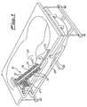
- Figure 1 is an overall schematic perspective view of the bathtub according to the invention;
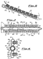
- Figure 2 is a view in overall longitudinal section of a preferred embodiment of a rotating distributor which performs hydromassaging of the back; .
- Figure 3 is a plan view of the distributor according to Figure 2;
- Figure 4 is a view of said distributor along the section IV-IV of Figure 3;
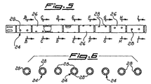
- Figure 5 is a side view, partially cut-away, of a supply duct of the rotating distributor according to Figure 2;
- Figure 6 illustrates a series of cross-sections (from B to I) of the duct according to Figure 5;
- Figure 7 illustrates schematically application of the rotating distributor according to Figure 2 to the backrest of the bath.
-
- With reference first of all to Figures 1 to 6, a description will now be given, by way of a non-limiting example, of the first embodiment of the bathtub according to the invention.
- Only the backrest portion of the tub is shown since it is the only part which is of interest for the purposes of understanding the present invention. The remainder of the bathtub, whilst being provided with other devices for hydromassaging, is not shown since it is known per se.
- The backrest, denoted overall by 10, has two series of vents or
nozzles 12 for delivering a liquid under pressure, such as water for example. - The
nozzles 12 of each of the two series are aligned in a direction substantially parallel to the longitudinal median axis of thebackrest 10 and the two series ofnozzles 12 are parallel to each other and are composed of an equal number ofnozzles 12 which are equidistant with. respect to each other. - More precisely the
nozzles 12 of each series are mounted in pairs, as described in more detail below, on the upper side, i.e. on the side where thebackrest 10 of the bath is located, ofchambers 14 formed longitudinally in two parallel and symmetrical rows with respect to a composite centrallongitudinal duct 16 on two tubular portions denoted overall by 18a and 18b, respectively. As can be noted in particular from the cross-section of the assembly described here, theexternal wall 16a of theduct 16 and theportions 18a, 18b are formed as one piece. - Advantageously, therefore, this assembly may be made of plastic and hence be obtained simply by means of moulding with a significant reduction in costs.
- It can also be appreciated from the longitudinal section described above that, with the same moulding operation, the
chambers 14 of each row are separated from each other since, between each pair ofnozzles 12, the walls of thetubular portions 18a and 18b are folded back in a U-shape against one other on the three sides which extend from thecentral duct 16, thereby defining and separating between them thechambers 14 of each row. - The
chambers 14 which are located opposite one another symmetrically with respect to the compositecentral duct 16 may, however, assume two different and separate operating conditions.. They may, in fact, be respectively separated from one another or in communication with one another depending on the configuration assumed by the compositecentral duct 16 which, as will be explained below, performs the important function of a rotating distributor. In the second position, in particular, thechambers 14 in question are supplied simultaneously with liquid under pressure by the composite central duct or rotatingdistributor 16, supplying in turn the two pairs ofnozzles 12 associated with them. - It is obvious that, instead of a pair of
nozzles 12 for eachchamber 14, only one or more than two of them could be provided, these being variations strictly equivalent to the embodiment illustrated and described herein by way of example. - The composite central duct or rotating
distributor 16 comprises, within saidexternal wall 16a, an essentiallycylindrical sleeve 20, the ends of which are arranged in a fixed position in suitable seats provided at the ends of thetubular portions 18a, 18b. - The
sleeve 20 is open at the ends, into one of which the liquid under pressure coming from aknown supply pump 27 connected inside the bath via aduct 29 is introduced. - The
sleeve 20, at the other end, is connected to aduct 21 connected in turn to the waste outlet of the tub. Theduct 21 has inside it asolenoid valve 23 which is connected to a suitableelectronic sensor 25 for detecting the level of the liquid inside the bathtub, indicated by a broken line in the illustration, said sensor being fixed in any known manner on one of the external walls of the tub, for example the rear wall as shown in Figure 1. Thissensor 25, known per se, is calibrated so as to emit a control signal for opening thesolenoid valve 23 when the level of water inside the tub, during its emptying at the end of the hydromassage, has reached a predetermined minimum value. This value, for example, corresponds substantially to the height at which thelower delivery nozzles 12 are located with respect to the bottom of the bathtub. - The means described above, which allow the rotating distributor to be emptied entirely, prevent stagnation of the liquid in the said distributor, which is particularly damaging if the tub is not used for a long period of time.
- At the inlet to the
chambers 14, thesleeve 20 is provided with openings 22 (Figure 4) which allow the liquid under pressure to flow inside said chambers. According to one of the particularly advantageous features of the bathtub according to the invention, by means of asuitable supply duct 24 arranged inside thesleeve 20, the liquid under pressure is introduced in succession into each pair ofchambers 14 located opposite one another, i.e. in communication with each other as described above, in one direction or in the opposite direction. - The
abovementioned supply duct 24, which can be seen more clearly in Figures 5 and 6, formed by a tubular body of a length substantially equal to that of theexternal sleeve 20 on which there is formed a plurality ofholes 28 which are suitably offset with respect to one another and which allow thechambers 14 to be supplied in sequence with liquid under pressure, as explained above. - More precisely, the
holes 28 are grouped together, in the example of embodiment considered, in fours onportions 26 of equal length of theduct 24. The fourholes 28 of eachportion 26 are arranged in pairs in a diametral plane, i.e. are arranged at 180°, while the holes of eachportion 26 with respect to the preceding portion are offset at a predefined and constant angle, generally an acute angle. In this way theholes 28 are distributed over theduct 24 substantially in two helices. - In this situation it is obvious that, by rotating the
duct 24, theholes 28 will gradually be positioned in succession opposite theopenings 22 of thesleeve 20, thus allowing the liquid under pressure to pass correspondingly from a pair ofopposite chambers 14 to the next pair, and so on as far as the last pair, thus supplying all thenozzles 12. The order in which these latter are activated depends on the direction of rotation of theduct 24 and, in order to obtain the supply sequence mentioned earlier, it is sufficient to rotate said duct in one direction or the other. - The conditions in which the hydromassage is performed may be varied according to the user's needs and requirements. For example, increasing or reducing the speed of rotation of the
duct 24 causes, respectively, a reduction or increase in the duration of the supply sequence of thenozzles 12. - The force of the jets emerging from the
nozzles 12 may be varied for example by modifying the delivery of the liquid supply pump and this in particular enables one to increase or decrease the pressure with which the jets of said liquid reach the user's body. - According to a further advantageous feature of the invention, the assembly consisting of the composite central
longitudinal duct 16 and the twotubular portions 18a and 18b is fixed to the rear wall of thebackrest 10. A description is now given, by way of a non-limiting example, of a possible embodiment of this fixing system. The abovementioned assembly is first of all simply rested on the rear surface of the saidbackrest 10 of the tub, inside a suitable seat in the latter. - Then the
nozzles 12 are applied and fixed, through holes in saidbackrest 10, to thetubular portions 18a, 18b, thus fixing in this way the entire assembly to the bathtub. - In the example of embodiment considered, as can be seen more clearly in Figures 2 and 4, the walls of the
tubular portions 18a, 18b to which thenozzles 12 are applied, are provided withsleeve elements 30 of essentially cylindrical shape, the middle zone of which is sealingly fixed in any known manner to said walls. - The
portions 30a of thesleeve elements 30 which project outside thechambers 14 are threaded internally so that a corresponding threaded portion of the body of thenozzles 12 allows the latter to be screwed inside them. The top end of the body of thenozzles 12, i.e. the end arranged inside the tub, has anannular projection 12a which engages with the inner side of thebackrest 10, thereby providing the abovementioned fixing system since the end of theportions 30a of thesleeves 30 engages with the external surface of thebackrest 10. - On the end of the body of the
nozzles 12 opposite to the preceding end there are formed annular grooves, two in the example considered, inside each of which aseal 32 is mounted, said seal being provided so as to ensure a sealing action when the abovementioned end of thenozzles 12 is inserted into the portion 30b of thesleeve elements 30 which is located inside thechambers 14. The reason why two, or in somes cases more than two, seals 32 are provided is in order to ensure the sealing action in all circumstances, namely engagement of at least oneseal 32 in said portion 30b of thesleeves 30, independently of the wall thickness of thebackrest 10, which may vary from one bathtub to another. - It should obviously be remembered that the provision of
holes 28 on theduct 24 must be regarded solely as an example of embodiment since the same effects could be obtained by providing said duct with longitudinal eyelets, each of which would replace a pair ofholes 28, while, as regards the rest, these eyelets would be arranged, from oneportion 26 to the next, offset in the same manner as the holes in question. - The above description clearly illustrates the advantages of the bathtub according to the present invention.
- By providing the rotating distributor for carrying out the hydromassage of the back, the tub is simplified and the cost thereof reduced. In fact, the abovementioned distributor has made it possible to eliminate, or at least has entirely replaced, all the complex programming means provided in conventional bathtubs.
- The need for maintenance and the interruptions in operation have therefore been reduced to a minimum, if not eliminated, thereby making the bath particularly reliable.
- It is obvious, finally, that conceptually and structurally equivalent changes and/or modifications may be made to the bathtub according to the present invention without thereby departing from the scope of the appended claims.
Claims (13)
- A bath tub for hydromassage having a device for the hydromassage of the back of the user, comprising at least one series of nozzles (12) for delivering a liquid under pressure, each series of nozzles (12) being at least approximately parallel to the median axis of the backrest wall (10) of the tub, and a distributor adapted to feed - according to a predetermined sequence repeated cyclically for a predetermined period of time - the nozzles (12) with the liquid delivered by a supply source (27), the said distributor comprising :a first stationary member (20) which is connected to said source (27) and provided with openings (22) suitable to allow the liquid under pressure to flow from the the source (27) to the said nozzles (12) anda second member (24) which is arranged inside the said first member (20) and rotatably movable with respect to the same, the said second member being provided with a plurality of holes (28), whereby the rotating movement of the second member (24) with respect to the first member (20) causes the holes (28) provided in the second member to come into and out of alignment with the openings (22) provided in the first member (20), characterized in that :said distributor also comprises a duct or case (16) surrounding the said first member (20) and a plurality of chambers (14) on which the nozzles (12) are mounted in communication therewith,and in that the arrangement of the holes (28) provided in the said second member (24) is such that the rotation of the latter with respect to the said first member (20) causes the liquid under pressure to be introduced in succession into the various chambers (14) when the same holes (28) are aligned with the corresponding openings (22) provided in the first member (20) so as to obtain a sequence of liquid jets emerging from the nozzles (12).
- A bath tub for hydromassage according to claim 1, characterized in that the said chambers (14) are formed longitudinally in two parallel rows separated from one another on diametrally opposed tubular portions (18a, 18b) which are preferably formed as a one piece assembly with the external wall (16a) of the said duct or case (16).
- A bath tub for hydromassage according to claim 1 or 2, characterized in that said second member (24) is formed by a tubular body on which the holes (28) provided therein are offset with respect to one another.
- A bath tub for hydromassage according to claim 3, characterized in that said second member (24) consists of a plurality of portions (26), preferably of an equal length, on which the holes (28) are arranged diametrally opposed in at least one pair, the holes (28) of each of the said portions (26) being offset at a preferred and constant angle, generally an acute angle.
- A bath tub for hydromassage according to any of the preceding claims, characterized in that each series of nozzles (12) is composed of an equal number of nozzles which are equidistant with respect to each other.
- A bath tub for hydromassage according to any of the preceding claims, characterized in that each nozzle (12) is fixed to the associated chamber (14) by means of a sleeve element (30) provided on the same and comunicating therewith.
- A bath tub for hydromassage according to claim 6, characterized in that the said sleeve element (30), which is of essentially cylindrical shape, consists of a first portion (30a) projecting outside the chamber (14) for a threaded connection with a corresponding portion of the nozzle (12) and a second portion (30b) inside the chamber (14) for a sealed connection with another corresponding portion of the same nozzle (12).
- A bath tub for hydromassage according to any claim 2 to 7, characterized in that the assembly consisting of the said duct or case (16) and the said tubular portions (18a, 18b) is mounted and fixed externally to the rear wall of the backrest wall (10) so as to be fixed to the end of the nozzles (12) projecting from the external surface of the tub.
- A bath tub for hydromassage according to claim 7 or 8, characterized in that the said sealed connection of the second portion (30b) of the said sleeve (30) inside the chamber (14) to a corresponding portion of the nozzle (12) makes use of at least a couple of gaskets (32) longitudinally spaced from each other in order to ensure a proper sealing action independently of the thickness of the backrest (10).
- A bath tub for hydromassage according to any of the preceding claims, characterized in that the duration of the sequence with which the nozzles (12) are fed with the liquid by the distributor is determined by the speed of rotation of the said second member (24) with respect to the said first stationary member (20).
- A bath tub for hydromassage according to any of the preceding claims, characterized in that the said distributor is also connected to a duct (21) which is in turn connected to the waste outlet of the bath tub so as to be fully discharged from the residual liquid at the end of the usage.
- A bath tub for hydromassage according to claim 11, characterized in that valve means (23) are provided in the said duct (21) which are activated by sensing means (25) for detecting when the level of the liquid in the bath tub has reached a predetermined minimum value during the emptying at the end of the usage.
- A bath tub for hydromassage according to claim 12, characterized in that the said predetermined minimum value of the level of the liquid substantially corresponds to the height of the lowemost one of the nozzles (12) with respect to the bottom of the tub.
Applications Claiming Priority (2)
| Application Number | Priority Date | Filing Date | Title |
|---|---|---|---|
| ITPD930192A IT1263696B (en) | 1993-09-27 | 1993-09-27 | BATHTUB FOR WHIRLPOOL, IN PARTICULAR DORSAL WHIRLPOOL |
| ITPD930192 | 1993-09-27 |
Publications (2)
| Publication Number | Publication Date |
|---|---|
| EP0645133A1 EP0645133A1 (en) | 1995-03-29 |
| EP0645133B1 true EP0645133B1 (en) | 2002-12-11 |
Family
ID=11390449
Family Applications (1)
| Application Number | Title | Priority Date | Filing Date |
|---|---|---|---|
| EP94202732A Expired - Lifetime EP0645133B1 (en) | 1993-09-27 | 1994-09-22 | Hydromassage bath with a rotating distributor |
Country Status (7)
| Country | Link |
|---|---|
| EP (1) | EP0645133B1 (en) |
| JP (1) | JPH07148214A (en) |
| BR (1) | BR9403862A (en) |
| CA (1) | CA2132901A1 (en) |
| DE (1) | DE69431863T2 (en) |
| ES (1) | ES2185641T3 (en) |
| IT (1) | IT1263696B (en) |
Families Citing this family (7)
| Publication number | Priority date | Publication date | Assignee | Title |
|---|---|---|---|---|
| FR2734155B1 (en) * | 1995-05-19 | 1997-11-07 | Aubert Alain | HYDROTHERAPY DEVICE ESPECIALLY ADAPTABLE TO A SHOWER ENCLOSURE |
| DE202005019335U1 (en) * | 2005-12-10 | 2006-01-26 | Heuberger, Tobias | Device for supplying fluids to a tub |
| JP4646259B2 (en) * | 2008-07-22 | 2011-03-09 | 株式会社日本メディックス | Liquid massage device |
| JP4590488B2 (en) * | 2009-03-31 | 2010-12-01 | 株式会社日本メディックス | Liquid massage device |
| DE202010016928U1 (en) | 2010-12-23 | 2011-08-09 | Gunther Stolz | Therapy tub with a sloping back wall |
| CN106923716A (en) * | 2017-05-16 | 2017-07-07 | 吴为生 | Multifunctional bathtub |
| CN113081723B (en) * | 2021-03-30 | 2023-04-07 | 未来穿戴技术有限公司 | Massage control method, massage instrument and computer readable storage medium |
Family Cites Families (6)
| Publication number | Priority date | Publication date | Assignee | Title |
|---|---|---|---|---|
| DE1087761B (en) * | 1953-10-29 | 1960-08-25 | Burkhardt Hoffmann Dipl Ing | Device for generating migrating underwater pressure cushions in a tub |
| FR2364026A2 (en) * | 1976-09-13 | 1978-04-07 | Duclaux Jean Paul | Bath massager with cycles in direction of venous blood return - uses control of bath temp. according to heart beat of patient |
| FR2398851A1 (en) * | 1977-07-26 | 1979-02-23 | Nicollet Michel | Water distributor for massage bath - has distributor at low point to enable return water flow by gravity |
| ES285113Y (en) * | 1984-03-13 | 1986-09-01 | Conti Francesco | DEVICE FOR WHIRLPOOLS |
| FR2610519B1 (en) * | 1987-02-05 | 1990-02-23 | Gedouin Jean | HYDROMASSAGE TUB |
| GB8708377D0 (en) * | 1987-04-08 | 1987-05-13 | Stewart Products Ltd Leigh | Spa baths |
-
1993
- 1993-09-27 IT ITPD930192A patent/IT1263696B/en active IP Right Grant
-
1994
- 1994-09-22 DE DE69431863T patent/DE69431863T2/en not_active Expired - Lifetime
- 1994-09-22 EP EP94202732A patent/EP0645133B1/en not_active Expired - Lifetime
- 1994-09-22 ES ES94202732T patent/ES2185641T3/en not_active Expired - Lifetime
- 1994-09-26 BR BR9403862A patent/BR9403862A/en not_active Application Discontinuation
- 1994-09-26 CA CA002132901A patent/CA2132901A1/en not_active Abandoned
- 1994-09-27 JP JP6257562A patent/JPH07148214A/en active Pending
Also Published As
| Publication number | Publication date |
|---|---|
| JPH07148214A (en) | 1995-06-13 |
| ES2185641T3 (en) | 2003-05-01 |
| EP0645133A1 (en) | 1995-03-29 |
| BR9403862A (en) | 1995-05-30 |
| IT1263696B (en) | 1996-08-27 |
| DE69431863T2 (en) | 2003-09-04 |
| CA2132901A1 (en) | 1995-03-28 |
| DE69431863D1 (en) | 2003-01-23 |
| ITPD930192A1 (en) | 1995-03-27 |
| ITPD930192A0 (en) | 1993-09-27 |
Similar Documents
| Publication | Publication Date | Title |
|---|---|---|
| KR100401360B1 (en) | Water dispenser for washing machines | |
| US4382424A (en) | Automatic apparatus for cleaning dogs and similar animals | |
| CZ2005526A3 (en) | Machine and method for liquid injection | |
| KR940000125B1 (en) | Blower device of human local washer | |
| KR20160149675A (en) | Dishwasher and Method for controlling it | |
| EP0645133A1 (en) | Hydromassage bath with a rotating distributor | |
| KR100212427B1 (en) | Washing machine with jet nozzle assembly | |
| KR20060127261A (en) | Ink chamber cleaning method of printing unit and its system | |
| US3021863A (en) | Dispensing mechanism | |
| EP0500737A4 (en) | Detergent dispenser in a dishwashing machine | |
| US20230182153A1 (en) | Multipurpose shower head | |
| US7182090B2 (en) | System for cleaning components of a water retaining device, associated water retaining device, and water propulsion device for use therein | |
| US4823818A (en) | Dispensing device for washing products for a dishwashing machine | |
| KR102072936B1 (en) | Seat washing apparatus for sedentary toilet | |
| EP0034123A2 (en) | Automatic apparatus for cleaning dogs and similar animals | |
| JPS6467289A (en) | Method and apparatus for cleaning the inner wall surface of passageway | |
| JP4625835B2 (en) | Head / face cleaning device | |
| JPH10234598A (en) | Bath tub cleaning device | |
| JP4484973B2 (en) | Head / face cleaning device | |
| KR970010954B1 (en) | Hair wash | |
| KR0134839Y1 (en) | A shower water supply construction of a washing machine | |
| JP3473719B2 (en) | Spray nozzle | |
| JPH03158534A (en) | Warm water jet type limited part washer | |
| KR0114258Y1 (en) | Washing device for closets51 e 03 d 9/08 | |
| KR100461870B1 (en) | Detergent throwing device of washing machine |
Legal Events
| Date | Code | Title | Description |
|---|---|---|---|
| PUAI | Public reference made under article 153(3) epc to a published international application that has entered the european phase |
Free format text: ORIGINAL CODE: 0009012 |
|
| AK | Designated contracting states |
Kind code of ref document: A1 Designated state(s): DE ES FR GB IT |
|
| 17P | Request for examination filed |
Effective date: 19950915 |
|
| 17Q | First examination report despatched |
Effective date: 19970905 |
|
| GRAG | Despatch of communication of intention to grant |
Free format text: ORIGINAL CODE: EPIDOS AGRA |
|
| GRAG | Despatch of communication of intention to grant |
Free format text: ORIGINAL CODE: EPIDOS AGRA |
|
| GRAH | Despatch of communication of intention to grant a patent |
Free format text: ORIGINAL CODE: EPIDOS IGRA |
|
| GRAH | Despatch of communication of intention to grant a patent |
Free format text: ORIGINAL CODE: EPIDOS IGRA |
|
| GRAA | (expected) grant |
Free format text: ORIGINAL CODE: 0009210 |
|
| AK | Designated contracting states |
Kind code of ref document: B1 Designated state(s): DE ES FR GB IT |
|
| REG | Reference to a national code |
Ref country code: GB Ref legal event code: FG4D |
|
| REF | Corresponds to: |
Ref document number: 69431863 Country of ref document: DE Date of ref document: 20030123 |
|
| REG | Reference to a national code |
Ref country code: ES Ref legal event code: FG2A Ref document number: 2185641 Country of ref document: ES Kind code of ref document: T3 |
|
| ET | Fr: translation filed | ||
| PLBE | No opposition filed within time limit |
Free format text: ORIGINAL CODE: 0009261 |
|
| STAA | Information on the status of an ep patent application or granted ep patent |
Free format text: STATUS: NO OPPOSITION FILED WITHIN TIME LIMIT |
|
| 26N | No opposition filed |
Effective date: 20030912 |
|
| PGFP | Annual fee paid to national office [announced via postgrant information from national office to epo] |
Ref country code: ES Payment date: 20090928 Year of fee payment: 16 |
|
| PGFP | Annual fee paid to national office [announced via postgrant information from national office to epo] |
Ref country code: GB Payment date: 20090929 Year of fee payment: 16 |
|
| PGFP | Annual fee paid to national office [announced via postgrant information from national office to epo] |
Ref country code: DE Payment date: 20090929 Year of fee payment: 16 |
|
| PGFP | Annual fee paid to national office [announced via postgrant information from national office to epo] |
Ref country code: IT Payment date: 20090925 Year of fee payment: 16 |
|
| GBPC | Gb: european patent ceased through non-payment of renewal fee |
Effective date: 20100922 |
|
| PG25 | Lapsed in a contracting state [announced via postgrant information from national office to epo] |
Ref country code: IT Free format text: LAPSE BECAUSE OF NON-PAYMENT OF DUE FEES Effective date: 20100922 |
|
| REG | Reference to a national code |
Ref country code: FR Ref legal event code: ST Effective date: 20110531 |
|
| REG | Reference to a national code |
Ref country code: DE Ref legal event code: R119 Ref document number: 69431863 Country of ref document: DE Effective date: 20110401 |
|
| PG25 | Lapsed in a contracting state [announced via postgrant information from national office to epo] |
Ref country code: FR Free format text: LAPSE BECAUSE OF NON-PAYMENT OF DUE FEES Effective date: 20100930 Ref country code: DE Free format text: LAPSE BECAUSE OF NON-PAYMENT OF DUE FEES Effective date: 20110401 |
|
| PG25 | Lapsed in a contracting state [announced via postgrant information from national office to epo] |
Ref country code: GB Free format text: LAPSE BECAUSE OF NON-PAYMENT OF DUE FEES Effective date: 20100922 |
|
| PGFP | Annual fee paid to national office [announced via postgrant information from national office to epo] |
Ref country code: FR Payment date: 20091006 Year of fee payment: 16 |
|
| REG | Reference to a national code |
Ref country code: ES Ref legal event code: FD2A Effective date: 20111019 |
|
| PG25 | Lapsed in a contracting state [announced via postgrant information from national office to epo] |
Ref country code: ES Free format text: LAPSE BECAUSE OF NON-PAYMENT OF DUE FEES Effective date: 20100923 |