EP0645047B1 - Procede de fabrication des corps isolants - Google Patents
Procede de fabrication des corps isolants Download PDFInfo
- Publication number
- EP0645047B1 EP0645047B1 EP93913315A EP93913315A EP0645047B1 EP 0645047 B1 EP0645047 B1 EP 0645047B1 EP 93913315 A EP93913315 A EP 93913315A EP 93913315 A EP93913315 A EP 93913315A EP 0645047 B1 EP0645047 B1 EP 0645047B1
- Authority
- EP
- European Patent Office
- Prior art keywords
- yarn
- insulator
- fibres
- mould
- blocking
- Prior art date
- Legal status (The legal status is an assumption and is not a legal conclusion. Google has not performed a legal analysis and makes no representation as to the accuracy of the status listed.)
- Expired - Lifetime
Links
Images


Classifications
-
- H—ELECTRICITY
- H01—ELECTRIC ELEMENTS
- H01B—CABLES; CONDUCTORS; INSULATORS; SELECTION OF MATERIALS FOR THEIR CONDUCTIVE, INSULATING OR DIELECTRIC PROPERTIES
- H01B19/00—Apparatus or processes specially adapted for manufacturing insulators or insulating bodies
-
- B—PERFORMING OPERATIONS; TRANSPORTING
- B29—WORKING OF PLASTICS; WORKING OF SUBSTANCES IN A PLASTIC STATE IN GENERAL
- B29C—SHAPING OR JOINING OF PLASTICS; SHAPING OF MATERIAL IN A PLASTIC STATE, NOT OTHERWISE PROVIDED FOR; AFTER-TREATMENT OF THE SHAPED PRODUCTS, e.g. REPAIRING
- B29C70/00—Shaping composites, i.e. plastics material comprising reinforcements, fillers or preformed parts, e.g. inserts
- B29C70/04—Shaping composites, i.e. plastics material comprising reinforcements, fillers or preformed parts, e.g. inserts comprising reinforcements only, e.g. self-reinforcing plastics
- B29C70/28—Shaping operations therefor
- B29C70/30—Shaping by lay-up, i.e. applying fibres, tape or broadsheet on a mould, former or core; Shaping by spray-up, i.e. spraying of fibres on a mould, former or core
- B29C70/34—Shaping by lay-up, i.e. applying fibres, tape or broadsheet on a mould, former or core; Shaping by spray-up, i.e. spraying of fibres on a mould, former or core and shaping or impregnating by compression, i.e. combined with compressing after the lay-up operation
- B29C70/347—Shaping by lay-up, i.e. applying fibres, tape or broadsheet on a mould, former or core; Shaping by spray-up, i.e. spraying of fibres on a mould, former or core and shaping or impregnating by compression, i.e. combined with compressing after the lay-up operation combined with compressing after the winding of lay-ups having a non-circular cross-section, e.g. flat spiral windings
-
- B—PERFORMING OPERATIONS; TRANSPORTING
- B29—WORKING OF PLASTICS; WORKING OF SUBSTANCES IN A PLASTIC STATE IN GENERAL
- B29C—SHAPING OR JOINING OF PLASTICS; SHAPING OF MATERIAL IN A PLASTIC STATE, NOT OTHERWISE PROVIDED FOR; AFTER-TREATMENT OF THE SHAPED PRODUCTS, e.g. REPAIRING
- B29C70/00—Shaping composites, i.e. plastics material comprising reinforcements, fillers or preformed parts, e.g. inserts
- B29C70/04—Shaping composites, i.e. plastics material comprising reinforcements, fillers or preformed parts, e.g. inserts comprising reinforcements only, e.g. self-reinforcing plastics
- B29C70/28—Shaping operations therefor
- B29C70/40—Shaping or impregnating by compression not applied
- B29C70/42—Shaping or impregnating by compression not applied for producing articles of definite length, i.e. discrete articles
- B29C70/46—Shaping or impregnating by compression not applied for producing articles of definite length, i.e. discrete articles using matched moulds, e.g. for deforming sheet moulding compounds [SMC] or prepregs
- B29C70/465—Shaping or impregnating by compression not applied for producing articles of definite length, i.e. discrete articles using matched moulds, e.g. for deforming sheet moulding compounds [SMC] or prepregs and impregnating by melting a solid material, e.g. sheets, powders of fibres
-
- B—PERFORMING OPERATIONS; TRANSPORTING
- B29—WORKING OF PLASTICS; WORKING OF SUBSTANCES IN A PLASTIC STATE IN GENERAL
- B29C—SHAPING OR JOINING OF PLASTICS; SHAPING OF MATERIAL IN A PLASTIC STATE, NOT OTHERWISE PROVIDED FOR; AFTER-TREATMENT OF THE SHAPED PRODUCTS, e.g. REPAIRING
- B29C70/00—Shaping composites, i.e. plastics material comprising reinforcements, fillers or preformed parts, e.g. inserts
- B29C70/68—Shaping composites, i.e. plastics material comprising reinforcements, fillers or preformed parts, e.g. inserts by incorporating or moulding on preformed parts, e.g. inserts or layers, e.g. foam blocks
- B29C70/86—Incorporated in coherent impregnated reinforcing layers, e.g. by winding
- B29C70/865—Incorporated in coherent impregnated reinforcing layers, e.g. by winding completely encapsulated
-
- H—ELECTRICITY
- H01—ELECTRIC ELEMENTS
- H01B—CABLES; CONDUCTORS; INSULATORS; SELECTION OF MATERIALS FOR THEIR CONDUCTIVE, INSULATING OR DIELECTRIC PROPERTIES
- H01B17/00—Insulators or insulating bodies characterised by their form
- H01B17/02—Suspension insulators; Strain insulators
- H01B17/12—Special features of strain insulators
-
- B—PERFORMING OPERATIONS; TRANSPORTING
- B29—WORKING OF PLASTICS; WORKING OF SUBSTANCES IN A PLASTIC STATE IN GENERAL
- B29L—INDEXING SCHEME ASSOCIATED WITH SUBCLASS B29C, RELATING TO PARTICULAR ARTICLES
- B29L2031/00—Other particular articles
- B29L2031/34—Electrical apparatus, e.g. sparking plugs or parts thereof
- B29L2031/3412—Insulators
-
- Y—GENERAL TAGGING OF NEW TECHNOLOGICAL DEVELOPMENTS; GENERAL TAGGING OF CROSS-SECTIONAL TECHNOLOGIES SPANNING OVER SEVERAL SECTIONS OF THE IPC; TECHNICAL SUBJECTS COVERED BY FORMER USPC CROSS-REFERENCE ART COLLECTIONS [XRACs] AND DIGESTS
- Y10—TECHNICAL SUBJECTS COVERED BY FORMER USPC
- Y10T—TECHNICAL SUBJECTS COVERED BY FORMER US CLASSIFICATION
- Y10T428/00—Stock material or miscellaneous articles
- Y10T428/29—Coated or structually defined flake, particle, cell, strand, strand portion, rod, filament, macroscopic fiber or mass thereof
- Y10T428/2913—Rod, strand, filament or fiber
- Y10T428/2918—Rod, strand, filament or fiber including free carbon or carbide or therewith [not as steel]
-
- Y—GENERAL TAGGING OF NEW TECHNOLOGICAL DEVELOPMENTS; GENERAL TAGGING OF CROSS-SECTIONAL TECHNOLOGIES SPANNING OVER SEVERAL SECTIONS OF THE IPC; TECHNICAL SUBJECTS COVERED BY FORMER USPC CROSS-REFERENCE ART COLLECTIONS [XRACs] AND DIGESTS
- Y10—TECHNICAL SUBJECTS COVERED BY FORMER USPC
- Y10T—TECHNICAL SUBJECTS COVERED BY FORMER US CLASSIFICATION
- Y10T428/00—Stock material or miscellaneous articles
- Y10T428/29—Coated or structually defined flake, particle, cell, strand, strand portion, rod, filament, macroscopic fiber or mass thereof
- Y10T428/2913—Rod, strand, filament or fiber
- Y10T428/2929—Bicomponent, conjugate, composite or collateral fibers or filaments [i.e., coextruded sheath-core or side-by-side type]
-
- Y—GENERAL TAGGING OF NEW TECHNOLOGICAL DEVELOPMENTS; GENERAL TAGGING OF CROSS-SECTIONAL TECHNOLOGIES SPANNING OVER SEVERAL SECTIONS OF THE IPC; TECHNICAL SUBJECTS COVERED BY FORMER USPC CROSS-REFERENCE ART COLLECTIONS [XRACs] AND DIGESTS
- Y10—TECHNICAL SUBJECTS COVERED BY FORMER USPC
- Y10T—TECHNICAL SUBJECTS COVERED BY FORMER US CLASSIFICATION
- Y10T428/00—Stock material or miscellaneous articles
- Y10T428/29—Coated or structually defined flake, particle, cell, strand, strand portion, rod, filament, macroscopic fiber or mass thereof
- Y10T428/2913—Rod, strand, filament or fiber
- Y10T428/2933—Coated or with bond, impregnation or core
- Y10T428/2936—Wound or wrapped core or coating [i.e., spiral or helical]
-
- Y—GENERAL TAGGING OF NEW TECHNOLOGICAL DEVELOPMENTS; GENERAL TAGGING OF CROSS-SECTIONAL TECHNOLOGIES SPANNING OVER SEVERAL SECTIONS OF THE IPC; TECHNICAL SUBJECTS COVERED BY FORMER USPC CROSS-REFERENCE ART COLLECTIONS [XRACs] AND DIGESTS
- Y10—TECHNICAL SUBJECTS COVERED BY FORMER USPC
- Y10T—TECHNICAL SUBJECTS COVERED BY FORMER US CLASSIFICATION
- Y10T428/00—Stock material or miscellaneous articles
- Y10T428/29—Coated or structually defined flake, particle, cell, strand, strand portion, rod, filament, macroscopic fiber or mass thereof
- Y10T428/2913—Rod, strand, filament or fiber
- Y10T428/2933—Coated or with bond, impregnation or core
- Y10T428/2938—Coating on discrete and individual rods, strands or filaments
-
- Y—GENERAL TAGGING OF NEW TECHNOLOGICAL DEVELOPMENTS; GENERAL TAGGING OF CROSS-SECTIONAL TECHNOLOGIES SPANNING OVER SEVERAL SECTIONS OF THE IPC; TECHNICAL SUBJECTS COVERED BY FORMER USPC CROSS-REFERENCE ART COLLECTIONS [XRACs] AND DIGESTS
- Y10—TECHNICAL SUBJECTS COVERED BY FORMER USPC
- Y10T—TECHNICAL SUBJECTS COVERED BY FORMER US CLASSIFICATION
- Y10T428/00—Stock material or miscellaneous articles
- Y10T428/29—Coated or structually defined flake, particle, cell, strand, strand portion, rod, filament, macroscopic fiber or mass thereof
- Y10T428/2913—Rod, strand, filament or fiber
- Y10T428/2933—Coated or with bond, impregnation or core
- Y10T428/2964—Artificial fiber or filament
- Y10T428/2967—Synthetic resin or polymer
- Y10T428/2969—Polyamide, polyimide or polyester
-
- Y—GENERAL TAGGING OF NEW TECHNOLOGICAL DEVELOPMENTS; GENERAL TAGGING OF CROSS-SECTIONAL TECHNOLOGIES SPANNING OVER SEVERAL SECTIONS OF THE IPC; TECHNICAL SUBJECTS COVERED BY FORMER USPC CROSS-REFERENCE ART COLLECTIONS [XRACs] AND DIGESTS
- Y10—TECHNICAL SUBJECTS COVERED BY FORMER USPC
- Y10T—TECHNICAL SUBJECTS COVERED BY FORMER US CLASSIFICATION
- Y10T428/00—Stock material or miscellaneous articles
- Y10T428/30—Self-sustaining carbon mass or layer with impregnant or other layer
Definitions
- the present invention relates to a method of making composite, for example electrically insulating, articles, including electrical insulators per se, and in particular to reinforced polymeric insulators.
- the invention is preferably concerned with articles that perform a solely insulating function, and the ensuring description, for convenience, will relate mainly thereto, it is to be understood that in general the composite, for example, electrically insulating articles may also or alternatively perform other functions.
- the article may be a surge arrester, which for most of its time acts as an insulator but which, on the application of an over-voltage thereto, becomes conducting, in order to divert a surge of electrical power, from a lightning strike on associated electrical equipment for example, to earth.
- the invention relates to composite articles whether electrically insulating or conductive.
- Electrical insulators for use at voltages in excess of about 1kV, and typically at 24kV can be formed from (i) porcelain, which has good electrical properties but is heavy and brittle, thus having low resistance to vandalism; (ii) glass fibre rod impregnated with an epoxy resin, which is of lighter weight but generally has inferior electrical performance to porcelain in outdoor applications, or must be environmentally sealed; or (iii) solid polymeric material, which combines the advantages of light weight and good electrical performance but has poorer load bearing properties. Furthermore, polymeric tubing and/or sheds (annular extensions) may be added to porcelain or glass fibre rods, or incorporated into polymeric insulator, for enhanced performance.
- the present invention provides a method of making a composite article, the article comprising yarn enclosed within outer fusible material, wherein
- yarn is used to mean a plurality of fibres, which may be mono- or multi- filament fibres, and is considered to be synonymous with strand, tow, thread or tape.
- thermoplastic a material that flows on becoming hot and which either cures under the influence of the heat or solidifies on cooling, and thus includes thermoplastic and thermosetting materials.
- the method of the invention thus provides blocking (against moisture transmission) of the high strength fibres in a single process that also forms the enclosing insulating body.
- the pressure of the insulating material entering the mould assists in driving air out of the interstices between the fibres, and its temperature causes the blocking material to melt and to flow completely around the fibres.
- the blocking material is expected to be molten at the temperature at which the outer insulating material flows into the mould, its complete encapsulation by the latter material ensures that the blocking material remains completely around the high strength fibres, formed for example into a tube, rod or loop.
- such blocking will thus prevent flow of moisture through the article and also prevent electrical tracking taking place between the inner structural core and the outer casing material of the article.
- Such a manufacturing process allows the article to be made using a single moulding process at a comparatively low cost.
- an electrical insulator preferably of elongate configuration, comprising a substantially closed, preferably elongate, loop of high strength, preferably insulating, yarn of fibres that are blocked against the transmission of moisture therealong, the loop extending around means arranged for the attachment of electrical and mechanical connections to the insulator, and the loop being enclosed, preferably embedded, within insulating polymeric, and preferably substantially electrically non-tracking (in accordance with ASTM D2303), material that preferably forms an outer surface of the insulator.
- Multi-filament glass fibres are preferred as the strength member of the yarn, but other high strength fibres, such as carbon, or aramid fibres, for example those sold under the trademark KEVLAR, may also be used.
- Each multi-filament fibre, as well as containing a plurality of glass filaments may also contain the blocking material, preferably in staple or continuous or other fibre form, or in powder form or as a coating on or within the strength fibres.
- the structure and blocking of such fibres, which forms part of the present invention, is disclosed in EP-A-0 324 630 (Raychem) and its corresponding patent publications in other countries.
- the fibres may be monofilament. In either case, blocking may avoid or reduce voids between filaments of the yarn and a surrounding polymeric material, such as the outer coating material of the insulator.
- the blocking of the or each filament of the yarn may be enhanced by the provision of blocking material around the or each filament.
- the outer fusible and/or blocking material advantageously comprises a thermoplastic or a curable material, preferably polypropylene, polyethylene, silicone, polyamides, polyethyleneteraphthalate, polybutyleneteraphthalate, polyesters, acrylics, ethylene-vinyl-acetate copolymer, polyacrylonitrile, polymethylmethacrylate or low strength glass.
- a thermoplastic or a curable material preferably polypropylene, polyethylene, silicone, polyamides, polyethyleneteraphthalate, polybutyleneteraphthalate, polyesters, acrylics, ethylene-vinyl-acetate copolymer, polyacrylonitrile, polymethylmethacrylate or low strength glass.
- the fibrous blocking material may be substantially axially aligned with the high strength fibres, may be wrapped helically therearound, or may be interwoven therewith to form a two- or three-dimensional mat.
- an elongate insulator for example, so produced would have high tensile strength, and in the latter case, an insulator for use in cantilver applications could be produced.
- the blocking material may be a powder or a coating deposited on or within the filaments of the high strength fibres.
- the outer electrically insulating material advantageously comprises a polymeric material, preferably of a polyethylene or of a silicone polymer.
- EP-A-0 265 265 relates to an article incorporating fibres and discloses the blocking of such fibres against moisture (e.g. water or other liquid) wicking therealong.
- moisture e.g. water or other liquid
- the yarn is wound repeatedly, say of the order of two or three hundred times, around two mandrels that are spaced apart, transversely to the direction of winding, at the required separation of the end terminals of the insulator, forming an elongate loop of rounded rectangular configuration that is substantially closed, that is to say it is formed from a single yarn, which may itself comprise many filaments, and thus has only two exposed yarn ends.
- the yarn, held under tension between the mandrels, is then transferred to a mould for forming the polymeric insulating material therearound to provide the appropriately-shaped outer surface of the insulator - typically comprising one or more laterally-extending polymeric sheds.
- the blocking materials melts, or at least softens, so as to be urged between and around the glass filaments to form blocking along the path of the loop, at least at one point therealong and preferably throughout its entire length.
- polymeric insulated component is removed from the mould.
- the mandrels can now be removed.
- the mandrels are envisaged to be rigidly secured together during cooling and/or curing to maintain their spacing apart. However, particularly when the insulator is to be used as a tension insulator, it may not be necessary for the blocked insulator to be rigid.
- electrical and mechanical connection end fittings may be provided as part of the mandrels, which may or may not be electrically conductive, and would thus subsequently remain in position.
- the end fittings can be secured in position in the single operation that effects blocking of the fibres and also moulding of the insulating body of the insulator.
- the mandrel or end fittings as appropriate, which may be formed as a rod or tube or other suitable configuration, are advantageously concave at their outer surfaces, which receive the yarn thereover, to assist in the lateral retention of the yarn during the winding operation.
- the end fittings may be of metal, but any other suitable conductive material, such as high strength conductive polymer, may be used. Alternatively these components may be electrically insulating.
- the polymeric material can be chosen to suit the application, but may typically be high density polyethylene or similar material, preferably containing a track-reducing filler, such as alumina trihydrate, to reduce the tendency of forming carbonaceous paths formed, in operation, from the flow of leakage current along the outer surface of the insulator.
- a track-reducing filler such as alumina trihydrate
- Suitable materials are disclosed for example in GB-A-1 337 951, GB-A-1 337 952 and GB-A-1 590 723 (Raychem).
- Other materials, such as thermosets for example, may also be used.
- the polymeric material and/or the yarn may be cross-linked.
- the fibrous loop is completely encased within, and bonded to, the outer polymeric material, preferably such that the insulator is substantially void free.
- the end fittings which may be short lengths of metal tube that extend transversely to the (major axis of the elongate) loop, lie within the loop such that great mechanical strength is provided - typically the insulator can withstand an axial loading of 70kN, which is the minimum requirement for its use as a 24kV tension insulator.
- the end fittings advantageously are so shaped as to spread out any electrical or mechanical stress thereon, for example so as to minimise the likelihood of fracturing the loop that is wound therearound.
- an oval or a pear shape is preferred to a circular cross-section, and preferably exhibits a low coefficient of friction with respect to the loop.
- Surfaces of the end fittings are preferably also rounded so as to avoid any points at which damaging electrical activity can occur.
- the term "insulator” as used herein refers to an article that performs an insulating function. It is envisaged that such an article may not perform an insulating function for the whole of its lifetime and/or may perform a function that is not solely insulating. In this respect, it is envisaged that the article may be associated with, for example may encompass within its insulating polymeric material, other functional components. For example the components may be varistors such as metal oxide components that allow the article to operate under certain conditions as a surge arrester to provide protection against lightning strikes or other over-voltages applied to associated equipment.
- a pair of metal bobbins 2 are formed from a short length of metal tube whose outer surface, at least on one side is made concave.
- the bobbins 2 are held apart at the required separation of the end fittings of the completed insulator by means not shown.
- a single multi-filament glass fibre hybrid yarn containing polypropylene blocking material is wound under tension around the bobbins 2, to engage the concave surfaces thereof, for approximately two hundred turns, to form an elongate loop 4 of rounded rectangular configuration.
- the resulting configuration is similar to that of a fan belt extending around two pulleys.
- the loop 4 comprises strength filaments of glass together with blocking filaments of polypropylene.
- the loop would be of length 200 mm, width 17 mm (ie. the length of the concave portion of the tubular metal bobbins 2), and a thickness 3 mm.
- the loop 4 still under tension, is then transferred to an injection mould (not shown).
- the mould is evacuated and heated to remove air trapped within the yarn, and non-tracking insulating polymeric material 6 is injected at a temperature of about 125°C into the 200°C mould at a pressure of about 2000psi.
- the blocking filaments of the fibre forming the loop 2 melt and flow so as completely to encase the glass components and to fill the interstices therebetween, thus forming a rigid, moisture-blocked loop, and the polymeric material subsequently cools and/or cures.
- the polymeric material 6 is arranged to form the outer surface of the insulator.
- the mould is arranged to provide a plurality of sheds 8 of different radial dimensions. From Figure 2, it can be seen that the polymeric material extends completely around the outside of the loop 4 and also over its inner surface. Cut outs 10 are provided to reduce the weight, and also cost (due to less material 6 being used) of the insulator, and also to enhance the impedance to the flow of surface leakage currents therealong.
- the metal bobbins 2 remain in position in the finished insulator, and serve electrically to connect the insulator under tension to suitable electrical equipment.
- the strength fibres of the cores of the insulator of the present invention are shown and discussed as forming a straight loop, it is envisaged that the loop could be formed with a cross over during the filament winding step. Also, the loop could be twisted, once or a plurality of times, for example to form a tightly twisted configuration prior to insertion into the mould.
- a pair of spaced-apart, elongate metal rod mandrels 20, 22 with a continuous single glass fibre hybrid yarn 24 having blocking material associated therewith wound in helical configuration therearound are fed into a hopper (not shown) that delivers hot outer insulating polymeric material 26.
- a hopper not shown
- the yarn 24 becomes blocked against moisture transmission therealong and the yarn 24 and rods 20, 22 become completely encapsulated by the polymeric material 26.
- discrete blocked insulators can be cut to length by cuts transversely to the direction A to give an insulator of substantially uniform transverse dimension x.
- Sheds may then be added discretely, or by moulding in place, or by recovering a shedded tubular part therearound, thereby to provide an outer configuration as shown in Figure 1.
- the insulation of the fibre-wound end fittings may be provided by two materials.
- An inner, relatively inexpensive material may be selected to have properties that facilitate blocking of the filaments of the yarn, and a compatible outer material may be selected to have good electrical surface properties, such as high resistance to the formation of conductive tracks therealong.
- the fibrous loop used in the insulator may alternatively be formed as a braid, weave or knit providing a band, which may be slit to provide two or more loops of the required transverse dimension.
- the continuous yarn would be arranged to extend in the direction in which, in use as a tension insulator for example, tension would be applied to the insulator.
- end fittings and or interconnections two or more of the insulators could be joined together to form a chain.
- end fittings could be designed so as directly to interlock with one another, or a connecting link or other device could be provided.
- Such an extended insulator would then be suitable for operation at higher voltages.
- a single yarn loop 30 is shown extending around one of two metal eyelets 32, which ultimately will form the end fittings of the insulator.
- the yarn 30 extends between the two eyelets in a twisted configuration, whilst in Figure 5b, a free end of the fibre 30 is secured to an adjacent yarn portion by a crimp 34.
- Outer polymeric material is subsequently applied to provide insulation and to produce and/or enhance the blocking of the yarn, as hereinbefore described.
- FIG. 6 there is shown a stack of five zinc oxide varistor blocks 40 sandwiched between two metal terminals 42.
- a loop of a single yarn 44 extends around the blocks 40 and terminals 42 to retain them in axial compression.
- Outer polymeric insulation material 46 encapsulates the yarn 44 terminals 42 and blocks 40 completely, thereby to provide a shedded insulator arrangement that acts as a surge arrester having a blocked single yarn strength member 44.
- the polymeric material may be arranged to provide for venting from the varistor blocks 40 of any gas generated during their operation as a surge arrester, whilst maintaining complete encapsulation of the blocked loop 44.
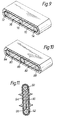
- Figure 7 shows an end portion of a surge arrester before its polymeric encapsulation, in which a metal terminal 50 is of semicylindrical configuration having a central connecting stud 52 that ultimately will project beyond the polymer.
- Two closed loops 54 of yarn are wrapped around respective shoulders of the terminal 50, and extends so as likewise to engage a corresponding terminal (not shown) at an opposite end of the arrester.
- One varistor block 56 is indicated.
- the loops 54 act as strength members to hold a stack of blocks 56 in compression between the two terminals 50.
- Figure 8 shows a cut away plan view of a modified surge arrester, in which two single loops of yarn 60, 62 overlap each other in cruciform shape as they extend over an end fitting (not shown) of a surge arrester, in similar manner to the single loop arrangement shown in Figure 6.
- the blocked loops 60, 62 are shown encapsulated in insulating polymeric material 64.
- the insulator of the present invention may be used as a support and/or guide member for additional lines such as power and telecommunication conductors, or for other wiring.
- the closed yarn loop 70 is disposed around two end mandrels 72, 74 and blocked and embedded within polymeric insulation material 76 in the manner described hereinbefore.
- a further hole is defined by an intermediate mandrel 78.
- the mandrels 72, 74 and 78 may, but need not be electrically conductive. Supply lines may then be arranged to pass through respective ones of the mandrels.
- the apertures 10 in the polymeric insulating material 6 of the embodiment of Figures 1 to 3 may also be used for this purpose.
- the mandrels 72, 74, 78 or the apertures 10 are thus seen to support supply lines extending therethrough, and keep them spaced apart and insulated (where necessary) from each other.
- Figure 10 shows a modification of the insulator of Figure 9, in which two closed loops 80, 82 of yarn are employed, in place of the single loop of Figure 9, around respective pairs of three mandrels 84, 86, 88.
- the loops extend in substantially the same plane as each other.
- the single loop 70 may be formed into a figure-of-eight between the mandrels 72 and 74, thus being more closely wound around the intermediate mandrel 78, and achieving a result similar to that of Figure 10.
- Figure 11 shows an insulator arrangement that is modified so as to include a rigid axial member that allows the insulator to be used in compression as well as in tension.
- a ceramic rod 90 has a mandrel 92 secured to each end thereof.
- a closed single loop 94 of yarn is then applied around the mandrels 92, and outer insulating material 96 applied therearound in the manner hereinbefore described.
- This insulator thus has tensile strength provided by the loop 94 and compressive strength provided by the rod 90, thereby providing a versatile component, for use as an aerial insulator on power cable systems for example.
Landscapes
- Engineering & Computer Science (AREA)
- Composite Materials (AREA)
- Mechanical Engineering (AREA)
- Chemical & Material Sciences (AREA)
- Insulators (AREA)
- Insulating Bodies (AREA)
- Laminated Bodies (AREA)
- Organic Insulating Materials (AREA)
- Yarns And Mechanical Finishing Of Yarns Or Ropes (AREA)
- Waveguide Aerials (AREA)
- Inorganic Insulating Materials (AREA)
- Crystals, And After-Treatments Of Crystals (AREA)
- Cold Cathode And The Manufacture (AREA)
- Optical Couplings Of Light Guides (AREA)
- Electron Sources, Ion Sources (AREA)
- Nonwoven Fabrics (AREA)
Claims (11)
- Procédé pour fabriquer un article composite, l'article comportant un fil (24) enfermé dans un matériau fusible extérieur (6, 26, 46, 64, 76, 96), dans lequel(i) le fil (24), comportant une fibre hautement résistante et un matériau de blocage fusible, est disposé dans un moule, et(ii) le matériau fusible extérieur (6, 26, 46, 64, 76, 96) est introduit dans le moule à l'état fondu, la température du matériau fusible extérieur (6, 26, 46, 64, 76, 96) étant au moins égale à, et de préférence au-dessus de, la température à laquelle le matériau de blocage fond, pour provoquer ainsi la fonte du matériau de blocage entre et autour des fibres résistantes du fil (24) afin de contenir complètement les fibres dedans, et de telle sorte que le fil bloqué soit complètement contenu dans le matériau fusible extérieur (6, 26, 46, 64, 76, 96).
- Procédé selon la revendication 1, dans lequel le matériau fusible extérieur (6, 26, 46, 64, 76, 96) et/ou le matériau de blocage comprend un matériau thermoplastique ou durcissable, de préférence du polypropylène, du polyacrylonitrile, du polyméthylméthacrylate, du polyéthylène, de la silicone, du polyéthylène-téréphtalate, du polybutylène-téréphtalate, un copolymère éthylène acétate de vinyle, ou du verre à faible résistance.
- Procédé selon la revendication 1 ou la revendication 2, dans lequel le fil (24) comprend des fibres de verre, de carbone ou d'aramide haute résistance.
- Procédé selon l'une quelconque des revendications précédentes, dans lequel le matériau fusible extérieur (6, 26, 46, 64, 76, 96) est électriquement isolant et est sensiblement résistant aux courants de fuite, conformément à ASTM D2303.
- Procédé selon l'une quelconque des revendications précédentes, dans lequel le matériau de blocage comprend des fibres qui sont enroulées autour ou entrelacées avec les fibres haute résistance du fil (24).
- Procédé selon l'une quelconque des revendications précédentes, dans lequel le fil (24) est tendu en une boucle (4, 30, 44, 54, 60, 62, 70, 80, 82, 94) qui est enroulée une ou plusieurs fois autour de deux éléments de support espacés (2, 20, 22, 32, 42, 50, 72, 74, 78, 84, 86, 88, 92) avant d'être introduite dans le moule.
- Procédé selon l'une quelconque des revendications 1 à 5, dans lequel le fil (24) est disposé de manière unidirectionnelle ou multidirectionnelle afin de former une tige ou un tube.
- Procédé selon l'une quelconque des revendications précédentes, dans lequel l'article est formé comme un isolateur électrique allongé, le fil (24) est sensiblement non conducteur, et les éléments de support servent d'éléments de support de charge pour connecter l'isolateur dans un circuit électrique.
- Procédé selon la revendication 8, dans lequel l'isolateur contient un ou plusieurs blocs de varistances (40, 56), fonctionnant ainsi comme un limitateur de surtension.
- Procédé selon l'une quelconque des revendications précédentes, dans lequel on fait le vide dans le moule à la suite du placement du fil (24) et avant l'introduction du matériau fusible extérieur (6, 26, 46, 64, 76, 96).
- Article isolant électriquement, comprenant un isolateur ou limitateur de surtension, fabriqué selon un procédé conforme à l'une quelconque des revendications précédentes.
Applications Claiming Priority (7)
| Application Number | Priority Date | Filing Date | Title |
|---|---|---|---|
| GB929212190A GB9212190D0 (en) | 1992-06-09 | 1992-06-09 | Insulators |
| GB9212190 | 1992-06-09 | ||
| GB929214492A GB9214492D0 (en) | 1992-07-08 | 1992-07-08 | Insulators |
| GB9214492 | 1992-07-08 | ||
| GB929214967A GB9214967D0 (en) | 1992-07-14 | 1992-07-14 | Insulators |
| GB9214967 | 1992-07-14 | ||
| PCT/GB1993/001210 WO1993026016A1 (fr) | 1992-06-09 | 1993-06-08 | Corps isolants |
Publications (2)
| Publication Number | Publication Date |
|---|---|
| EP0645047A1 EP0645047A1 (fr) | 1995-03-29 |
| EP0645047B1 true EP0645047B1 (fr) | 1997-04-09 |
Family
ID=27266233
Family Applications (1)
| Application Number | Title | Priority Date | Filing Date |
|---|---|---|---|
| EP93913315A Expired - Lifetime EP0645047B1 (fr) | 1992-06-09 | 1993-06-08 | Procede de fabrication des corps isolants |
Country Status (13)
| Country | Link |
|---|---|
| US (1) | US5725952A (fr) |
| EP (1) | EP0645047B1 (fr) |
| JP (1) | JP3542593B2 (fr) |
| KR (1) | KR100271531B1 (fr) |
| AT (1) | ATE151562T1 (fr) |
| AU (1) | AU673676B2 (fr) |
| CA (1) | CA2136995C (fr) |
| DE (1) | DE69309678T2 (fr) |
| FI (1) | FI113415B (fr) |
| MX (1) | MX9303451A (fr) |
| NO (1) | NO310325B1 (fr) |
| TW (1) | TW224533B (fr) |
| WO (1) | WO1993026016A1 (fr) |
Families Citing this family (5)
| Publication number | Priority date | Publication date | Assignee | Title |
|---|---|---|---|---|
| US9155544B2 (en) | 2002-03-20 | 2015-10-13 | P Tech, Llc | Robotic systems and methods |
| ATE477578T1 (de) * | 2003-04-10 | 2010-08-15 | Siemens Ag | Schlingenisolator |
| DE10316554B3 (de) * | 2003-04-10 | 2005-02-17 | Siemens Ag | Schlingenisolator |
| US7075406B2 (en) * | 2004-03-16 | 2006-07-11 | Cooper Technologies Company | Station class surge arrester |
| KR101697182B1 (ko) * | 2014-12-31 | 2017-01-17 | 한덕환 | 전선용 애자 |
Family Cites Families (11)
| Publication number | Priority date | Publication date | Assignee | Title |
|---|---|---|---|---|
| US4032383A (en) * | 1975-11-04 | 1977-06-28 | Mcdonnell Douglas Corporation | Fiber insertion device for continuous 3d foaming machine and method |
| DE3200063C2 (de) * | 1982-01-04 | 1984-06-28 | Breco Kunststoffverarbeitungs-Gesellschaft mbH & Co KG, 4952 Porta Westfalica | Verfahren zur Herstellung eines armierten Zahnriemens mit Gewebeauflage |
| GB8300220D0 (en) * | 1983-01-06 | 1983-02-09 | Raychem Ltd | Arrangement for enclosing substrates |
| FR2576076B1 (fr) * | 1985-01-11 | 1988-12-09 | David Jean Charles | Procede pour la confection d'attaches d'extremites ou de jonction dielectriques, legeres et de faible encombrement sur cordes en fibres aramides et la realisation de leurs composants |
| US5389442A (en) * | 1988-07-11 | 1995-02-14 | At&T Corp. | Water blocking strength members |
| ATE92677T1 (de) * | 1988-12-16 | 1993-08-15 | Rxs Schrumpftech Garnituren | Laengsgeteilte kabelmuffe mit flexibler umhuellung und halbzeug zur herstellung einer solchen kabelmuffe. |
| AU4488889A (en) * | 1988-12-30 | 1990-08-01 | Edwin R. Peterson | Miniature electric cable |
| JPH02248225A (ja) * | 1989-03-22 | 1990-10-04 | Ngk Insulators Ltd | モールド成形型 |
| DE3930496A1 (de) * | 1989-09-12 | 1991-03-21 | Reinshagen Kabelwerk Gmbh | Elektrische leitung mit zugfestem element |
| GB8923408D0 (en) * | 1989-10-17 | 1989-12-06 | Raychem Ltd | Electrical insulator |
| SE501855C2 (sv) * | 1990-11-19 | 1995-06-06 | Skf Ab | Gjutgods med ingjuten armering, samt förfarande för framställning av ett sådant gjutgods |
-
1993
- 1993-06-08 DE DE69309678T patent/DE69309678T2/de not_active Expired - Fee Related
- 1993-06-08 KR KR1019940704536A patent/KR100271531B1/ko not_active IP Right Cessation
- 1993-06-08 AU AU43430/93A patent/AU673676B2/en not_active Ceased
- 1993-06-08 EP EP93913315A patent/EP0645047B1/fr not_active Expired - Lifetime
- 1993-06-08 CA CA002136995A patent/CA2136995C/fr not_active Expired - Fee Related
- 1993-06-08 US US08/351,279 patent/US5725952A/en not_active Expired - Fee Related
- 1993-06-08 TW TW082104543A patent/TW224533B/zh active
- 1993-06-08 WO PCT/GB1993/001210 patent/WO1993026016A1/fr active IP Right Grant
- 1993-06-08 JP JP50125794A patent/JP3542593B2/ja not_active Expired - Fee Related
- 1993-06-08 AT AT93913315T patent/ATE151562T1/de not_active IP Right Cessation
- 1993-06-09 MX MX9303451A patent/MX9303451A/es unknown
-
1994
- 1994-12-07 NO NO19944724A patent/NO310325B1/no unknown
- 1994-12-08 FI FI945766A patent/FI113415B/fi not_active IP Right Cessation
Also Published As
| Publication number | Publication date |
|---|---|
| EP0645047A1 (fr) | 1995-03-29 |
| NO944724D0 (no) | 1994-12-07 |
| NO310325B1 (no) | 2001-06-18 |
| AU673676B2 (en) | 1996-11-21 |
| FI945766A (fi) | 1994-12-08 |
| CA2136995A1 (fr) | 1993-12-23 |
| JPH07507733A (ja) | 1995-08-31 |
| AU4343093A (en) | 1994-01-04 |
| WO1993026016A1 (fr) | 1993-12-23 |
| FI113415B (fi) | 2004-04-15 |
| US5725952A (en) | 1998-03-10 |
| KR100271531B1 (ko) | 2000-11-15 |
| NO944724L (no) | 1994-12-07 |
| FI945766A0 (fi) | 1994-12-08 |
| DE69309678T2 (de) | 1997-12-04 |
| ATE151562T1 (de) | 1997-04-15 |
| JP3542593B2 (ja) | 2004-07-14 |
| DE69309678D1 (de) | 1997-05-15 |
| TW224533B (fr) | 1994-06-01 |
| MX9303451A (es) | 1994-04-29 |
| CA2136995C (fr) | 2002-11-12 |
Similar Documents
| Publication | Publication Date | Title |
|---|---|---|
| US5304739A (en) | High energy coaxial cable for use in pulsed high energy systems | |
| CN101512691B (zh) | 盘绕变压器及其制造方法 | |
| US5088001A (en) | Surge arrester with rigid insulating housing | |
| EP0519939A1 (fr) | Procede de fabrication d'un transformateur polymere encapsule. | |
| CN1249761C (zh) | 制造熔丝元件的方法 | |
| CA2202967C (fr) | Suppresseur de surtension | |
| US3325584A (en) | High voltage insulator filled with semiconductive foam containing gas under superatmospheric pressure | |
| EP0645047B1 (fr) | Procede de fabrication des corps isolants | |
| CA2016130A1 (fr) | Cordon souple a ame monofilament de fibre organique a module eleve | |
| AU2005208843A1 (en) | Manufacturing process for surge arrester module using preimpregnated composite | |
| EP0454589A2 (fr) | Interrupteur pour le contrôle de flux de courant dans des supraconducteurs | |
| EP1436819B1 (fr) | Renfort mecanique pour ameliorer la resistance a courant eleve de courte duree d'un disque monolithique | |
| NZ331649A (en) | Self-compressive surge arrester module and method of making same | |
| CA2005573A1 (fr) | Fil supraconducteur sans tension mecanique | |
| EP0077665B1 (fr) | Manchon isolant électrique | |
| CA2000087A1 (fr) | Article manufacture | |
| US4484024A (en) | Overcoated bulky sleeving and electrical insulation method | |
| AU2006310844B2 (en) | Coil for producing a magnetic field | |
| FI110390B (fi) | Menetelmä sulakkeen valmistamiseksi | |
| EP1297722B1 (fr) | Cable chauffant a structure multicouche | |
| WO2007137413B1 (fr) | Dispositif et procédé de protection contre les décharges en surface et inhibiteur de dards par luminescence en conditions sèches et humides | |
| JP2983589B2 (ja) | 撚合せ電線 | |
| JPH08115625A (ja) | 避雷器 | |
| SI26217A (sl) | Ojačeno izolativno ohišje električne varovalke, postopek izdelave tovrstnega ohišja in električna varovalka, obsegajoča tovrstno ohišje | |
| JPH01157006A (ja) | 光ケーブル入り金属撚線 |
Legal Events
| Date | Code | Title | Description |
|---|---|---|---|
| PUAI | Public reference made under article 153(3) epc to a published international application that has entered the european phase |
Free format text: ORIGINAL CODE: 0009012 |
|
| 17P | Request for examination filed |
Effective date: 19941206 |
|
| AK | Designated contracting states |
Kind code of ref document: A1 Designated state(s): AT BE CH DE DK ES FR GB IT LI NL SE |
|
| 17Q | First examination report despatched |
Effective date: 19950828 |
|
| GRAG | Despatch of communication of intention to grant |
Free format text: ORIGINAL CODE: EPIDOS AGRA |
|
| GRAH | Despatch of communication of intention to grant a patent |
Free format text: ORIGINAL CODE: EPIDOS IGRA |
|
| GRAH | Despatch of communication of intention to grant a patent |
Free format text: ORIGINAL CODE: EPIDOS IGRA |
|
| GRAA | (expected) grant |
Free format text: ORIGINAL CODE: 0009210 |
|
| AK | Designated contracting states |
Kind code of ref document: B1 Designated state(s): AT BE CH DE DK ES FR GB IT LI NL SE |
|
| PG25 | Lapsed in a contracting state [announced via postgrant information from national office to epo] |
Ref country code: NL Effective date: 19970409 Ref country code: LI Free format text: LAPSE BECAUSE OF FAILURE TO SUBMIT A TRANSLATION OF THE DESCRIPTION OR TO PAY THE FEE WITHIN THE PRESCRIBED TIME-LIMIT Effective date: 19970409 Ref country code: IT Free format text: LAPSE BECAUSE OF FAILURE TO SUBMIT A TRANSLATION OF THE DESCRIPTION OR TO PAY THE FEE WITHIN THE PRESCRIBED TIME-LIMIT;WARNING: LAPSES OF ITALIAN PATENTS WITH EFFECTIVE DATE BEFORE 2007 MAY HAVE OCCURRED AT ANY TIME BEFORE 2007. THE CORRECT EFFECTIVE DATE MAY BE DIFFERENT FROM THE ONE RECORDED. Effective date: 19970409 Ref country code: ES Free format text: THE PATENT HAS BEEN ANNULLED BY A DECISION OF A NATIONAL AUTHORITY Effective date: 19970409 Ref country code: DK Effective date: 19970409 Ref country code: CH Free format text: LAPSE BECAUSE OF FAILURE TO SUBMIT A TRANSLATION OF THE DESCRIPTION OR TO PAY THE FEE WITHIN THE PRESCRIBED TIME-LIMIT Effective date: 19970409 Ref country code: BE Effective date: 19970409 Ref country code: AT Effective date: 19970409 |
|
| REF | Corresponds to: |
Ref document number: 151562 Country of ref document: AT Date of ref document: 19970415 Kind code of ref document: T |
|
| REG | Reference to a national code |
Ref country code: CH Ref legal event code: EP |
|
| REF | Corresponds to: |
Ref document number: 69309678 Country of ref document: DE Date of ref document: 19970515 |
|
| ET | Fr: translation filed | ||
| PG25 | Lapsed in a contracting state [announced via postgrant information from national office to epo] |
Ref country code: SE Effective date: 19970709 |
|
| NLV1 | Nl: lapsed or annulled due to failure to fulfill the requirements of art. 29p and 29m of the patents act | ||
| REG | Reference to a national code |
Ref country code: CH Ref legal event code: PL |
|
| PLBE | No opposition filed within time limit |
Free format text: ORIGINAL CODE: 0009261 |
|
| STAA | Information on the status of an ep patent application or granted ep patent |
Free format text: STATUS: NO OPPOSITION FILED WITHIN TIME LIMIT |
|
| 26N | No opposition filed | ||
| REG | Reference to a national code |
Ref country code: GB Ref legal event code: IF02 |
|
| PGFP | Annual fee paid to national office [announced via postgrant information from national office to epo] |
Ref country code: GB Payment date: 20050602 Year of fee payment: 13 |
|
| PGFP | Annual fee paid to national office [announced via postgrant information from national office to epo] |
Ref country code: FR Payment date: 20050617 Year of fee payment: 13 |
|
| PGFP | Annual fee paid to national office [announced via postgrant information from national office to epo] |
Ref country code: DE Payment date: 20050801 Year of fee payment: 13 |
|
| PG25 | Lapsed in a contracting state [announced via postgrant information from national office to epo] |
Ref country code: GB Free format text: LAPSE BECAUSE OF NON-PAYMENT OF DUE FEES Effective date: 20060608 |
|
| PG25 | Lapsed in a contracting state [announced via postgrant information from national office to epo] |
Ref country code: DE Free format text: LAPSE BECAUSE OF NON-PAYMENT OF DUE FEES Effective date: 20070103 |
|
| GBPC | Gb: european patent ceased through non-payment of renewal fee |
Effective date: 20060608 |
|
| REG | Reference to a national code |
Ref country code: FR Ref legal event code: ST Effective date: 20070228 |
|
| PG25 | Lapsed in a contracting state [announced via postgrant information from national office to epo] |
Ref country code: FR Free format text: LAPSE BECAUSE OF NON-PAYMENT OF DUE FEES Effective date: 20060630 |