EP0644641A2 - Equipment for power cable junction and power cable equipped therewith - Google Patents
Equipment for power cable junction and power cable equipped therewith Download PDFInfo
- Publication number
- EP0644641A2 EP0644641A2 EP94402054A EP94402054A EP0644641A2 EP 0644641 A2 EP0644641 A2 EP 0644641A2 EP 94402054 A EP94402054 A EP 94402054A EP 94402054 A EP94402054 A EP 94402054A EP 0644641 A2 EP0644641 A2 EP 0644641A2
- Authority
- EP
- European Patent Office
- Prior art keywords
- cable
- equipment
- external
- stripped
- semiconductor screen
- Prior art date
- Legal status (The legal status is an assumption and is not a legal conclusion. Google has not performed a legal analysis and makes no representation as to the accuracy of the status listed.)
- Granted
Links
Images
Classifications
-
- H—ELECTRICITY
- H01—ELECTRIC ELEMENTS
- H01B—CABLES; CONDUCTORS; INSULATORS; SELECTION OF MATERIALS FOR THEIR CONDUCTIVE, INSULATING OR DIELECTRIC PROPERTIES
- H01B9/00—Power cables
-
- H—ELECTRICITY
- H02—GENERATION; CONVERSION OR DISTRIBUTION OF ELECTRIC POWER
- H02G—INSTALLATION OF ELECTRIC CABLES OR LINES, OR OF COMBINED OPTICAL AND ELECTRIC CABLES OR LINES
- H02G15/00—Cable fittings
- H02G15/08—Cable junctions
- H02G15/18—Cable junctions protected by sleeves, e.g. for communication cable
- H02G15/184—Cable junctions protected by sleeves, e.g. for communication cable with devices for relieving electrical stress
-
- H—ELECTRICITY
- H02—GENERATION; CONVERSION OR DISTRIBUTION OF ELECTRIC POWER
- H02G—INSTALLATION OF ELECTRIC CABLES OR LINES, OR OF COMBINED OPTICAL AND ELECTRIC CABLES OR LINES
- H02G15/00—Cable fittings
- H02G15/08—Cable junctions
- H02G15/10—Cable junctions protected by boxes, e.g. by distribution, connection or junction boxes
- H02G15/103—Cable junctions protected by boxes, e.g. by distribution, connection or junction boxes with devices for relieving electrical stress
Abstract
Description
La présente invention concerne les câbles d'énergie moyenne, haute ou très haute tension pour utilisation en courant continu ou alternatif. Elle porte plus particulièrement sur un équipement accessoire de raccordement d'un tel câble et sur le câble d'énergie ainsi équipé.The present invention relates to medium, high or very high voltage energy cables for use in direct or alternating current. It relates more particularly to accessory equipment for connecting such a cable and to the energy cable thus equipped.
Les câbles d'énergie comportent une âme conductrice, un écran semi-conducteur interne recouvrant l'âme, une couche diélectrique d'isolation sur l'écran semi-conducteur interne, un écran semi-conducteur externe sur la couche diélectrique et une gaine de protection extérieure.The power cables include a conductive core, an internal semiconductor screen covering the core, a dielectric insulation layer on the internal semiconductor screen, an external semiconductor screen on the dielectric layer and a sheath of external protection.
La couche diélectrique d'isolation est notamment un isolant polymérique rubané ou extrudé. La gaine de protection peut être métallique, en particulier en plomb pour les câbles d'énergie enterrés, et alors jouer également le rôle d'écran métallique de masse, ou peut être isolante et alors en général associée à un écran métallique sous-jacent de masse. Les écrans semi-conducteurs sont réalisés par exemple en un matériau polymérique contenant du noir de carbone.The insulating dielectric layer is in particular a tape or extruded polymeric insulator. The protective sheath can be metallic, in particular lead for buried energy cables, and then also play the role of metallic metallic screen, or can be insulating and then generally associated with an underlying metallic screen of mass. The semiconductor screens are made for example of a polymeric material containing carbon black.
Les équipements de raccordement montés sur les câbles d'énergie sont notamment des terminaisons de raccordement au réseau ou à un appareillage, des dérivations entre câbles ou de raccordement en dérivation d'un appareillage, ou encore des jonctions de deux câbles.The connection equipment mounted on the power cables are in particular terminations for connection to the network or to an apparatus, branches between cables or connection in branch of an apparatus, or even junctions of two cables.
Ces équipements de raccordement comportent de manière connue :
- une pièce de connexion qui est électriquement et mécaniquement raccordée à l'extrémité de l'âme dénudée de la partie terminale du ou des câbles concernés,
- un équipement accessoire de raccordement, associé à la pièce de connexion et assurant la reconstitution des couches successives du câble dénudées sur une longueur suffisante, et l'arrêt de ces couches. Cet équipement accessoire de raccordement recouvre tout ou partie de la pièce de connexion ou prolonge simplement la pièce de connexion, en lui étant alors jointif ou non et en constituant un adaptateur ou réducteur en amont de la pièce de connexion sur le câble. Il peut éventuellement assurer directement la protection de l'équipement de raccordement mais est plus souvent recouvert par un manchon associé de protection extérieure recouvrant également tout ou partie de la pièce de connexion.
- a connection piece which is electrically and mechanically connected to the end of the stripped core of the terminal part of the cable or cables concerned,
- accessory connection equipment, associated with the connection piece and ensuring the reconstruction of the successive layers of the stripped cable over a sufficient length, and stopping these layers. This accessory connection equipment covers all or part of the connection part or simply extends the connection part, being then contiguous or not and constituting an adapter or reducer upstream of the connection part on the cable. It can possibly directly protect the connection equipment but is more often covered by an associated external protection sleeve also covering all or part of the connection piece.
De manière habituelle, les couches de la partie terminale du câble sont dénudées en dégradé, pour l'accès à chacune d'elles et à l'âme et le montage de la pièce de connexion et de l'équipement accessoire associé.Usually, the layers of the terminal part of the cable are stripped in gradation, for access to each of them and to the core and the mounting of the connection piece and of the associated accessory equipment.
Les équipements accessoires doivent en outre assurer une tenue diélectrique, en particulier au droit de l'arrêt des écrans semi-conducteurs interne et externe du câble. A cet effet, ils peuvent être réalisés principalement en matière isolante (sous forme d'un rubanage ou d'un manchon), et porter ou être montés sur une couche semi-conductrice prévue aux endroits convenables pour assurer la reconstitution de l'écran semi-conducteur interne. D'autre part, pour assurer la reconstitution de l'écran semi-conducteur externe, ils sont recouverts, une fois montés sur le câble, d'une couche semi-conductrice adaptée.The accessory equipment must also ensure dielectric strength, in particular when the internal and external semiconductor screens of the cable are stopped. For this purpose, they can be made mainly of insulating material (in the form of a tape or a sleeve), and wear or be mounted on a semiconductor layer provided in suitable places to ensure the reconstruction of the semi screen - internal conductor. On the other hand, to ensure the reconstitution of the external semiconductor screen, they are covered, once mounted on the cable, with a suitable semiconductor layer.
Les équipements accessoires de raccordement sont de préférence formés, de manière largement connue, par un simple manchon isolant dont la face interne est semi-conductrice sur au moins une partie de la longueur du manchon. Un tel manchon vient recouvrir au moins les parties dénudées de l'écran semi-conducteur interne et de la couche diélectrique. Il est relativement rigide et alors de section interne adaptée aux sections des parties à recouvrir, ou est rétractable sur ces parties à recouvrir. La continuité de l'écran semi-conducteur externe est assurée en reprise par exemple par rubanage d'une couche semi-conductrice recouvrant le manchon et s'étendant jusqu'à l'écran semi-conducteur externe du câble.The accessory connection equipment is preferably formed, in a widely known manner, by a single insulating sleeve whose internal face is semiconductor over at least part of the length of the sleeve. Such a sleeve covers at least the stripped parts of the internal semiconductor screen and of the dielectric layer. It is relatively rigid and then of internal section adapted to the sections of the parts to be covered, or is retractable on these parts to be covered. The continuity of the external semiconductor screen is ensured by recovery, for example by tape of a semiconductor layer covering the sleeve and extending to the external semiconductor screen of the cable.
Un tel manchon rigide ou rétractable doit assurer un contact radial uniforme entre les écrans semi-conducteurs interne et externe et les parties semi-conductrices correspondantes de ses faces interne et externe, pour une répartition homogène du champ électrique. A cet effet notamment, la partie terminale du manchon, autour de l'écran semi-conducteur externe, est souvent semi-conductrice dans toute son épaisseur rendue relativement réduite, et la face externe semi-conductrice part de cette partie terminale semi-conductrice en présentant une forme conique, pour former un déflecteur intégré au manchon et ainsi assurer la répartition homogène du champ électrique au droit de l'arrêt de l'écran semi-conducteur externe du câble.Such a rigid or retractable sleeve must ensure uniform radial contact between the internal and external semiconductor screens and the corresponding semiconductor parts of its internal and external faces, for a homogeneous distribution of the electric field. For this purpose in particular, the end portion of the sleeve, around the outer semiconductor screen, is often semiconductor throughout its thickness made relatively reduced, and the semiconductor outer face starts from this semiconductor end portion in having a conical shape, to form a deflector integrated into the sleeve and thus ensure the homogeneous distribution of the electric field at the stop of the external semiconductor screen of the cable.
La réalisation de tels manchons est relativement longue et coûteuse. Leur mise en place, en incluant l'opération préliminaire de dénudage de la partie terminale du câble, est également longue. Elle est en outre délicate pour un positionnement correct des manchons de grande longueur notamment sur les jonctions de câbles, et peut entraîner une dégradation des fonctions à assurer.The production of such sleeves is relatively long and costly. Their installation, including the preliminary stripping operation of the terminal part of the cable, is also long. It is also delicate for correct positioning of the long sleeves, in particular on the cable junctions, and can lead to a degradation of the functions to be performed.
La présente invention a pour but d'éviter ces inconvénients, en simplifiant l'obtention des fonctions assurées par les équipements accessoires de raccordement et en réduisant le temps et les difficultés pour leur mise en place correcte. Elle a en outre pour but d'améliorer la tenue diélectrique obtenue.The object of the present invention is to avoid these drawbacks, by simplifying the obtaining of the functions provided by the accessory connection equipment and by reducing the time and the difficulties for their correct installation. It also aims to improve the dielectric strength obtained.
La présente invention propose à cet effet un équipement accessoire de raccordement de câble d'énergie, destiné à être monté sur une partie terminale dénudée dudit câble et à assurer la tenue diélectrique autour de ladite partie terminale dénudée, ledit câble comportant une âme conductrice et successivement, autour de ladite âme, un écran semi-conducteur interne, une couche diélectrique, un écran semi-conducteur externe et une gaine de protection extérieure et ledit équipement accessoire comportant une première partie destinée à assurer la reconstitution de ladite couche diélectrique, une deuxième et une troisième parties associées destinées à assurer la reconstitution dudit écran semi-conducteur interne et dudit écran semi-conducteur externe respectivement, caractérisé en ce que lesdites première et deuxième parties dudit équipement accessoire de raccordement sont réalisées identiquement et simultanément en une matrice polymérique isolante contenant au moins un polymère conducteur, incorporé dans ladite matrice polymérique avec un taux massique tel que la conductivité électrique résultante desdites première et deuxième parties est inférieure à 10⁻¹⁴ S/cm pour une utilisation en courant continu et inférieure à 10⁻¹⁰ S/cm pour une utilisation en courant alternatif, et en ce que ladite troisième partie a une conductivité électrique inférieure à 1 S/cm.The present invention provides for this purpose an accessory power cable connection equipment, intended to be mounted on a stripped end portion of said cable and to ensure the dielectric strength around said stripped end portion, said cable comprising a conductive core and successively , around said core, an internal semiconductor screen, a dielectric layer, an external semiconductor screen and a protective sheath exterior and said accessory equipment comprising a first part intended to ensure the reconstruction of said dielectric layer, a second and a third associated parts intended to ensure the reconstruction of said internal semiconductor screen and said external semiconductor screen respectively, characterized in that said first and second parts of said accessory connection equipment are produced identically and simultaneously in an insulating polymer matrix containing at least one conductive polymer, incorporated into said polymer matrix with a mass rate such that the resulting electrical conductivity of said first and second parts is less than 10⁻¹⁴ S / cm for use in direct current and less than 10⁻¹⁰ S / cm for use in alternating current, and in that said third part has an electrical conductivity less than 1 S / cm.
Grâce à l'invention, il n'est plus nécessaire de réaliser un équipement accessoire de raccordement en trois parties distinctes. L'équipement accessoire de raccordement selon l'invention ne comporte que deux parties distinctes, ce qui simplifie sa réalisation et sa mise en place.Thanks to the invention, it is no longer necessary to make accessory connection equipment in three separate parts. The accessory connection equipment according to the invention has only two separate parts, which simplifies its production and its installation.
Du fait du matériau particulier utilisé pour réaliser les première et deuxième parties de l'équipement, la conductivité électrique de ce dernier varie localement en fonction du champ électrique, de sorte que, au voisinage de l'écran semi-conducteur interne du câble, l'équipement se comporte comme un écran semi-conducteur, et au voisinage de la couche diélectrique d'isolation du câble, l'équipement se comporte sensiblement comme un isolant.Due to the particular material used to make the first and second parts of the equipment, the electrical conductivity of the latter varies locally depending on the electric field, so that, in the vicinity of the internal semiconductor screen of the cable, the he equipment behaves like a semiconductor screen, and in the vicinity of the dielectric cable insulation layer, the equipment behaves substantially like an insulator.
En outre, l'équipement selon l'invention permet d'éviter un dénudage complet du câble ; il suffit en effet de mettre l'âme conductrice et l'écran semi-conducteur externe à nu, en effectuant une coupe droite (ou éventuellement biaise) des différentes couches entre ces deux parties.In addition, the equipment according to the invention makes it possible to avoid complete stripping of the cable; it suffices to expose the conductive core and the external semiconductor screen, by making a straight cut (or possibly bias) of the different layers between these two parts.
De manière avantageuse, pour obtenir les conductivités souhaitées, la matrice polymérique isolante incorpore au plus 20% en masse d'un polymère conducteur choisi parmi des polymères non dopés et dédopés ; lorsque le polymère conducteur utilisé est un polymère conducteur autodopé, son taux massique dans la matrice polymérique est d'au plus 5%.Advantageously, to obtain the desired conductivities, the insulating polymer matrix incorporates at most 20% by mass of a conductive polymer chosen from undoped and dedoped polymers; when the conductive polymer used is a self-doped conductive polymer, its mass content in the polymer matrix is at most 5%.
L'équipement accessoire selon l'invention peut avantageusement présenter en outre au moins l'une des caractéristiques additionnelles suivantes :
- il forme un manchon, à alésage épaulé intérieurement, entourant au moins l'écran semi-conducteur en partie et la couche diélectrique sous-jacente dudit câble, et ayant sur une première portion terminale dudit alésage une section interne sensiblement identique à la section externe de l'une des couches périphériques du câble, définies par ledit écran semi-conducteur externe et ladite gaine de protection extérieure dudit câble, pour recouvrir cette couche périphérique, ledit manchon présentant, sur une deuxième portion dudit alésage, une section interne sensiblement identique à la section de l'âme du câble et un épaulement unique entre lesdites première et deuxième portions dudit alésage,
- ledit épaulement unique entre lesdites première et deuxième portions dudit alésage est droit ou est tronconique.
- it forms a sleeve, with an internally stepped bore, surrounding at least part of the semiconductor screen and the underlying dielectric layer of said cable, and having on an first end portion of said bore an internal section substantially identical to the external section of one of the peripheral layers of the cable, defined by said external semiconductor screen and said external protective sheath of said cable, to cover this peripheral layer, said sleeve having, on a second portion of said bore, an internal section substantially identical to the section of the cable core and a single shoulder between said first and second portions of said bore,
- said single shoulder between said first and second portions of said bore is straight or is frustoconical.
L'invention a également pour objet un câble d'énergie, équipé d'un tel équipement, caractérisé en ce que ladite partie terminale dudit câble est dénudée en continu à travers simultanément au moins ledit écran semi-conducteur externe, ladite couche diélectrique et ledit écran semi-conducteur interne, jusqu'à ladite âme, et porte ledit équipement de section intérieure adaptée à ladite partie terminale ainsi dénudée.The invention also relates to an energy cable, equipped with such equipment, characterized in that said end portion of said cable is stripped continuously through simultaneously at least said external semiconductor screen, said dielectric layer and said internal semiconductor screen, up to said core, and carries said interior section equipment adapted to said terminal part thus stripped.
Avantageusement ce câble raccordé par un élément de connexion à un autre câble d'énergie à partie terminale également dénudée, est caractérisé en ce que ledit équipement est surmoulé directement sur ledit élément de connexion et de part et d'autre sur les parties terminales dénudées desdits câbles.Advantageously, this cable connected by a connection element to another energy cable with also stripped end part, is characterized in that said equipment is molded directly on said connection element and on either side on the stripped end portions of said cables.
D'autres caractéristiques et avantages de la présente invention ressortiront de la description ci-après d'exemples de réalisation illustrés dans les dessins ci-annexés. Dans ces dessins :
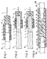
- la figure 1 est une vue en élévation et en coupe partielle montrant un équipement accessoire de raccordement selon l'invention monté sur un câble d'énergie,
- les figures 2 et 3 sont des vues analogues à la figure 1 pour des variantes de réalisation données par rapport à cette figure 1,
- la figure 4 est une vue en élévation et coupe partielle illustrant une jonction de câbles d'énergie et son équipement accessoire de raccordement selon l'invention.
- FIG. 1 is an elevational view in partial section showing an accessory connection equipment according to the invention mounted on an energy cable,
- FIGS. 2 and 3 are views similar to FIG. 1 for alternative embodiments given with respect to this FIG. 1,
- Figure 4 is an elevational view in partial section illustrating a junction of power cables and its accessory connection equipment according to the invention.
Dans les figures 1 à 4, les différentes parties constitutives de chaque câble d'énergie représenté sont identiques d'une figure à l'autre et sont désignées par les mêmes références numériques, ces références numériques étant simplement accompagnées de la lettre A ou B supplémentaire dans la figure 4. Le ou les câbles sont eux-mêmes désignés sous la référence globale 10, accompagnée de la lettre A pour l'un des câbles et de la lettre B pour l'autre, dans la figure 4.In FIGS. 1 to 4, the different constituent parts of each energy cable shown are identical from one figure to another and are designated by the same reference numbers, these reference numbers being simply accompanied by the additional letter A or B in FIG. 4. The cable (s) are themselves designated under the
On notera par ailleurs au préalable que toutes les conductivités électriques sont données à la température ambiante.It will also be noted beforehand that all the electrical conductivities are given at ambient temperature.
Chaque câble comporte une âme conductrice 1 et successivement un écran semi-conducteur interne 2, une couche diélectrique d'isolation 3, un écran semi-conducteur externe 4 et une gaine de protection extérieure 5. Cette gaine de protection est métallique et notamment en plomb ou en alliage de plomb, ou peut être isolante et est alors en général associée à un écran métallique directement sous-jacent, non représenté.Each cable comprises a conductive core 1 and successively an
Dans la figure 1, on voit que les parties constitutives du câble 10 ont été dénudées successivement en dégradé sur la partie terminale du câble et que cette partie terminale ainsi préparée porte un adaptateur 7 selon l'invention, dit également réducteur, entourant l'écran semi-conducteur externe dénudé 4 en partie, la couche diélectrique 3 dénudée et l'écran semi-conducteur interne 2 dénudé. Au-dessus de l'adaptateur 7 se trouve une couche semi-conductrice 11 servant à assurer la reconstitution de l'écran semi-conducteur externe 4 dénudé ainsi que la tenue diélectrique au niveau de ce dernier, et se prolongeant à cet effet jusqu'à lui en l'entourant en partie. L'ensemble comprenant l'adaptateur 7 et la couche semi-conductrice 11 constitue un équipement accessoire de raccordement 12 selon l'invention.In FIG. 1, it can be seen that the constituent parts of the
L'adaptateur 7 est réalisé, selon l'invention, en un matériau constitué par une matrice polymérique isolante contenant un polymère conducteur dédopé ou non dopé, incorporé avec un taux qui est au plus de 20% en masse dans la matrice.The adapter 7 is made, according to the invention, of a material constituted by an insulating polymer matrix containing a dedoped or undoped conductive polymer, incorporated with a rate which is at most 20% by mass in the matrix.
Selon une variante également avantageuse de l'invention, l'adaptateur 7 est réalisé en un matériau constitué par une matrice polymérique isolante contenant un polymère conducteur autodopé, incorporé avec un taux au plus égal à 5% en masse dans la matrice.According to an equally advantageous variant of the invention, the adapter 7 is made of a material consisting of an insulating polymer matrix containing a self-doping conductive polymer, incorporated with a content at most equal to 5% by mass in the matrix.
La couche semi-conductrice 11 a conductivité inférieure à 1 S/cm, aussi bien en courant continu qu'en courant alternatif, et peut être réalisée par exemple en un matériau du type de celui décrit dans le document EP-A-0 507 676, c'est-à-dire être constituée par une matrice polymérique isolante qui contient un polymère conducteur dédopé ou non dopé incorporé dans la matrice avec un taux de 5 à 70% en masse, de préférence de 20 à 30%, ou bien un polymère conducteur autodopé, incorporé dans la matrice avec un taux supérieur à 5%, et de préférence de 10 à 40%.The
La couche 11 peut également être réalisée en un matériau semi-conducteur usuel.The
L'adaptateur 7 forme un manchon recouvrant les parties dénudées de l'écran semi-conducteur externe 4 (en partie), de la couche diélectrique 3 et de l'écran semi-conducteur interne 2. Il est directement moulé sur ces seules parties à recouvrir, ou est prémoulé et positionné sur ces parties puis éventuellement alors solidarisé mécaniquement au bout, en particulier par chauffage de l'extrémité correspondante du manchon en place et/ou de celle de l'écran semi-conducteur externe 4. Il présente un alésage central 17 dont la longueur et la section étagée correspondent aux longueurs respectives et aux sections respectives des parties qu'il recouvre.The adapter 7 forms a sleeve covering the stripped parts of the external semiconductor screen 4 (in part), of the dielectric layer 3 and of the
En variante, l'adaptateur 7 peut être constitué à partir d'une bande extrudée, ayant la même composition que le manchon précité, qui est enroulée autour des parties à recouvrir et leur est solidarisée mécaniquement.Alternatively, the adapter 7 can be formed from an extruded strip, having the same composition as the aforementioned sleeve, which is wound around the parts to be covered and is mechanically secured to them.
Dans la figure 2, la partie terminale du câble 10 est préparée par une coupe droite de l'écran semi-conducteur interne 2, de la couche diélectrique 3 et de l'écran semiconducteur externe 4 autour de l'âme 1, la gaine extérieure de protection 5 étant en partie retirée pour dénuder une partie de l'écran semi-conducteur externe 4. La partie terminale ainsi préparée porte un adaptateur 8 selon l'invention, recouvert d'une couche semi-conductrice 13 identique à la couche 11, l'adaptateur 8 et la couche 13 formant un équipement accessoire de raccordement 14 selon l'invention.In Figure 2, the end part of the
L'adaptateur 8 est de même composition que l'adaptateur 7 de la figure 1. Il recouvre sur une courte longueur l'âme dénudée, ainsi que l'écran semi-conducteur externe 4 dénudé. Il constitue un manchon qui est directement moulé en place ou est prémoulé, positionné en place sur la partie terminale préparée du câble 10 et est rendu avantageusement adhérent sur la section droite de coupe pour un bon contact du manchon sur celle-ci.The adapter 8 is of the same composition as the adapter 7 of FIG. 1. It covers over a short length the stripped core, as well as the stripped external semiconductor screen 4. It constitutes a sleeve which is directly molded in place or is pre-molded, positioned in place on the prepared terminal part of the
L'alésage 18 de l'adaptateur 8 présente un épaulement unique à angle droit. Sa section de part et d'autre de cet épaulement correspond aux sections respectives de l'écran semi-conducteur externe 4 et de l'âme 1.The bore 18 of the adapter 8 has a single shoulder at a right angle. Its section on either side of this shoulder corresponds to the respective sections of the external semiconductor screen 4 and of the core 1.
La couche semi-conductrice 13 recouvre en partie l'adaptateur 8 et s'étend jusqu'à l'écran semi-conducteur externe 4 en le recouvrant en partie.The semiconductor layer 13 partially covers the adapter 8 and extends to the external semiconductor screen 4 by partially covering it.
Dans la figure 3, la partie terminale du câble 10 est préparée, non pas par une coupe droite comme dans la figure 2 mais par une coupe biaise continue de l'écran semiconducteur externe 4 et de la couche diélectrique 3 et une coupe droite, à la suite, de l'écran semi-conducteur interne 2, pour la mise à nu de l'âme 1. Elle porte un adaptateur 9 selon l'invention, analogue à l'adaptateur 8, dont l'alésage 19 présente des portions terminales opposées dont les sections respectives correspondent à celles de l'écran semiconducteur externe 4 et de l'âme 1, respectivement, mais un épaulement intermédiaire tronconique correspondant à la coupe biaise de dénudage de l'âme 1.In FIG. 3, the end part of the
Cette coupe biaise de dénudage permet un meilleur contact de l'adaptateur 9 ainsi qu'une meilleure adhésion sur la section tronconique de coupe.This stripping bias cut allows better contact of the adapter 9 as well as better adhesion to the frustoconical section of the cut.
L'adaptateur 9 est recouvert d'une couche semi-conductrice 15 identique à la couche semi-conductrice 13 et qui s'étend jusqu'à l'écran semi-conducteur externe 4 en le recouvrant en partie. L'adaptateur 9 et la couche 15 forment un équipement accessoire de raccordement 16 selon l'invention.The adapter 9 is covered with a
Dans la figure 4 illustrant une jonction de deux câbles 10A et 10B, les parties terminales des câbles à raccorder sont dénudées successivement en dégradé ou en variante peuvent être dénudées par une coupe biaise. Un élément connexion 20 raccorde les extrémités des âmes 1A et 1B dénudées. Un manchon ou adaptateur 21 selon l'invention, de même composition que les adaptateurs des figures 1 à 3, est moulé sur l'élément de connexion 20 et de part et d'autre sur les parties dénudées et les portions terminales des écrans semi-conducteurs 4A et 4B des deux câbles 10A et 10B. Il renforce la tenue mécanique du raccordement des âmes 1A et 1B, de sorte que l'élément de connexion 20 peut être constitué par une pièce de connexion de raccordement mécanique et électrique ou peut être constitué par une simple soudure de raccordement électrique mais de relativement faible tenue mécanique.In Figure 4 illustrating a junction of two
Le manchon 21 est recouvert d'une couche semi-conductrice 22 qui se prolonge sur les écrans semiconducteurs 4A et 4B et assure ainsi leur continuité.The
En variante, le manchon 21 surmoulé directement en place peut être remplacé par un rubanage de même composition mis en place sur les parties à recouvrir.Alternatively, the
Bien entendu, la jonction peut comporter en outre, de manière connue et non représentée, un dissipateur thermique, monté autour de la pièce de connexion et s'étendant de part et d'autre de cette dernière sur les âmes dénudées, ainsi que deux réducteurs, montés d'un côté et de l'autre du dissipateur sur les couches diélectriques 3A et 3B dénudées des deux câbles.Of course, the junction may further comprise, in a known manner and not shown, a heat sink, mounted around the connection piece and extending on either side of the latter on the stripped cores, as well as two reducers , mounted on one side and the other of the dissipator on the stripped
Avantageusement, le manchon 21 assure simultanément les fonctions d'un tel dissipateur thermique et des deux réducteurs dans cette jonction, ainsi rendus non nécessaires dans la jonction.Advantageously, the
On précise ci-après la composition de l'équipement accessoire de raccordement selon l'invention et sa fonction principale résultant de cette composition.The composition of the accessory connection equipment according to the invention and its main function resulting from this composition are specified below.
La matrice polymérique isolante et le polymère conducteur de cet équipement accessoire sont constitués par des polymères qui sont identiques à ceux utilisés dans la réalisation de l'écran semi-conducteur décrit dans le document EP-A-0 507 676.The insulating polymer matrix and the conductive polymer of this accessory equipment consist of polymers which are identical to those used in the production of the semiconductor screen described in document EP-A-0 507 676.
Ainsi, la matrice polymérique de l'équipement accessoire comprend au moins un polymère thermoplastique, choisi parmi les résines acryliques, styréniques vinyliques et cellulosiques, les polyoléfines, les polymères fluorés, les polyéthers, les polyimides, les polycarbonates, les polyuréthannes, les silicones leurs copolymères, et les mélanges entre homopolymères et entre homopolymères et copolymères.Thus, the polymer matrix of the accessory equipment comprises at least one thermoplastic polymer, chosen from acrylic resins, vinyl styrenics and cellulosics, polyolefins, fluorinated polymers, polyethers, polyimides, polycarbonates, polyurethanes, their silicones. copolymers, and mixtures between homopolymers and between homopolymers and copolymers.
En particulier, ce polymère thermoplastique est choisi parmi le polypropylène (PP), le polyéthylène (PE), le copolymère d'éthylène et d'acétate de vinyle (EVA), l'éthylène-proprylène-diène-monomère (EPDM), le polyvinylidène fluoré (PVDF), l'éthylène-butylacrylate (EBA), seuls ou en mélange.In particular, this thermoplastic polymer is chosen from polypropylene (PP), polyethylene (PE), the copolymer of ethylene and vinyl acetate (EVA), ethylene-proprylene-diene-monomer (EPDM), fluorinated polyvinylidene (PVDF), ethylene-butylacrylate (EBA), alone or as a mixture.
En variante, cette matrice polymérique comprend au moins un polymère thermodurcissable choisi parmi les polyesters, les résines époxydes et les résines phénoliques.As a variant, this polymer matrix comprises at least one thermosetting polymer chosen from polyesters, epoxy resins and phenolic resins.
Le ou les polymères conducteurs non dopés ou dopés et alors dédopés incorporés dans cette matrice polymérique sont choisis dans le groupe comprenant la polyaniline, le polythiophène, le polypyrrole, le polyacétylène, le polyparaphénylène, les polyalkyltiophènes, leurs dérivés et leurs mélanges.The undoped or doped and then dedoped conductive polymer (s) incorporated in this polymer matrix are chosen from the group comprising polyaniline, polythiophene, polypyrrole, polyacetylene, polyparaphenylene, polyalkyltiophenes, their derivatives and their mixtures.
Ces polymères non dopés et dédopés ne contiennent pas de groupements ioniques. Leur conductivité électrique intrinsèque, mesurée en courant continu, est très faible et de l'ordre de 10⁻¹⁰ à 10⁻⁹ S/cm. La conductivité de l'équipement accessoire, constitué par cette matrice polymérique contenant au plus 20% en masse de polymère non dopé ou dédopé, est de l'ordre de 10⁻¹⁴ S/cm aux bas champs électriques pour une utilisation en courant continu, et de 10⁻¹⁰ S/cm aux bas champs électriques pour une utilisation en courant alternatif. Elle peut être localement de l'ordre de 10⁻⁹ S/cm aux champs électriques élevés à répartir.These undoped and dedoped polymers do not contain ionic groups. Their intrinsic electrical conductivity, measured in direct current, is very low and of the order of 10⁻¹⁰ to 10⁻⁹ S / cm. The conductivity of the accessory equipment, constituted by this polymer matrix containing at most 20% by mass of undoped or dedoped polymer, is of the order of 10⁻¹⁴ S / cm at low electric fields for use in direct current, and 10⁻¹⁰ S / cm at low electric fields for use in alternating current. It can be locally of the order of 10⁻⁹ S / cm at the high electric fields to be distributed.
Lorsque l'on incorpore dans la matrice des polymères autodopés, ces derniers sont choisi dans le groupe comprenant les polyanilines autodopées présentant des noyaux benzéniques ou benzéniques et quinoniques, qui portent des greffons constitués pour les uns par un radical hydrocarboné, comportant de 2 à 8 atomes de carbone et interrompu par au moins un hétéro-atome, et pour les autres par une fonction acide fort ou un de ses sels, ledit hétéro-atome étant lui-même choisi parmi O et S et la fonction acide fort parmi les résidus d'acides sulfonique, phosphonique et phosphorique ou de leurs sels.When self-doped polymers are incorporated into the matrix, the latter are chosen from the group comprising autodoped polyanilines having benzene or benzene and quinone nuclei, which carry grafts consisting for the one of a hydrocarbon radical, comprising from 2 to 8 carbon atoms and interrupted by at least one hetero atom, and for the others by a strong acid function or one of its salts, said hetero atom being itself chosen from O and S and the strong acid function from the residues of sulfonic, phosphonic and phosphoric acids or their salts.
La conductivité électrique intrinsèque, mesurée en courant continu, de ces polymères autodopés est en moyenne de l'ordre de 10⁻³ à 10⁻² S/cm. Elle est en outre ajustable à souhait entre 10⁻⁵ et 1 S/cm, par variation du rapport moléculaire des deux types de greffons. La conductivité électrique de l'équipement accessoire, constitué par la matrice polymérique ci-avant à laquelle est ajouté au plus 5% en masse de ce polymère autodopé, est elle-même ajustable et de l'ordre ou inférieure à 10⁻¹⁴ S/cm pour une utilisation aux bas champs électriques en courant continu, et de l'ordre ou inférieure à 10⁻¹⁰ S/cm pour une utilisation en courant alternatif aux bas champs électriques.The intrinsic electrical conductivity, measured in direct current, of these self-doped polymers is on the order of 10⁻³ to 10⁻² S / cm on average. It is also adjustable as desired between 10⁻⁵ and 1 S / cm, by varying the molecular ratio of the two types of grafts. The electrical conductivity of the accessory equipment, consisting of the above polymer matrix to which is added at most 5% by mass of this self-doped polymer, is itself adjustable and of the order or less than 10⁻¹⁴ S / cm for use at low electric fields in direct current, and of the order or less than 10⁻¹⁰ S / cm for use in alternating current at low electric fields.
Un tel équipement accessoire de raccordement en cette composition est fondamentalement diélectrique, sauf localement le cas échéant lorsqu'il est soumis à un champ électrique élevé et devient alors substantiellement conducteur pour jouer le rôle de déflecteur intégré qui est de plus adapté au champ électrique existant ainsi réparti.Such accessory accessory equipment in this composition is basically dielectric, except locally if necessary when it is subjected to a high electric field and then becomes substantially conductive to play the role of integrated deflector which is moreover adapted to the existing electric field as well. distributed.
Parmi les autres avantages que procure l'équipement accessoire de raccordement selon la présente invention, on cite notamment :
- la simplicité et la rapidité possible de l'opération préliminaire de dénudage de la partie terminale du ou des câbles,
- la réalisation aisée et rapide du manchon ou du ruban et la possible mise en oeuvre directe de l'équipement accessoire par surmoulage de la partie terminale préparée du ou des câbles,
- la fiabilité accrue de l'équipement accessoire,
- les fonctions de dissipateur thermique et de réducteurs assurées simultanément dans une jonction, ainsi elle-même simplifiée.
- the simplicity and possible speed of the preliminary stripping operation of the terminal part of the cable (s),
- easy and quick production of the sleeve or ribbon and the possible direct implementation of the accessory equipment by overmolding of the prepared end part of the or cables,
- increased reliability of accessory equipment,
- the functions of heat sink and reducers performed simultaneously in a junction, thus simplified.
Bien évidemment, l'invention n'est pas limitée aux modes de réalisation qui viennent d'être décrits.Obviously, the invention is not limited to the embodiments which have just been described.
Notamment, l'équipement accessoire selon l'invention peut être réalisé par un procédé classique, avec éventuellement addition de charges minérales, de stabilisants, d'agents réticulants, etc... aux différents matériaux utilisés.In particular, the accessory equipment according to the invention can be produced by a conventional process, with the possible addition of mineral fillers, stabilizers, crosslinking agents, etc. to the various materials used.
Les couches semi-conductrices servant à assurer la reconstitution des écrans semi-conducteurs externes peuvent être constituées de tout matériau semi-conducteur usuel.The semiconductor layers used to ensure the reconstitution of the external semiconductor screens can be made of any usual semiconductor material.
Par ailleurs, au-dessus de l'équipement accessoire selon l'invention, on peut disposer, à la manière habituelle, une enveloppe de protection externe.Furthermore, above the accessory equipment according to the invention, there may be, in the usual manner, an external protective envelope.
Claims (6)
caractérisé en ce que lesdites première et deuxième parties dudit équipement accessoire de raccordement sont réalisées identiquement et simultanément en une matrice polymérique isolante contenant au moins un polymère conducteur, incorporé dans ladite matrice polymérique avec un taux massique tel que la conductivité électrique résultante desdites première et deuxième parties est inférieure à 10⁻¹⁴ S/cm pour une utilisation en courant continu, et inférieure à 10⁻¹⁰ S/cm pour une utilisation en courant alternatif, et en ce que ladite troisième partie a une conductivité électrique inférieure à 1 S/cm. 1) Accessory equipment for power cable connection, intended to be mounted on a stripped end portion of said cable and to ensure dielectric strength around said stripped end portion, said cable comprising a conductive core and successively around said core, an internal semiconductor screen, a dielectric layer, an external semiconductor screen and an external protective sheath and said accessory equipment comprising a first part intended to ensure the reconstitution of said dielectric layer, a second and a third associated parts intended for ensure the reconstruction of said internal semiconductor screen and said external semiconductor screen respectively,
characterized in that said first and second parts of said accessory connection equipment are produced identically and simultaneously in an insulating polymer matrix containing at least one conductive polymer, incorporated in said polymer matrix with a mass rate such that the electrical conductivity resulting from said first and second parts is less than 10⁻¹⁴ S / cm for use in direct current, and less than 10⁻¹⁰ S / cm for use in alternating current, and in that said third part has an electrical conductivity less than 1 S / cm .
Applications Claiming Priority (2)
| Application Number | Priority Date | Filing Date | Title |
|---|---|---|---|
| FR9311118A FR2710204B1 (en) | 1993-09-17 | 1993-09-17 | Accessory equipment for connecting an energy cable and energy cable thus equipped. |
| FR9311118 | 1993-09-17 |
Publications (3)
| Publication Number | Publication Date |
|---|---|
| EP0644641A2 true EP0644641A2 (en) | 1995-03-22 |
| EP0644641A3 EP0644641A3 (en) | 1997-09-17 |
| EP0644641B1 EP0644641B1 (en) | 1999-11-24 |
Family
ID=9450989
Family Applications (1)
| Application Number | Title | Priority Date | Filing Date |
|---|---|---|---|
| EP94402054A Expired - Lifetime EP0644641B1 (en) | 1993-09-17 | 1994-09-14 | Equipment for power cable junction and power cable equipped therewith |
Country Status (9)
| Country | Link |
|---|---|
| EP (1) | EP0644641B1 (en) |
| JP (1) | JPH07170624A (en) |
| KR (1) | KR950009754A (en) |
| CN (1) | CN1113045A (en) |
| AU (1) | AU683680B2 (en) |
| DE (1) | DE69421781T2 (en) |
| DK (1) | DK0644641T3 (en) |
| FR (1) | FR2710204B1 (en) |
| NO (1) | NO943427L (en) |
Cited By (1)
| Publication number | Priority date | Publication date | Assignee | Title |
|---|---|---|---|---|
| EP0886340A1 (en) * | 1997-06-16 | 1998-12-23 | Alcatel | Cable joint |
Families Citing this family (7)
| Publication number | Priority date | Publication date | Assignee | Title |
|---|---|---|---|---|
| EP2639264A1 (en) * | 2012-03-14 | 2013-09-18 | Nexans | Field grading material |
| CN103595010B (en) * | 2013-12-03 | 2016-09-07 | 深圳市沃尔核材股份有限公司 | A kind of insulated enclosure method of non-isometrical object |
| CN103595012B (en) * | 2013-12-03 | 2016-09-07 | 深圳市沃尔核材股份有限公司 | A kind of insulated enclosure method of non-isometrical object |
| BR112019005174B1 (en) * | 2016-09-19 | 2022-10-25 | Prysmian S.P.A | GASKET FOR HIGH VOLTAGE DC CURRENT CABLES |
| DE102018116399A1 (en) * | 2018-07-06 | 2020-01-09 | Nkt Gmbh & Co. Kg | coupling sleeve |
| EP3745425B1 (en) * | 2019-05-31 | 2022-12-21 | Aptiv Technologies Limited | Communications cables for autonomous vehicles |
| US11276971B2 (en) | 2019-05-31 | 2022-03-15 | Aptiv Technologies Limited | Hermaphroditic cable connectors for autonomous vehicles |
Citations (3)
| Publication number | Priority date | Publication date | Assignee | Title |
|---|---|---|---|---|
| GB2111769A (en) * | 1978-09-14 | 1983-07-06 | Raychem Ltd | Enclosure for cable termination or joint |
| US4822952A (en) * | 1985-08-21 | 1989-04-18 | Cable Technology Laboratories, Inc. | Electrical cable joint and electrical cable termination and methods of making same |
| EP0507676A2 (en) * | 1991-04-02 | 1992-10-07 | Alcatel Cable | Material for semiconductor screen |
-
1993
- 1993-09-17 FR FR9311118A patent/FR2710204B1/en not_active Expired - Fee Related
-
1994
- 1994-09-14 DE DE69421781T patent/DE69421781T2/en not_active Expired - Fee Related
- 1994-09-14 EP EP94402054A patent/EP0644641B1/en not_active Expired - Lifetime
- 1994-09-14 DK DK94402054T patent/DK0644641T3/en active
- 1994-09-14 AU AU72966/94A patent/AU683680B2/en not_active Ceased
- 1994-09-15 NO NO943427A patent/NO943427L/en not_active Application Discontinuation
- 1994-09-16 JP JP6222104A patent/JPH07170624A/en active Pending
- 1994-09-16 CN CN94115386A patent/CN1113045A/en active Pending
- 1994-09-16 KR KR1019940023608A patent/KR950009754A/en not_active Application Discontinuation
Patent Citations (3)
| Publication number | Priority date | Publication date | Assignee | Title |
|---|---|---|---|---|
| GB2111769A (en) * | 1978-09-14 | 1983-07-06 | Raychem Ltd | Enclosure for cable termination or joint |
| US4822952A (en) * | 1985-08-21 | 1989-04-18 | Cable Technology Laboratories, Inc. | Electrical cable joint and electrical cable termination and methods of making same |
| EP0507676A2 (en) * | 1991-04-02 | 1992-10-07 | Alcatel Cable | Material for semiconductor screen |
Cited By (2)
| Publication number | Priority date | Publication date | Assignee | Title |
|---|---|---|---|---|
| EP0886340A1 (en) * | 1997-06-16 | 1998-12-23 | Alcatel | Cable joint |
| US6105247A (en) * | 1997-06-16 | 2000-08-22 | Alcatel | Method of making a cable joint |
Also Published As
| Publication number | Publication date |
|---|---|
| FR2710204A1 (en) | 1995-03-24 |
| DK0644641T3 (en) | 2000-05-22 |
| FR2710204B1 (en) | 1995-10-20 |
| JPH07170624A (en) | 1995-07-04 |
| NO943427L (en) | 1995-03-20 |
| DE69421781D1 (en) | 1999-12-30 |
| NO943427D0 (en) | 1994-09-15 |
| CN1113045A (en) | 1995-12-06 |
| AU7296694A (en) | 1995-03-30 |
| EP0644641B1 (en) | 1999-11-24 |
| EP0644641A3 (en) | 1997-09-17 |
| KR950009754A (en) | 1995-04-24 |
| AU683680B2 (en) | 1997-11-20 |
| DE69421781T2 (en) | 2000-06-29 |
Similar Documents
| Publication | Publication Date | Title |
|---|---|---|
| EP0587492B1 (en) | Low-noise cable | |
| EP0129485B1 (en) | Electric-cable structure and its application | |
| EP2859633B1 (en) | Device with a charge sealing layer | |
| FR2738947A1 (en) | MULTIPAIR CABLE, SHIELD BY PAIR AND CONNECTING SOCKET | |
| CA2088215C (en) | High frequency electric cable | |
| EP2765581B1 (en) | Electric cable resistant to partial discharges | |
| FR2698736A1 (en) | Fabricating lightning conductor for use in high voltage electricity distribution network - using varistor disc stack with flexible sheath cover and outer extruded section with fins | |
| GB2132788A (en) | Fibre optic cable in electrical environment | |
| CA1217249A (en) | Electrical stress control apparatus and method | |
| EP2483894A1 (en) | Medium- or high-voltage electric cable | |
| FR2980622A1 (en) | ELECTRIC ELEMENT COMPRISING A LAYER OF A POLYMERIC MATERIAL WITH A GRADIENT OF ELECTRICAL CONDUCTIVITY | |
| EP0644641B1 (en) | Equipment for power cable junction and power cable equipped therewith | |
| EP0645781B1 (en) | Power cable with improved dielectric strength | |
| EP3422366A1 (en) | Cable comprising an electrically conductive element comprising metallised carbon fibres | |
| EP0552082A1 (en) | Protection for medium voltage cable termination | |
| EP0833421B1 (en) | Fitting for cable end and material constituting the fitting | |
| EP0115322B1 (en) | Moulded device covering a medium voltage electrical cable end | |
| FR2601184A1 (en) | Electrical safety (security) cable which is fire-resistant and does not propagate fire, and the process for manufacturing it | |
| EP0405538A1 (en) | Watertight polyphase electrical low-voltage energy cable | |
| FR2596568A1 (en) | Piezoelectric cable and process for manufacturing a cable | |
| FR2710184A1 (en) | Power cable with improved dielectric strength | |
| EP2498264B1 (en) | Medium- or high-voltage electrical cable | |
| FR3113978A1 (en) | Electric cable for the aeronautical field | |
| CA1266102A (en) | Electric cables | |
| FR3113979A1 (en) | Electric cable limiting partial discharges |
Legal Events
| Date | Code | Title | Description |
|---|---|---|---|
| PUAI | Public reference made under article 153(3) epc to a published international application that has entered the european phase |
Free format text: ORIGINAL CODE: 0009012 |
|
| AK | Designated contracting states |
Kind code of ref document: A2 Designated state(s): CH DE DK FR GB IT LI NL SE |
|
| PUAL | Search report despatched |
Free format text: ORIGINAL CODE: 0009013 |
|
| AK | Designated contracting states |
Kind code of ref document: A3 Designated state(s): CH DE DK FR GB IT LI NL SE |
|
| 17P | Request for examination filed |
Effective date: 19980219 |
|
| GRAG | Despatch of communication of intention to grant |
Free format text: ORIGINAL CODE: EPIDOS AGRA |
|
| 17Q | First examination report despatched |
Effective date: 19981130 |
|
| GRAG | Despatch of communication of intention to grant |
Free format text: ORIGINAL CODE: EPIDOS AGRA |
|
| GRAH | Despatch of communication of intention to grant a patent |
Free format text: ORIGINAL CODE: EPIDOS IGRA |
|
| GRAH | Despatch of communication of intention to grant a patent |
Free format text: ORIGINAL CODE: EPIDOS IGRA |
|
| RAP1 | Party data changed (applicant data changed or rights of an application transferred) |
Owner name: ALCATEL |
|
| GRAA | (expected) grant |
Free format text: ORIGINAL CODE: 0009210 |
|
| AK | Designated contracting states |
Kind code of ref document: B1 Designated state(s): CH DE DK FR GB IT LI NL SE |
|
| REG | Reference to a national code |
Ref country code: CH Ref legal event code: EP |
|
| REF | Corresponds to: |
Ref document number: 69421781 Country of ref document: DE Date of ref document: 19991230 |
|
| GBT | Gb: translation of ep patent filed (gb section 77(6)(a)/1977) |
Effective date: 19991224 |
|
| ITF | It: translation for a ep patent filed |
Owner name: JACOBACCI & PERANI S.P.A. |
|
| REG | Reference to a national code |
Ref country code: DK Ref legal event code: T3 |
|
| PGFP | Annual fee paid to national office [announced via postgrant information from national office to epo] |
Ref country code: GB Payment date: 20000814 Year of fee payment: 7 |
|
| PGFP | Annual fee paid to national office [announced via postgrant information from national office to epo] |
Ref country code: CH Payment date: 20000816 Year of fee payment: 7 |
|
| PGFP | Annual fee paid to national office [announced via postgrant information from national office to epo] |
Ref country code: NL Payment date: 20000824 Year of fee payment: 7 |
|
| PGFP | Annual fee paid to national office [announced via postgrant information from national office to epo] |
Ref country code: SE Payment date: 20000825 Year of fee payment: 7 Ref country code: DK Payment date: 20000825 Year of fee payment: 7 |
|
| PGFP | Annual fee paid to national office [announced via postgrant information from national office to epo] |
Ref country code: DE Payment date: 20000830 Year of fee payment: 7 |
|
| PGFP | Annual fee paid to national office [announced via postgrant information from national office to epo] |
Ref country code: FR Payment date: 20000831 Year of fee payment: 7 |
|
| PLBE | No opposition filed within time limit |
Free format text: ORIGINAL CODE: 0009261 |
|
| STAA | Information on the status of an ep patent application or granted ep patent |
Free format text: STATUS: NO OPPOSITION FILED WITHIN TIME LIMIT |
|
| 26N | No opposition filed | ||
| REG | Reference to a national code |
Ref country code: CH Ref legal event code: PUE Owner name: ALCATEL TRANSFER- NEXANS |
|
| NLS | Nl: assignments of ep-patents |
Owner name: NEXANS |
|
| PG25 | Lapsed in a contracting state [announced via postgrant information from national office to epo] |
Ref country code: GB Free format text: LAPSE BECAUSE OF NON-PAYMENT OF DUE FEES Effective date: 20010914 Ref country code: DK Free format text: LAPSE BECAUSE OF NON-PAYMENT OF DUE FEES Effective date: 20010914 |
|
| PG25 | Lapsed in a contracting state [announced via postgrant information from national office to epo] |
Ref country code: SE Free format text: LAPSE BECAUSE OF NON-PAYMENT OF DUE FEES Effective date: 20010915 |
|
| PG25 | Lapsed in a contracting state [announced via postgrant information from national office to epo] |
Ref country code: LI Free format text: LAPSE BECAUSE OF NON-PAYMENT OF DUE FEES Effective date: 20010930 Ref country code: CH Free format text: LAPSE BECAUSE OF NON-PAYMENT OF DUE FEES Effective date: 20010930 |
|
| REG | Reference to a national code |
Ref country code: GB Ref legal event code: IF02 |
|
| PG25 | Lapsed in a contracting state [announced via postgrant information from national office to epo] |
Ref country code: NL Free format text: LAPSE BECAUSE OF NON-PAYMENT OF DUE FEES Effective date: 20020401 |
|
| GBPC | Gb: european patent ceased through non-payment of renewal fee |
Effective date: 20010914 |
|
| PG25 | Lapsed in a contracting state [announced via postgrant information from national office to epo] |
Ref country code: DE Free format text: LAPSE BECAUSE OF NON-PAYMENT OF DUE FEES Effective date: 20020501 |
|
| EUG | Se: european patent has lapsed |
Ref document number: 94402054.4 |
|
| REG | Reference to a national code |
Ref country code: CH Ref legal event code: PL |
|
| NLV4 | Nl: lapsed or anulled due to non-payment of the annual fee |
Effective date: 20020401 |
|
| REG | Reference to a national code |
Ref country code: DK Ref legal event code: EBP |
|
| NLV4 | Nl: lapsed or anulled due to non-payment of the annual fee |
Effective date: 20020401 |
|
| PG25 | Lapsed in a contracting state [announced via postgrant information from national office to epo] |
Ref country code: FR Free format text: LAPSE BECAUSE OF NON-PAYMENT OF DUE FEES Effective date: 20030603 |
|
| REG | Reference to a national code |
Ref country code: FR Ref legal event code: ST |
|
| PG25 | Lapsed in a contracting state [announced via postgrant information from national office to epo] |
Ref country code: IT Free format text: LAPSE BECAUSE OF NON-PAYMENT OF DUE FEES;WARNING: LAPSES OF ITALIAN PATENTS WITH EFFECTIVE DATE BEFORE 2007 MAY HAVE OCCURRED AT ANY TIME BEFORE 2007. THE CORRECT EFFECTIVE DATE MAY BE DIFFERENT FROM THE ONE RECORDED. Effective date: 20050914 |
|
| PG25 | Lapsed in a contracting state [announced via postgrant information from national office to epo] |
Ref country code: FR Free format text: LAPSE BECAUSE OF NON-PAYMENT OF DUE FEES Effective date: 20010930 |