EP0644640A2 - Installation raceway - Google Patents
Installation raceway Download PDFInfo
- Publication number
- EP0644640A2 EP0644640A2 EP94112019A EP94112019A EP0644640A2 EP 0644640 A2 EP0644640 A2 EP 0644640A2 EP 94112019 A EP94112019 A EP 94112019A EP 94112019 A EP94112019 A EP 94112019A EP 0644640 A2 EP0644640 A2 EP 0644640A2
- Authority
- EP
- European Patent Office
- Prior art keywords
- duct
- installation
- installation duct
- partition
- base
- Prior art date
- Legal status (The legal status is an assumption and is not a legal conclusion. Google has not performed a legal analysis and makes no representation as to the accuracy of the status listed.)
- Granted
Links
Images

Classifications
-
- E—FIXED CONSTRUCTIONS
- E04—BUILDING
- E04F—FINISHING WORK ON BUILDINGS, e.g. STAIRS, FLOORS
- E04F17/00—Vertical ducts; Channels, e.g. for drainage
- E04F17/08—Vertical ducts; Channels, e.g. for drainage for receiving utility lines, e.g. cables, pipes
-
- H—ELECTRICITY
- H02—GENERATION; CONVERSION OR DISTRIBUTION OF ELECTRIC POWER
- H02G—INSTALLATION OF ELECTRIC CABLES OR LINES, OR OF COMBINED OPTICAL AND ELECTRIC CABLES OR LINES
- H02G3/00—Installations of electric cables or lines or protective tubing therefor in or on buildings, equivalent structures or vehicles
- H02G3/02—Details
- H02G3/04—Protective tubing or conduits, e.g. cable ladders or cable troughs
- H02G3/0406—Details thereof
-
- H—ELECTRICITY
- H02—GENERATION; CONVERSION OR DISTRIBUTION OF ELECTRIC POWER
- H02G—INSTALLATION OF ELECTRIC CABLES OR LINES, OR OF COMBINED OPTICAL AND ELECTRIC CABLES OR LINES
- H02G3/00—Installations of electric cables or lines or protective tubing therefor in or on buildings, equivalent structures or vehicles
- H02G3/02—Details
- H02G3/04—Protective tubing or conduits, e.g. cable ladders or cable troughs
- H02G3/0437—Channels
Definitions
- the innovation relates to an installation duct for laying electrical lines with a floor and two side walls connected in one piece with it, at least one partition arranged in the longitudinal direction of the duct, which can be locked at the bottom of the installation duct, and a sealing cover.
- a generic cable duct is known from DE-OS 21 09 613.
- one or more knife bars which run parallel to the side walls, protrude from the bottom of the lower part and only extend into the part of the lower part near the bottom.
- a partition made of plastic is attached to one or more or all of these male connectors.
- This partition wall has a lower, fork-shaped holding part and an adjoining wall area which extends into the vicinity of the cover of the cable duct.
- the male header has a thickening on both sides near the bottom, which corresponds to a sleeve-like extension in the fork-shaped holding part of the partition. With this sleeve-like extension, the thickening of the male connector on both sides is gripped and the partition is thus fixed to the bottom of the cable duct. The installation effort of such a system is considerable.
- the innovation has set itself the task of specifying a partition system for installation ducts, which can be fixed on the bottom of the cable duct without great assembly effort.
- the innovation it is proposed that, at a defined distance from one another, in the bottom of the installation duct toward the duct, internal surface elevations are embossed, into which elongated holes aligned with the duct axis are embedded, and that the partition wall is L-shaped with a shorter, to the bottom of the Installation channel directed L-leg, in which embossed fastening tabs are integrally formed, which are only integrally connected to the L-leg on one narrow side, which can be inserted into the elongated holes at the bottom of the installation channel and lock the partition by moving under the flat elevations.
- the partition wall system according to the invention merely requires the elongated holes arranged at appropriate intervals from one another in the flat elevations on the bottom of the installation duct and the fastening tabs formed at the same intervals on the outside of the shorter L-leg. These fastening tabs are inserted into the elongated holes and then the partition is only moved axially, so that the fastening tabs engage under the sub-areas of the flat elevations adjoining the elongated holes. The installation of the partition in the installation duct is now complete.
- the flat elevations on the bottom of the installation duct correspond at least to the wall thickness of the fastening tabs in their clear engagement height. This means that there are no difficulties with the assembly of the partition even if the installation duct is, for example, firmly mounted on a base.
- the mounting brackets always have so much freedom of movement in the area of the flat elevations that jamming before reaching the end seat of the partition is not possible.
- fastening tabs are stamped into the L-leg at least up to the wall thickness of the flat elevations.
- the partition wall system enables the partition wall to be fixed on the duct floor without any problems; the assembly effort consists only of inserting the fastening tabs into the elongated holes and then moving the fastening tabs below the assigned areas of the flat elevations.
- the partition with the fastening tabs is inserted into the elongated hole in the flat elevations at the bottom of the installation duct and, depending on the position of the partition, shifted to the right or left and thus snapped into place. It has been found to be sufficient here that four fastening lugs per 2 m length of the installation duct and thus four flat elevations with the corresponding elongated holes are let in at the bottom of the installation duct.
- two or more traces of the flat elevations can be arranged parallel to one another on the duct floor. This has the advantage that if the distance between the tracks is unequal, occupancy chambers of different sizes can be arranged inside the installation duct or - if several partition walls are used - several duct chambers can be arranged side by side in the interior of the duct.
- FIG. 1 shows the partition 1 with the long L-leg 11 and the short L-leg 12. From the short L-leg 12 are the fastening tabs 121, 122, 123, 124 formed by stamping.
- the cross section of the fastening tabs is explained as follows using the example of the fastening tab 121:
- the fastening tab 121 is connected in one piece to the shorter L-leg 12 by its narrow side 1211.
- the narrow side 1211 is cranked and forms a receiving space 2 with the grip area 1212 of the fastening tab 121, which corresponds at least to the wall thickness of the flat elevation 311 on the bottom 31 of the installation duct 3 (FIG. 2).
- the grip area 1212 merges into the outward-facing bevel 1213, which is used for reasons of easier insertion when reaching under the wall areas adjoining the elongated holes of the flat elevations 311.
- the partition 1 shows the partition 1 with its long L-leg 11 and the short L-leg 12 inside the installation duct 3.
- the partition 1 is snapped onto the bottom 31 of the installation duct 3 in the manner already described.
- the fastening tabs 121, 122, 123 and 124 were arranged in the flat elevations 311 on the bottom 31 of the installation duct in order to produce the latching connection above the elongated holes.
- the elongated holes in the flat elevations 311 have an axial extension which allows the fastening tabs to be inserted into the elongated holes from above without the partition wall having to be tilted. Thereafter, the fastening tabs are brought under the assigned areas of the flat elevations by moving the partition and the partition 1 is clamped in this way to the bottom 31 of the installation duct 3.
Abstract
Description
Die Neuerung betrifft einen Installationskanal zur Verlegung von elektrischen Leitungen mit einem Boden und zwei einstückig mit diesem verbundenen Seitenwänden, wenigstens einer in Kanallängsrichtung angeordneten Trennwand, die am Boden des Installationskanals arretierbar ist, sowie einem Verschlußdeckel.The innovation relates to an installation duct for laying electrical lines with a floor and two side walls connected in one piece with it, at least one partition arranged in the longitudinal direction of the duct, which can be locked at the bottom of the installation duct, and a sealing cover.
Aus der DE-OS 21 09 613 ist ein gattungsgemäßer Kabelkanal bekannt. Bei diesem Kabelkanal ragen vom Boden des Unterteils eine oder mehrere parallel zu den Seitenwänden verlaufende Messerleisten ab, die sich nur in den bodennahen Teil des Unterteils hinein erstrecken. Auf eine oder mehrere oder alle dieser Messerleisten ist eine Trennwand aus Kunststoff aufgesteckt. Diese Trennwand besitzt einen unteren, gabelförmigen Halteteil und einen daran anschließenden Wandbereich, der sich bis in die Nähe des Deckels des Kabelkanals erstreckt. Die Messerleiste besitzt bodennah beidseitig eine Verdickung, die einer muffenartigen Erweiterung im gabelförmigen Halteteil der Trennwand entspricht. Mit dieser muffenartigen Erweiterung wird die beidseitige Verdickung der Messerleiste rastend übergriffen und die Trennwand damit am Boden des Kabelkanals festgelegt. Der Montageaufwand eines solchen Systems ist beträchtlich.A generic cable duct is known from DE-OS 21 09 613. In this cable duct, one or more knife bars, which run parallel to the side walls, protrude from the bottom of the lower part and only extend into the part of the lower part near the bottom. A partition made of plastic is attached to one or more or all of these male connectors. This partition wall has a lower, fork-shaped holding part and an adjoining wall area which extends into the vicinity of the cover of the cable duct. The male header has a thickening on both sides near the bottom, which corresponds to a sleeve-like extension in the fork-shaped holding part of the partition. With this sleeve-like extension, the thickening of the male connector on both sides is gripped and the partition is thus fixed to the bottom of the cable duct. The installation effort of such a system is considerable.
Aus dem DE-U 72 03 150 ist ein weiterer Installationskanal mit einem kastenartigen Profil bekannt, dessen eine Längsseite zum Einbringen der zu verlegenden Leitungen offen ausgebildet ist und nachträglich durch einen Deckel verschlossen werden kann. Am Boden dieses Kabelkanals sind abschnittsweise Rückhalteglieder festlegbar, die in sich ständerartig ausgebildet sind. Die Basis dieser Rückhalteglieder bildet eine in 90°-Richtung zum Stamm verlaufende Fußleiste, welche mittels mechanischer Schraubelemente am Boden des Kabelkanals festgelegt werden kann. Hier ist der Montageaufwand noch größer als beim zuvor geschilderten Stand der Technik.Another installation duct with a box-like profile is known from DE-U 72 03 150, one longitudinal side of which is open for the introduction of the lines to be laid and can be subsequently closed by a cover. At the bottom of this cable duct, retention members can be fixed in sections, which are designed in a stand-like manner. The basis of these retaining elements is a skirting board running in 90 ° to the trunk, which can be fixed to the bottom of the cable duct using mechanical screw elements. Here, the assembly effort is even greater than in the previously described prior art.
Die Neuerung hat sich demgegenüber die Aufgabe gestellt, ein Trennwandsystem für Installationskanäle anzugeben, welches ohne großen Montageaufwand am Boden des Kabelkanals festlegbar ist. Neuerungsgemäß wird dazu vorgeschlagen, daß in definiertem Abstand voneinander in den Boden des Installationskanals zum Kanal inneren gerichtete flächige Erhöhungen eingeprägt sind, in welche an der Kanalachse ausgerichtete Langlöcher eingelassen sind, und daß die Trennwand L-förmig gestaltet ist mit einem kürzeren, zum Boden des Installationskanals gerichteten L-Schenkel, in welchem durchgeprägte, nur noch an einer Schmalseite mit dem L-Schenkel einstückig verbundene Befestigungslaschen eingeformt sind, welche in die Langlöcher am Boden des Installationskanals einsetzbar sind und durch Verschieben unter die flächigen Erhöhungen die Trennwand arretieren.In contrast, the innovation has set itself the task of specifying a partition system for installation ducts, which can be fixed on the bottom of the cable duct without great assembly effort. According to the innovation, it is proposed that, at a defined distance from one another, in the bottom of the installation duct toward the duct, internal surface elevations are embossed, into which elongated holes aligned with the duct axis are embedded, and that the partition wall is L-shaped with a shorter, to the bottom of the Installation channel directed L-leg, in which embossed fastening tabs are integrally formed, which are only integrally connected to the L-leg on one narrow side, which can be inserted into the elongated holes at the bottom of the installation channel and lock the partition by moving under the flat elevations.
Das neuerungsgemäße Trennwandsystem benötigt lediglich die in entsprechenden Abständen voneinander angeordneten Langlöcher in den flächigen Erhöhungen am Boden des Installationskanals und die in den gleichen Abständen an der Außenseite des kürzeren L-Schenkels ausgeformten Befestigungslaschen. Diese Befestigungslaschen werden in die Langlöcher eingesetzt und danach wird die Trennwand lediglich axial verschoben, so daß die Befestigungslaschen die an die Langlöcher anschließenden Teilbereiche der flächigen Erhöhungen halternd untergreifen. Der Montagevorgang der Trennwand im Installationskanal ist damit abgeschlossen.The partition wall system according to the invention merely requires the elongated holes arranged at appropriate intervals from one another in the flat elevations on the bottom of the installation duct and the fastening tabs formed at the same intervals on the outside of the shorter L-leg. These fastening tabs are inserted into the elongated holes and then the partition is only moved axially, so that the fastening tabs engage under the sub-areas of the flat elevations adjoining the elongated holes. The installation of the partition in the installation duct is now complete.
Wichtig für den ungestörten Montagevorgang ist, daß die flächigen Erhöhungen am Boden des Installationskanals in ihrer lichten Hintergreifungshöhe wenigstens der Wanddicke der Befestigungslaschen entsprechen. Dadurch ergeben sich bei der Montage der Trennwand auch dann keine Schwierigkeiten, wenn der Installationskanal beispielsweise fest auf einer Unterlage montiert ist. Die Befestigungslaschen haben immer so viel Bewegungsspielraum im Bereich der flächigen Erhöhungen, daß ein Verklemmen vor dem Erreichen des Endsitzes der Trennwand nicht möglich ist.It is important for the undisturbed assembly process that the flat elevations on the bottom of the installation duct correspond at least to the wall thickness of the fastening tabs in their clear engagement height. This means that there are no difficulties with the assembly of the partition even if the installation duct is, for example, firmly mounted on a base. The mounting brackets always have so much freedom of movement in the area of the flat elevations that jamming before reaching the end seat of the partition is not possible.
Für die ungehinderte Montage der Trennwand am Kanalboden ist es ferner zweckmäßig, daß die Befestigungslaschen wenigstens bis zur Wanddicke der flächigen Erhöhungen in den L-Schenkel durchgeprägt sind.For the unimpeded assembly of the partition on the channel floor, it is also expedient that the fastening tabs are stamped into the L-leg at least up to the wall thickness of the flat elevations.
Das neuerungsgemäße Trennwandsystem ermöglicht ein unproblematisches Festlegen der Trennwand am Kanalboden; wobei der Montageaufwand nur noch aus dem Einsetzen der Befestigungslaschen in die Langlöcher und das anschließende Verschieben der Befestigungslaschen unter die zugeordneten Bereiche der flächigen Erhöhungen besteht. Hierbei wird die Trennwand mit den Befestigungslaschen in das Langloch der flächigen Erhöhungen am Boden des Installationskanals eingeführt und je nach Trennwandlage nach rechts oder links verschoben und somit eingerastet. Hierbei hat es sich als ausreichend erwiesen, daß vier Befestigungslaschen pro 2 m Länge des Installationskanals und damit vier flächige Erhöhungen mit den entsprechenden Langlöchern am Boden des Installationskanals eingelassen sind.The partition wall system according to the innovation enables the partition wall to be fixed on the duct floor without any problems; the assembly effort consists only of inserting the fastening tabs into the elongated holes and then moving the fastening tabs below the assigned areas of the flat elevations. Here, the partition with the fastening tabs is inserted into the elongated hole in the flat elevations at the bottom of the installation duct and, depending on the position of the partition, shifted to the right or left and thus snapped into place. It has been found to be sufficient here that four fastening lugs per 2 m length of the installation duct and thus four flat elevations with the corresponding elongated holes are let in at the bottom of the installation duct.
Bei breiteren Installationskanälen können zwei oder mehrere Spuren der flächigen Erhöhungen parallel zueinander am Kanalboden angeordnet sein. Das hat den Vorteil, daß bei ungleichem Abstand der Spuren verschieden große Belegungskammern innerhalb des Installationskanals oder - bei Verwendung mehrerer Trennwände - mehrere Kanalkammern nebeneinander im Kanalinneren angeordnet werden können.In the case of wider installation ducts, two or more traces of the flat elevations can be arranged parallel to one another on the duct floor. This has the advantage that if the distance between the tracks is unequal, occupancy chambers of different sizes can be arranged inside the installation duct or - if several partition walls are used - several duct chambers can be arranged side by side in the interior of the duct.
In der Zeichnung ist ein Ausführungsbeispiel des neuerungsgemäßen Installationskanals schematisch dargestellt; es zeigt:
- Fig.1 die Trennwand in Seitenansicht,
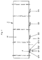
- Fig.2 die Trennwand in aufgerastetem Zustand im Inneren des Installationskanals im Schnitt.
- 1 the side wall,
- Fig.2 the partition in the locked state inside the installation duct in section.
Fig.1 zeigt die Trennwand 1 mit dem langen L-Schenkel 11 und dem kurzen L-Schenkel 12. Aus dem kurzen L-Schenkel 12 sind die Befestigungslaschen 121, 122, 123, 124 mittels Durchprägen ausgeformt. Der Querschnitt der Befestigungslaschen wird am Beispiel der Befestigungslasche 121 wie folgt erläutert:1 shows the
Die Befestigungslasche 121 ist mit ihrer Schmalseite 1211 einstückig mit dem kürzeren L-Schenkel 12 verbunden. Die Schmalseite 1211 ist abgekröpft und bildet mit dem Untergreifungsbereich 1212 der Befestigungslasche 121 einen Aufnahmeraum 2, der wenigstens der Wanddicke der flächigen Erhöhung 311 am Boden 31 des Installationskanals 3 (Fig.2) entspricht. Der Untergreifungsbereich 1212 geht an seinem freien Ende in die nach außen gerichtete Abschrägung 1213 über, die aus Gründen der leichteren Einführbarkeit beim Untergreifen der an die Langlöcher der flächigen Erhöhungen 311 anschließenden Wandbereiche dient.The
Fig.2 zeigt die Trennwand 1 mit ihrem langen L-Schenkel 11 und dem kurzen L-Schenkel 12 im inneren des Installationskanals 3. Die Trennwand 1 ist dabei in der bereits beschriebenen Weise auf dem Boden 31 des Installationskanals 3 aufgerastet. Die Befestigungslaschen 121, 122, 123 und 124 wurden zur Herstellung der Rastverbindung über den Langlöchern in den flächigen Erhöhungen 311 am Boden 31 des Installationskanals angeordnet. Die Langlöcher in den flächigen Erhöhungen 311 besitzen eine axiale Ausdehnung, die es erlaubt, die Befestigungslaschen ohne Kippen der Trennwand von oben in die Langlöcher einzusetzen. Danach werden die Befestigungslaschen durch Verschieben der Trennwand unter die zugeordneten Bereiche der flächigen Erhöhungen gebracht und die Trennwand 1 wird auf diese Weise klemmend am Boden 31 des Installationskanals 3 festgelegt.2 shows the
Claims (3)
Applications Claiming Priority (2)
| Application Number | Priority Date | Filing Date | Title |
|---|---|---|---|
| DE9313607U DE9313607U1 (en) | 1993-09-09 | 1993-09-09 | Installation duct |
| DE9313607U | 1993-09-09 |
Publications (3)
| Publication Number | Publication Date |
|---|---|
| EP0644640A2 true EP0644640A2 (en) | 1995-03-22 |
| EP0644640A3 EP0644640A3 (en) | 1996-01-03 |
| EP0644640B1 EP0644640B1 (en) | 1997-02-05 |
Family
ID=6897883
Family Applications (1)
| Application Number | Title | Priority Date | Filing Date |
|---|---|---|---|
| EP94112019A Expired - Lifetime EP0644640B1 (en) | 1993-09-09 | 1994-08-02 | Installation raceway |
Country Status (10)
| Country | Link |
|---|---|
| EP (1) | EP0644640B1 (en) |
| AT (1) | ATE148809T1 (en) |
| CZ (1) | CZ284569B6 (en) |
| DE (2) | DE9313607U1 (en) |
| DK (1) | DK0644640T3 (en) |
| ES (1) | ES2098083T3 (en) |
| GR (1) | GR3023139T3 (en) |
| HU (1) | HU214401B (en) |
| PL (1) | PL174949B1 (en) |
| SK (1) | SK106894A3 (en) |
Cited By (3)
| Publication number | Priority date | Publication date | Assignee | Title |
|---|---|---|---|---|
| EP0742625A1 (en) * | 1995-05-09 | 1996-11-13 | Hermann Kleinhuis GmbH. & Co. KG | Cable channel |
| CN101443973B (en) * | 2006-05-12 | 2012-01-04 | I.C.M.集团 | Separation and/or reinforcement device for a wire cable duct |
| US8183471B2 (en) | 2008-08-12 | 2012-05-22 | Mono-Systems, Inc. | Cable raceway |
Families Citing this family (1)
| Publication number | Priority date | Publication date | Assignee | Title |
|---|---|---|---|---|
| CN105337227B (en) * | 2015-10-30 | 2017-06-30 | 国网山东省电力公司东营供电公司 | Copper bar insulating boot in a kind of power transmission busbar |
Citations (4)
| Publication number | Priority date | Publication date | Assignee | Title |
|---|---|---|---|---|
| DE7203150U (en) * | 1972-05-10 | Fa H Kleinhuis | Installation channel | |
| DE2244596A1 (en) * | 1972-09-12 | 1974-03-21 | Ackermann A Fa | CABLE CHANNEL FOR POWERFUL AND / OR LOW CURRENT INSTALLATIONS |
| DE2911100A1 (en) * | 1979-03-21 | 1980-09-25 | Bettermann Ohg Neuwalzwerk | Two=part cable support racking - has L=shaped side supports to carry cable support deck with pins locking both together |
| GB2132421A (en) * | 1982-12-16 | 1984-07-04 | Ega Ltd | Cable trunking |
Family Cites Families (4)
| Publication number | Priority date | Publication date | Assignee | Title |
|---|---|---|---|---|
| DE2109613B2 (en) * | 1971-03-01 | 1973-02-08 | CABLE CHANNEL WITH PARTITION WALLS | |
| CH535882A (en) * | 1971-12-09 | 1973-04-15 | Gardy Particip App | Channel comprising a trough-shaped profile and a cover |
| DE2621375A1 (en) * | 1976-05-14 | 1977-11-24 | Bbc Brown Boveri & Cie | Installation duct of insulating plastic - has dimensions adapted to those of switches, socket outlets etc., with attachment for fastening partition |
| DE3426064C1 (en) * | 1984-07-14 | 1986-01-16 | OBO Bettermann oHG, 5750 Menden | Separating wall for a cable duct |
-
1993
- 1993-09-09 DE DE9313607U patent/DE9313607U1/en not_active Expired - Lifetime
-
1994
- 1994-08-02 AT AT94112019T patent/ATE148809T1/en not_active IP Right Cessation
- 1994-08-02 EP EP94112019A patent/EP0644640B1/en not_active Expired - Lifetime
- 1994-08-02 DK DK94112019.8T patent/DK0644640T3/en active
- 1994-08-02 DE DE59401755T patent/DE59401755D1/en not_active Expired - Fee Related
- 1994-08-02 ES ES94112019T patent/ES2098083T3/en not_active Expired - Lifetime
- 1994-08-30 CZ CZ942092A patent/CZ284569B6/en not_active IP Right Cessation
- 1994-08-31 HU HU9402512A patent/HU214401B/en not_active IP Right Cessation
- 1994-09-06 PL PL94304945A patent/PL174949B1/en unknown
- 1994-09-06 SK SK1068-94A patent/SK106894A3/en unknown
-
1997
- 1997-04-15 GR GR970400801T patent/GR3023139T3/en unknown
Patent Citations (4)
| Publication number | Priority date | Publication date | Assignee | Title |
|---|---|---|---|---|
| DE7203150U (en) * | 1972-05-10 | Fa H Kleinhuis | Installation channel | |
| DE2244596A1 (en) * | 1972-09-12 | 1974-03-21 | Ackermann A Fa | CABLE CHANNEL FOR POWERFUL AND / OR LOW CURRENT INSTALLATIONS |
| DE2911100A1 (en) * | 1979-03-21 | 1980-09-25 | Bettermann Ohg Neuwalzwerk | Two=part cable support racking - has L=shaped side supports to carry cable support deck with pins locking both together |
| GB2132421A (en) * | 1982-12-16 | 1984-07-04 | Ega Ltd | Cable trunking |
Cited By (3)
| Publication number | Priority date | Publication date | Assignee | Title |
|---|---|---|---|---|
| EP0742625A1 (en) * | 1995-05-09 | 1996-11-13 | Hermann Kleinhuis GmbH. & Co. KG | Cable channel |
| CN101443973B (en) * | 2006-05-12 | 2012-01-04 | I.C.M.集团 | Separation and/or reinforcement device for a wire cable duct |
| US8183471B2 (en) | 2008-08-12 | 2012-05-22 | Mono-Systems, Inc. | Cable raceway |
Also Published As
| Publication number | Publication date |
|---|---|
| ATE148809T1 (en) | 1997-02-15 |
| CZ284569B6 (en) | 1999-01-13 |
| EP0644640A3 (en) | 1996-01-03 |
| GR3023139T3 (en) | 1997-07-30 |
| HU9402512D0 (en) | 1994-10-28 |
| DE59401755D1 (en) | 1997-03-20 |
| PL304945A1 (en) | 1995-03-20 |
| DE9313607U1 (en) | 1993-11-18 |
| CZ209294A3 (en) | 1995-03-15 |
| DK0644640T3 (en) | 1997-07-28 |
| ES2098083T3 (en) | 1997-04-16 |
| EP0644640B1 (en) | 1997-02-05 |
| HU214401B (en) | 1998-03-30 |
| HUT68132A (en) | 1995-05-29 |
| PL174949B1 (en) | 1998-10-30 |
| SK106894A3 (en) | 1995-04-12 |
Similar Documents
| Publication | Publication Date | Title |
|---|---|---|
| EP0710405B1 (en) | Electrical connector, especially for motor vehicles | |
| EP3653925B1 (en) | Sealed lamp | |
| DE3340664A1 (en) | SEALING BELLOW OR SLEEVE FOR ARRANGEMENT IN BODY OPENINGS FOR THE PROTECTED PERFORMANCE OF CABLES AND THE LIKE | |
| EP0311769A2 (en) | Miniaturized spring contact plug | |
| DE102018200943A1 (en) | Retaining clip for mounting vehicle parts in a vehicle | |
| DE19728708C2 (en) | Arrangement for installing a wiring harness in an automobile door | |
| EP0702441B1 (en) | Electrical installation apparatus, especially for cable ducts | |
| EP1873882B1 (en) | Mounting device for a conduit | |
| DE19528252B4 (en) | Aggregate for a vehicle brake system | |
| EP0644640B1 (en) | Installation raceway | |
| DE19534205C2 (en) | Electrical connector | |
| DE102014205744A1 (en) | Control unit for a vehicle heater | |
| DE202010010424U1 (en) | Wall feed-through terminal for electrical conductors | |
| DE2515842A1 (en) | SCREWLESS TERMINAL OR CONNECTING CLAMP FOR ELECTRICAL CABLES | |
| DE102018123324B4 (en) | Safety device for mechanically securing at least one connector plug on a housing | |
| DE102016124609A1 (en) | Distribution box for installation in a wall opening | |
| EP1035989A1 (en) | Device for receiving and locating a battery | |
| DE60027072T2 (en) | Electrical plug connection, in particular for motor vehicle applications | |
| EP1622239B1 (en) | Actuator, in particular for vehicles, with an electrical component with a cable | |
| DE2804419A1 (en) | cable runway also supporting electrical fittings - has locking grooves along upper edges of side walls to hold cable bridges in position | |
| DE10393723B4 (en) | Plug connection and assembly method for producing at least one connection through an opening in a partition wall | |
| DE19640016A1 (en) | Structure for preventing a movable connector from rotating | |
| EP0742607A2 (en) | Contact spring | |
| DE19712809A1 (en) | Sealed electrical connector with lifting screw | |
| EP3675300B1 (en) | Adapter for positioning and fixing an installation housing |
Legal Events
| Date | Code | Title | Description |
|---|---|---|---|
| PUAI | Public reference made under article 153(3) epc to a published international application that has entered the european phase |
Free format text: ORIGINAL CODE: 0009012 |
|
| AK | Designated contracting states |
Kind code of ref document: A2 Designated state(s): AT BE CH DE DK ES FR GB GR IE IT LI LU NL PT SE |
|
| PUAL | Search report despatched |
Free format text: ORIGINAL CODE: 0009013 |
|
| AK | Designated contracting states |
Kind code of ref document: A3 Designated state(s): AT BE CH DE DK ES FR GB GR IE IT LI LU NL PT SE |
|
| 17P | Request for examination filed |
Effective date: 19960126 |
|
| GRAG | Despatch of communication of intention to grant |
Free format text: ORIGINAL CODE: EPIDOS AGRA |
|
| GRAH | Despatch of communication of intention to grant a patent |
Free format text: ORIGINAL CODE: EPIDOS IGRA |
|
| GRAH | Despatch of communication of intention to grant a patent |
Free format text: ORIGINAL CODE: EPIDOS IGRA |
|
| 17Q | First examination report despatched |
Effective date: 19960719 |
|
| GRAA | (expected) grant |
Free format text: ORIGINAL CODE: 0009210 |
|
| AK | Designated contracting states |
Kind code of ref document: B1 Designated state(s): AT BE CH DE DK ES FR GB GR IE IT LI LU NL PT SE |
|
| REF | Corresponds to: |
Ref document number: 148809 Country of ref document: AT Date of ref document: 19970215 Kind code of ref document: T |
|
| REG | Reference to a national code |
Ref country code: CH Ref legal event code: EP |
|
| REG | Reference to a national code |
Ref country code: IE Ref legal event code: FG4D Free format text: 71987 |
|
| ITF | It: translation for a ep patent filed |
Owner name: 0403;08MIFDE DOMINICIS & MAYER S.R.L. |
|
| REF | Corresponds to: |
Ref document number: 59401755 Country of ref document: DE Date of ref document: 19970320 |
|
| REG | Reference to a national code |
Ref country code: ES Ref legal event code: FG2A Ref document number: 2098083 Country of ref document: ES Kind code of ref document: T3 |
|
| GBT | Gb: translation of ep patent filed (gb section 77(6)(a)/1977) |
Effective date: 19970407 |
|
| ET | Fr: translation filed | ||
| REG | Reference to a national code |
Ref country code: GR Ref legal event code: FG4A Free format text: 3023139 |
|
| REG | Reference to a national code |
Ref country code: DK Ref legal event code: T3 |
|
| REG | Reference to a national code |
Ref country code: PT Ref legal event code: SC4A Free format text: AVAILABILITY OF NATIONAL TRANSLATION Effective date: 19970417 |
|
| PLBE | No opposition filed within time limit |
Free format text: ORIGINAL CODE: 0009261 |
|
| STAA | Information on the status of an ep patent application or granted ep patent |
Free format text: STATUS: NO OPPOSITION FILED WITHIN TIME LIMIT |
|
| 26N | No opposition filed | ||
| PGFP | Annual fee paid to national office [announced via postgrant information from national office to epo] |
Ref country code: GR Payment date: 20000712 Year of fee payment: 7 |
|
| PGFP | Annual fee paid to national office [announced via postgrant information from national office to epo] |
Ref country code: BE Payment date: 20000713 Year of fee payment: 7 |
|
| PGFP | Annual fee paid to national office [announced via postgrant information from national office to epo] |
Ref country code: PT Payment date: 20000714 Year of fee payment: 7 |
|
| PGFP | Annual fee paid to national office [announced via postgrant information from national office to epo] |
Ref country code: FR Payment date: 20000717 Year of fee payment: 7 |
|
| PGFP | Annual fee paid to national office [announced via postgrant information from national office to epo] |
Ref country code: AT Payment date: 20000718 Year of fee payment: 7 |
|
| PGFP | Annual fee paid to national office [announced via postgrant information from national office to epo] |
Ref country code: SE Payment date: 20000719 Year of fee payment: 7 Ref country code: CH Payment date: 20000719 Year of fee payment: 7 |
|
| PGFP | Annual fee paid to national office [announced via postgrant information from national office to epo] |
Ref country code: LU Payment date: 20000720 Year of fee payment: 7 |
|
| PGFP | Annual fee paid to national office [announced via postgrant information from national office to epo] |
Ref country code: IE Payment date: 20000721 Year of fee payment: 7 Ref country code: GB Payment date: 20000721 Year of fee payment: 7 |
|
| PGFP | Annual fee paid to national office [announced via postgrant information from national office to epo] |
Ref country code: DK Payment date: 20000724 Year of fee payment: 7 |
|
| PGFP | Annual fee paid to national office [announced via postgrant information from national office to epo] |
Ref country code: ES Payment date: 20000816 Year of fee payment: 7 |
|
| PGFP | Annual fee paid to national office [announced via postgrant information from national office to epo] |
Ref country code: NL Payment date: 20000831 Year of fee payment: 7 |
|
| PGFP | Annual fee paid to national office [announced via postgrant information from national office to epo] |
Ref country code: DE Payment date: 20010712 Year of fee payment: 8 |
|
| PG25 | Lapsed in a contracting state [announced via postgrant information from national office to epo] |
Ref country code: LU Free format text: LAPSE BECAUSE OF NON-PAYMENT OF DUE FEES Effective date: 20010802 Ref country code: IE Free format text: LAPSE BECAUSE OF NON-PAYMENT OF DUE FEES Effective date: 20010802 Ref country code: GB Free format text: LAPSE BECAUSE OF NON-PAYMENT OF DUE FEES Effective date: 20010802 Ref country code: DK Free format text: LAPSE BECAUSE OF NON-PAYMENT OF DUE FEES Effective date: 20010802 Ref country code: AT Free format text: LAPSE BECAUSE OF NON-PAYMENT OF DUE FEES Effective date: 20010802 |
|
| PG25 | Lapsed in a contracting state [announced via postgrant information from national office to epo] |
Ref country code: SE Free format text: LAPSE BECAUSE OF NON-PAYMENT OF DUE FEES Effective date: 20010803 Ref country code: ES Free format text: LAPSE BECAUSE OF NON-PAYMENT OF DUE FEES Effective date: 20010803 |
|
| PG25 | Lapsed in a contracting state [announced via postgrant information from national office to epo] |
Ref country code: LI Free format text: LAPSE BECAUSE OF NON-PAYMENT OF DUE FEES Effective date: 20010831 Ref country code: CH Free format text: LAPSE BECAUSE OF NON-PAYMENT OF DUE FEES Effective date: 20010831 Ref country code: BE Free format text: LAPSE BECAUSE OF NON-PAYMENT OF DUE FEES Effective date: 20010831 |
|
| PG25 | Lapsed in a contracting state [announced via postgrant information from national office to epo] |
Ref country code: GR Free format text: LAPSE BECAUSE OF NON-PAYMENT OF DUE FEES Effective date: 20020209 |
|
| BERE | Be: lapsed |
Owner name: REHAU A.G. + CO. Effective date: 20010831 |
|
| PG25 | Lapsed in a contracting state [announced via postgrant information from national office to epo] |
Ref country code: PT Free format text: LAPSE BECAUSE OF NON-PAYMENT OF DUE FEES Effective date: 20020228 |
|
| PG25 | Lapsed in a contracting state [announced via postgrant information from national office to epo] |
Ref country code: NL Free format text: LAPSE BECAUSE OF NON-PAYMENT OF DUE FEES Effective date: 20020301 |
|
| GBPC | Gb: european patent ceased through non-payment of renewal fee |
Effective date: 20010802 |
|
| EUG | Se: european patent has lapsed |
Ref document number: 94112019.8 |
|
| REG | Reference to a national code |
Ref country code: CH Ref legal event code: PL |
|
| REG | Reference to a national code |
Ref country code: DK Ref legal event code: EBP |
|
| PG25 | Lapsed in a contracting state [announced via postgrant information from national office to epo] |
Ref country code: FR Free format text: LAPSE BECAUSE OF NON-PAYMENT OF DUE FEES Effective date: 20020430 |
|
| NLV4 | Nl: lapsed or anulled due to non-payment of the annual fee |
Effective date: 20020301 |
|
| REG | Reference to a national code |
Ref country code: IE Ref legal event code: MM4A |
|
| REG | Reference to a national code |
Ref country code: FR Ref legal event code: ST |
|
| REG | Reference to a national code |
Ref country code: PT Ref legal event code: MM4A Free format text: LAPSE DUE TO NON-PAYMENT OF FEES Effective date: 20020228 |
|
| PG25 | Lapsed in a contracting state [announced via postgrant information from national office to epo] |
Ref country code: DE Free format text: LAPSE BECAUSE OF NON-PAYMENT OF DUE FEES Effective date: 20030301 |
|
| REG | Reference to a national code |
Ref country code: ES Ref legal event code: FD2A Effective date: 20020911 |
|
| PG25 | Lapsed in a contracting state [announced via postgrant information from national office to epo] |
Ref country code: IT Free format text: LAPSE BECAUSE OF NON-PAYMENT OF DUE FEES;WARNING: LAPSES OF ITALIAN PATENTS WITH EFFECTIVE DATE BEFORE 2007 MAY HAVE OCCURRED AT ANY TIME BEFORE 2007. THE CORRECT EFFECTIVE DATE MAY BE DIFFERENT FROM THE ONE RECORDED. Effective date: 20050802 |