EP0742625A1 - Cable channel - Google Patents
Cable channel Download PDFInfo
- Publication number
- EP0742625A1 EP0742625A1 EP95106954A EP95106954A EP0742625A1 EP 0742625 A1 EP0742625 A1 EP 0742625A1 EP 95106954 A EP95106954 A EP 95106954A EP 95106954 A EP95106954 A EP 95106954A EP 0742625 A1 EP0742625 A1 EP 0742625A1
- Authority
- EP
- European Patent Office
- Prior art keywords
- cable duct
- holding
- clip
- retaining clip
- duct according
- Prior art date
- Legal status (The legal status is an assumption and is not a legal conclusion. Google has not performed a legal analysis and makes no representation as to the accuracy of the status listed.)
- Granted
Links
Images


Classifications
-
- H—ELECTRICITY
- H02—GENERATION; CONVERSION OR DISTRIBUTION OF ELECTRIC POWER
- H02G—INSTALLATION OF ELECTRIC CABLES OR LINES, OR OF COMBINED OPTICAL AND ELECTRIC CABLES OR LINES
- H02G3/00—Installations of electric cables or lines or protective tubing therefor in or on buildings, equivalent structures or vehicles
- H02G3/02—Details
- H02G3/04—Protective tubing or conduits, e.g. cable ladders or cable troughs
- H02G3/0406—Details thereof
-
- H—ELECTRICITY
- H02—GENERATION; CONVERSION OR DISTRIBUTION OF ELECTRIC POWER
- H02G—INSTALLATION OF ELECTRIC CABLES OR LINES, OR OF COMBINED OPTICAL AND ELECTRIC CABLES OR LINES
- H02G3/00—Installations of electric cables or lines or protective tubing therefor in or on buildings, equivalent structures or vehicles
- H02G3/02—Details
- H02G3/04—Protective tubing or conduits, e.g. cable ladders or cable troughs
- H02G3/0437—Channels
Abstract
Description
Die Erfindung bezieht sich auf einen Kabelkanal, bestehend aus einem Kabelkanalunterteil und einem lösbar damit verbindbaren Deckel, bei dem die Seitenwandungen des Kabelkanalunterteils über Halteklammern abstandhaltend miteinander verbunden sind, und der Boden des Kabelkanalunterteils in Längsrichtung verlaufende Halteleisten aufweist, die gegebenenfalls zum lösbaren Anbringen wenigstens einer den Aufnahmeraum des Kabelkanalunterteils in einzelne Kammern unterteilenden Trennwand benutzbar sind.The invention relates to a cable duct, consisting of a lower part of a cable duct and a cover which can be releasably connected to it, in which the side walls of the lower part of the cable duct are connected to one another by means of retaining clips, and the bottom of the lower part of the cable duct has holding strips which extend in the longitudinal direction and, if appropriate, for releasably attaching at least one the receiving space of the lower part of the cable duct can be used as a partition dividing individual chambers.
Derartige Kabelkanäle sind in mannigfachen Ausführungsformen bekannt. Das gleiche gilt auch für die einem solchen Kabelkanal zugeordneten Halteklammern, die mit den diametral gegenüberliegenden Seitenwandungen des Kabelkanalunterteils zusammenwirken, und die diese auf Abstand halten sollen. Bisher sind derartige Halteklammern als zusätzlicher Bestandteil des Kabelkanals ausgebildet. Dies gilt beispielsweise für solche bekannten Halteklammern, die im Spritzgußverfahren hergestellt sind. Eine solche Ausbildung und Gestaltung der Halteklammern ist nachteilig, insbesondere ist das Herstellen, Konfektionieren und Einbringen der Klammern mit einem hohen Aufwand verbunden und dadurch sehr kostenintensiv. Darüber hinaus sind die bisherigen Halteklammern als lose Zubehörteile eines Kabelkanals anzusehen. Aus diesem Grunde besteht die Gefahr, daß die Halteklammern, z.B. beim Transport der Kabelkanäle, verlorengehen können und dann dem Benutzer nicht mehr zur Verfügung stehen.Such cable ducts are known in manifold embodiments. The same also applies to the holding clips assigned to such a cable duct, which cooperate with the diametrically opposite side walls of the lower part of the cable duct and which are intended to keep them at a distance. So far, such clips have been designed as an additional part of the cable duct. This applies, for example, to those known retaining clips which are produced by injection molding. Such a design and design of the retaining clips is disadvantageous, in particular producing, assembling and inserting the clips involves a lot of effort and is therefore very cost-intensive. In addition, the previous retaining clips can be viewed as loose accessories for a cable duct. For this reason, there is a risk that the retaining clips, for example when transporting the cable ducts, can be lost and then no longer available to the user.
Man hat zwar bereits vorgeschlagen, mehrere Halteklammern zu einer Baueinheit zusammenzufügen. Eine solche Baueinheit besteht aus mehreren Halteklammern, die über Rasten und Gegenrasten lösbar miteinander verbunden sind Zwar läßt sich auf diese Art und Weise eine Baueinheit von Halteklammern bilden, die einem Kabelkanal zugeordnet werden kann. Es wird dadurch zwar die Anzahl der Einzelteile verringert, nicht aber der wesentliche Nachteil beseitigt; denn nach wie vor kann die Baueinheit als Ganzes verlorengehen. Dann hat der Benutzer überhaupt keine Halteklammern mehr zur Verfügung.It has already been proposed to combine several retaining clips to form a structural unit. Such an assembly consists of a plurality of retaining clips which are detachably connected to one another by means of catches and counter-catches. In this way, it is possible to form a unit of retaining clips which can be assigned to a cable duct. The number of individual parts is thereby reduced, but the essential disadvantage is not eliminated; because the assembly as a whole can still be lost. Then the user no longer has any holding clips at all.
Ähnliche Nachteile entstehen auch bei der Verwendung von sogenannten Trennwänden. Diese sind bisher für sich hergestellt und dann in einem zusätzlichen Arbeitsgang mit dem Kabelkanal lösbar verbunden. Auch hier gilt, daß das Herstellen, Konfektionieren und Einbringen der Trennwände mit einem hohen Aufwand verbunden und daher sehr kostenintensiv ist.Similar disadvantages also arise when using so-called partition walls. So far, these have been manufactured for themselves and then releasably connected to the cable duct in an additional operation. It also applies here that the manufacture, assembly and installation of the partitions are associated with a high outlay and are therefore very cost-intensive.
Hier setzt die Erfindung ein. Sie will dem Benutzer nach wie vor solche Kabelkanäle zur Verfügung stellen, die mit Halteklammern und/oder mit Trennwänden ausgerüstet sind, wobei die Halteklammern und die Trennwände in grundsätzlich bekannter Weise mit dem Kabelkanal, insbesondere mit dem Kabelkanalunterteil verbunden werden können. Jedoch soll nunmehr der Kabelkanal so ausgebildet werden, daß eine wirtschaftlichere Herstellung und Montage ermöglicht wird.This is where the invention comes in. It still wants to provide the user with such cable ducts which are equipped with retaining clips and / or with dividing walls, the retaining clips and the dividing walls being able to be connected in a generally known manner to the cable duct, in particular to the lower part of the cable duct. However, the cable duct is now to be designed in such a way that more economical production and assembly is made possible.
Demgemäß liegt der Erfindung die Aufgabe zugrunde, Kabelkanäle der eingangs näher gekennzeichneten Art weiter zu verbessern, insbesondere derart, daß auf ein gesondertes Herstellen und Beilegen von Halteklammern, Trennwänden od.dgl. verzichtet wird.Accordingly, the invention has for its object to further improve cable ducts of the type described in the introduction, in particular in such a way that, on a separate manufacture and insertion of retaining clips, partitions or the like. is waived.
Erfindungsgemäß wird zur Lösung dieser Aufgabe vorgeschlagen, daß Teile des Kabelkanals, vorzugsweise des Kabelkanalunterteils selbst, als Halteklammer und/oder als Trennwand benutzbar sind. Bei der bevorzugten Ausführungsform der Erfindung ist die Halteklammer ein vorgestanzter Bereich des Bodens des Kabelkanals, der über zerstörbare Haltestege mit dem Boden des Kabelkanalunterteils verbunden ist.According to the invention it is proposed to solve this problem that parts of the cable duct, preferably the lower part of the cable duct itself, can be used as a retaining clip and / or as a partition. In the preferred embodiment of the invention, the holding clip is a pre-punched area of the bottom of the cable duct which is connected to the bottom of the lower part of the cable duct by means of destructible holding webs.
Durch die erfindungsgemäße Ausbildung eines Kabelkanals ergeben sich im Vergleich mit dem Bekannten erhebliche Vorteile. So wird zunächst auf die gesonderte Herstellung einer Halteklammer bzw. einer Trennwand ganz verzichtet. Vielmehr ist entweder die Halteklammer oder die Trennwand ein Bestandteil des Kabelkanals, vorzugsweise des Kabelkanalunterteils. Dieser Bestandteil des Kabelkanalunterteils kann vom Benutzer, z.B. durch Zerstören der vorhandenen Haltestege, herausgetrennt werden, um dann seine eigentliche Funktion, nämlich die einer Halteklammer oder einer Trennwand, erfüllen zu können.The design of a cable duct according to the invention results in considerable advantages in comparison with the known. So the separate manufacture of a retaining clip or a partition is completely dispensed with. Rather, either the retaining clip or the partition is a component of the cable duct, preferably the lower part of the cable duct. This part of the lower part of the cable duct can be used by the user, e.g. by destroying the existing retaining webs, in order to then be able to fulfill its actual function, namely that of a retaining clip or a partition.
Der Kerngedanke der vorliegenden Erfindung besteht darin, einen Teil eines Kabelkanals, vorzugsweise den Kabelkanalboden, so zu gestalten, daß er zugleich Halteklammern, Trennwände od.dgl. aufweist, die dann vom Kabelkanal getrennt und dann als eigentliche Bauteile eingesetzt werden können.The main idea of the present invention is to design part of a cable duct, preferably the cable duct floor, in such a way that it also holds clips, partitions or the like. has, which are then separated from the cable duct and can then be used as actual components.
Die Erfindung läßt sich sowohl bei solchen Kabelkanälen anwenden, die aus einem Kunststoff hergestellt sind, als auch bei solchen, die aus einem metallischen Werkstoff, z.B. aus Stahlblech, bestehen. Im erstgenannten Falle kann das Verfahren zur Herstellung des erfindungsgemäßen Kabelkanalunterteils in einer Extrusion und einer Stanzung bestehen. Dabei lassen sich Werkstoffe, wie PVC, einsetzen. Soweit Stahlbleche oder generell metallische Werkstoffe zur Herstellung des Kabelkanals herangezogen werden, erfolgt eine Stanzung und Prägung.The invention can be used both for those cable ducts which are made of a plastic, and for those which are made of a metallic material, for example sheet steel. In the former case, the method for producing the invention The lower part of the cable duct consists of an extrusion and a punch. Materials such as PVC can be used here. As far as steel sheets or generally metallic materials are used to manufacture the cable duct, stamping and embossing are carried out.
Hinsichtlich der Ausgestaltung der Erfindung sind mehrere Möglichkeiten vorgesehen. Nach einem ersten Vorschlag der Erfindung erfaßt der als Halteklammer dienende, ausgestanzte Bereich des Bodens Abschnitte der Leisten dieses Bodens.With regard to the design of the invention, several options are provided. According to a first proposal of the invention, the punched-out region of the base serving as a holding clip engages sections of the strips of this base.
Dabei ist vorgesehen, daß die Abschnitte der Leisten des Bodens des Kabelkanals als Befestigungsleisten der Halteklammer benutzbar sind, indem sie nach dem Entfernen der Halteklammer vom Boden mit Durchbrüchen von Bereichen der Seitenwände des Kabelkanals zusammenwirken.It is provided that the sections of the strips of the bottom of the cable duct can be used as fastening strips of the holding clip by interacting with openings in the side walls of the cable duct after removal of the holding clip from the bottom.
Bei einer bevorzugten Ausführungsform der Erfindung ist vorgesehen, daß die Befestigungsleisten pilzförmigen Querschnitt aufweisen, und daß die Durchbrüche in den Seitenwandungen unterschiedlich groß bemessen sind, derart, daß der größere Durchbruch dem Einführen der Befestigungsleiste dient, während die Begrenzungswandungen des kleineren Durchbruches mit den Schultern des Pilzkopfes der Befestigungsleiste im Sinne einer Lagesicherung der Halteklammer zusammenwirken.In a preferred embodiment of the invention it is provided that the fastening strips have a mushroom-shaped cross section, and that the openings in the side walls are of different sizes, such that the larger opening serves to insert the fastening strip, while the boundary walls of the smaller opening with the shoulders of the Interact mushroom head of the mounting strip in the sense of securing the position of the retaining clip.
Die oberen Enden der Seitenwände des Kabelkanals können jeweils einen quer zu ihnen verlaufenden Innenflansch haben. In diesem sind die Durchbrüche für die Unterbringung von Teilen der Halteklammer vorgesehen.The upper ends of the side walls of the cable duct can each have an inner flange running transversely to them. In this the openings for the accommodation of parts of the retaining clip are provided.
Hinsichtlich der Lage der vorgestanzten Teile des Kabelkanalunterteils ergeben sich mehrere Möglichkeiten. Nach einem ersten Vorschlag der Erfindung ist der vorgestanzte Bereich für die Halteklammer quer zur Längsrichtung des Kabelkanals angeordnet.With regard to the position of the pre-punched parts of the lower part of the cable duct, there are several possibilities. According to a first proposal of the invention, the pre-punched area for the retaining clip is arranged transversely to the longitudinal direction of the cable duct.
In diesem Falle empfiehlt es sich, daß die Leisten im Boden unterhalb des die Durchbrüche aufweisenden Innenflansches der Seitenwände des Kabelkanals angeordnet sind.In this case, it is recommended that the strips are arranged in the floor below the inner flange of the openings in the side walls of the cable duct.
Nach einem weiteren Vorschlag der Erfindung ist der vorgestanzte Bereich für die Halteklammer in Längsrichtung des Kabelkanals angeordnet. In diesem Falle empfiehlt es sich, daß sich die Befestigungsleisten der Halteklammer über deren Gesamtlänge erstrecken. Dabei hat die Halteklammer jeweils an ihrem Ende und in ihrer Mitte liegend einen Vorsprung; dieser dient zum Anbringen der Halteklammer an den Seitenwänden des Kabelkanals.According to a further proposal of the invention, the pre-punched area for the retaining clip is arranged in the longitudinal direction of the cable duct. In this case, it is recommended that the fastening strips of the retaining clip extend over their entire length. The retaining clip has a projection at its end and in the middle; this is used to attach the retaining clip to the side walls of the cable duct.
Dabei ist auch vorgesehen, daß die genannten Vorsprünge Teilstücke einer Leiste sind, die dem Boden des Kabelkanals, in der Mitte zwischen zwei Leisten liegend, angeformt sind.It is also provided that the projections mentioned are parts of a strip which are molded onto the bottom of the cable duct, lying in the middle between two strips.
In diesem Falle ist es zweckmäßig, daß die Halteklammer, unmittelbar neben dem Vorsprung liegend, jeweils einen Durchbruch aufweist. Dieser kann z.B. in Draufsicht gesehen quadratisch gestaltet sein.In this case, it is expedient for the retaining clip to have an opening in each case, lying directly next to the projection. This can e.g. seen square in plan view.
In allen Fällen ist vorgesehen, daß die vorgestanzte Halteklammer mit dem Boden des Kabelkanals über zerstörbare Haltestege verbunden ist. Diese können vorzugsweise diagonal gegenüberliegend an Seitenkanten der in Draufsicht gesehen rechteckigen Halteklammer angeordnet sein. Daneben ist jedoch auch die Anordnung von Haltestegen möglich, die diametral gegenüberliegend an den Seitenkanten der Halteklammer vorgesehen sind. In allen Fällen können die Haltestege vom Benutzer zerstört werden. Dies geschieht dann, wenn die Halteklammer vom Boden od.dgl. entfernt werden soll. Das Zerstören kann z.B. durch Herausdrehen oder auch durch Durchschneiden der Haltestege erfolgen. Im erstgenannten Falle kann auf ein besonderes Werkzeug verzichtet werden, im zweitgenannten Falle kann ein Werkzeug, wie ein Messer oder auch ein Schraubendreher, benutzt werden.In all cases it is provided that the pre-punched retaining clip is connected to the bottom of the cable duct via destructible retaining webs. These can preferably be arranged diagonally opposite one another on the side edges of the rectangular holding clip, seen in plan view. In addition, however, the arrangement of retaining webs is also possible, which are provided diametrically opposite on the side edges of the retaining clip. In all cases, the holding bars can be destroyed by the user. This happens when the bracket from the floor or the like. should be removed. Destruction can be done, for example, by unscrewing or cutting through the holding bars. In the former case, a special tool can be dispensed with; in the latter case, a tool such as a knife or a screwdriver can be used.
Nach einem weiteren Vorschlag der Erfindung ist die Halteklammer an Innenflanschen der Seitenwände des Kabelkanals derart festlegbar, daß Teile der Halteklammer mit Schlitzen und einem Durchbruch des Innenflansches zusammenwirken. Dabei empfiehlt es sich, daß der Innenflansch der Seitenwand in gruppenweiser Anordnung jeweils zwei Schlitze aufweist, zwischen denen in mittiger Anordnung der erwähnte Durchbruch liegt.According to a further proposal of the invention, the retaining clip on the inner flanges of the side walls of the cable duct can be fixed in such a way that parts of the retaining clip interact with slots and an opening in the inner flange. It is recommended that the inner flange of the side wall each have two slots in a group arrangement, between which the aforementioned opening lies in a central arrangement.
Gemäß einem anderen Vorschlag der Erfindung bestehen die Halteteile der Halteklammer jeweils aus einem im Querschnitt L-förmigen Teilstück, welchem unter Freihaltung eines Spaltes ein keilförmiges, weiteres Teilstück zugeordnet ist. Diese Halteteile der Halteklammer wirken mit Ausnehmungen zusammen, die am Innenflansch der Seitenwand des Kabelkanals angeordnet sind. In diesem Falle empfiehlt es sich, eine Vielzahl von Ausnehmungen in Kabelkanallängsrichtung hintereinanderliegend am Innenflansch der Seitenwand des Kabelkanals anzuordnen.According to another proposal of the invention, the holding parts of the holding clip each consist of a section which is L-shaped in cross section and to which a wedge-shaped, further section is assigned while keeping a gap free. These holding parts of the holding clip interact with recesses which are arranged on the inner flange of the side wall of the cable duct. In this case, it is advisable to arrange a plurality of recesses one behind the other in the longitudinal direction of the cable duct on the inner flange of the side wall of the cable duct.
Bei den bisher geschilderten Ausführungsformen der erfindungsgemäßen Halteklammer ist vorgesehen, daß die vorgestanzte Halteklammer Teile der Leisten erfaßt, die sich am Boden des Kabelkanalunterteils befinden. Dies gilt sowohl für die Ausführungen, bei denen die Halteklammer quer zur Kabelkanallängsrichtung vorgesehen ist, als auch bei solchen Ausführungsformen, bei denen die Halteklammer in Kabelkanallängsrichtung liegt. Im Gegensatz dazu kann die Erfindung auch dann ausgenutzt werden, wenn ein Kabelkanal an seinem Boden keine Leisten aufweist.In the previously described embodiments of the retaining clip according to the invention it is provided that the pre-punched retaining clip grasps parts of the strips which are located on the bottom of the cable duct lower part. This applies both to the versions in which the retaining clip is provided transversely to the longitudinal direction of the cable duct, and to those embodiments in which the retaining clip lies in the longitudinal direction of the cable channel. In contrast, the invention can also be used if a cable duct has no strips on its bottom.
In diesem Falle ist vorgesehen, daß die Halteklammer ein vorgestanzter Körper eines ebenen Bodens des Kabelkanals ist, der Halteklammerarme aufweist, von denen einer einen Haltevorsprung hat. Dabei ist die vorgestanzte Halteklammer über entfernbare Haltestege zeitweise mit dein Boden des Kabelkanals verbunden. Bei einer speziellen Ausführungsform einer solchen Halteklammer ist vorgesehen, daß an jedem Ende der Halteklammer zwei Halteklammerarme angeordnet sind, die durch einen einen Eintritt aufweisenden Zwischenraum voneinander getrennt sind, und von denen der eine Halteklammerarm den Haltevorsprung aufweist, der nach dem Trennen der Halteklammer vom Boden wahlweise in einen der Durchbrüche des Innenflansches der Seitenwand des Kabelkanals einsetzbar ist.In this case, it is provided that the retaining clip is a pre-punched body of a flat bottom of the cable duct, which has retaining clip arms, one of which has a retaining projection. The pre-punched retaining clip is temporarily connected to the bottom of the cable duct via removable retaining bars. In a special embodiment of such a holding clip, it is provided that two holding clip arms are arranged at each end of the holding clip, which are separated by an intermediate space having an entry are separated from one another, and of which the one holding bracket arm has the holding projection which, after the holding clip has been separated from the floor, can optionally be inserted into one of the openings in the inner flange of the side wall of the cable duct.
Dabei empfiehlt es sich, daß die dem Haltevorsprung des einen Halteklammerarmes gegenüberliegende Teilfläche des anderen Halteklammerarmes eine das Anbringen der Halteklammer am Innenflansch erleichternde Abschrägung aufweist.It is recommended that the partial surface of the other retaining bracket arm opposite the retaining projection of the one retaining bracket arm has a bevel which facilitates the attachment of the retaining bracket to the inner flange.
Nach einem anderen Vorschlag der Erfindung weist die in einem ebenen Boden des Kabelkanals vorgestanzte Halteklammer an ihren freien Enden jeweils zwei Außenarme auf, zwischen denen ein Mittelarm mit einem Haltevorsprung angeordnet ist.According to another proposal of the invention, the holding clip pre-punched in a flat bottom of the cable duct has two outer arms at its free ends, between which a middle arm with a holding projection is arranged.
Dabei empfiehlt es sich, die untereinander gleichgestalteten Außenarme über jeweils einen Zwischenraum von dem Mittelarm zu trennen. Dabei ist ferner der Haltevorsprung im Bereich des vorderen freien Endes der einen Außenseite des Mittelarmes angeordnet.It is advisable to separate the outer arms, which are identical to one another, from the central arm via an intermediate space. The holding projection is also arranged in the region of the front free end of the one outside of the center arm.
In diesem Falle empfiehlt es sich, daß die Endbereiche der Halteklammer unter Verwendung von Biegekanten aus der Grundebene der Halteklammer abgebogen sind.In this case, it is recommended that the end regions of the retaining clip are bent out of the base plane of the retaining clip using bending edges.
Während bei den bisher geschilderten Ausführungsformen der Erfindung der Kabelkanal vorgestanzte Bereiche aufweist, die als Halteklammer ausgebildet sind, ist es auch möglich, andere Teile des Kabelkanals als vorgestanzte Körper auszubilden. Bei einer solchen abgewandelten Ausführungsform der Erfindung ist vorgesehen, daß der Boden des Kabelkanals wenigstens einen ausgestanzten Trennabschnitt aufweist, der nach seinem Entfernen aus dem Boden auf eine Leiste desselben aufsteckbar ist. Die Leiste ist dabei in bekannter Weise an der Innenseite des Bodens des Kabelkanalunterteils angebracht. Bei dieser Ausführungsform der Erfindung empfiehlt es sich ferner, am Boden des Kabelkanals unter Freilassung eines Zwischenraumes Trennwandzungen vorzusehen, die wiederum unter Freilassung eines Spaltes mit einer leistenförmigen Verdickung des Bodens zusammenwirken.While in the previously described embodiments of the invention the cable duct has pre-punched areas which are designed as holding clips, it is also possible to design other parts of the cable duct as pre-punched bodies. In such a modified embodiment of the invention, it is provided that the bottom of the cable duct has at least one punched-out separating section which, after being removed from the bottom, can be plugged onto a strip of the same. The bar is attached in a known manner on the inside of the bottom of the cable duct lower part. At this Embodiment of the invention, it is also recommended to provide partition tongues on the bottom of the cable duct, leaving a space between them, which in turn interact with a strip-shaped thickening of the bottom, leaving a gap.
In den Figuren der Zeichnungen ist die Erfindung in mehreren Ausführungsbeispielen dargestellt, und zwar zeigen:
- Fig. 1
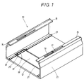
- in schaubildlicher Darstellung einen Kabelkanal mit einer ersten Ausführungsform der zugehörigen Halteklammer, wobei diese noch mit dem Kabelkanalunterteil verbunden ist und bei fehlendem Deckel,
- Fig. 2
- ebenfalls in schaubildlicher Darstellung und bei fehlendem Deckel eine abweichende Ausführungsform des Kabelkanals mit einer zweiten erfindungsgemäß ausgebildeten Halteklammer, letztere noch mit dem Kabelkanalunterteil verbunden,
- Fig. 3
- in Draufsicht und teilweise weggebrochen sowie in verkleinertem Maßstab denjenigen Bereich eines Kabelkanalunterteils, in dem sich die ausgestanzte Halteklammer befindet,
- Fig. 4
- im vergrößerten Maßstab und in schaubildlicher Darstellung einen weiteren Kabelkanal, bei fehlendem Deckel, mit einer dritten Ausführungsform der erfindungsgemäß vorgestanzten Halteklammer, wobei diese noch mit dem Boden des Kabelkanalunterteils verbunden ist,
- Fig. 5
- im verkleinerten Maßstab und im Querschnitt einen weiteren Kabelkanal mit einer vierten Ausführungsform der erfindungsgemäßen Halteklammer, wobei diese jedoch bereits in ihre wirksame Lage überführt ist, und bei in strichpunktierten Linien wiedergegebener Lage des Deckels des Kabelkanalunterteils,
- Fig. 6
- eine Draufsicht auf den Kabelkanal nach der Fig. 5, bei entferntem Deckel und bei derjenigen Lage der ausgestanzten Halteklammer, den diese vor dem Entfernen aus dem Boden des Kabelkanalunterteils einnimmt,
- Fig. 7
- einen Längsschnitt durch eine fünfte Ausführungsform der vorgestanzten Halteklammer,
- Fig. 8
- eine Draufsicht auf einen im verkleinerten Maßstab wiedergegebenen Haltekanal, wobei in dieser Figur die Lage der Halteklammer nach Fig. 7 wiedergegeben ist, den diese nach dem Vorstanzen im Boden des Kabelkanalunterteils einnimmt, und
- Fig. 9
- im vergrößerten Maßstab und in schaubildlicher Darstellung einen weiteren Kabelkanal bei fehlendem Deckel, bei dem im Boden vorgestanzte Trennwandabschnitte vorgesehen sind, wobei diese noch mit dem Boden des Kabelkanalunterteils verbunden sind.
- Fig. 1
- a diagram of a cable duct with a first embodiment of the associated retaining clip, which is still connected to the lower part of the cable duct and if the cover is missing,
- Fig. 2
- likewise in a diagrammatic representation and in the absence of a cover, a different embodiment of the cable duct with a second retaining clip designed according to the invention, the latter still connected to the lower part of the cable duct,
- Fig. 3
- in plan view and partially broken away and on a smaller scale that area of a cable duct lower part in which the punched-out retaining clip is located,
- Fig. 4
- on an enlarged scale and in a diagrammatic representation, a further cable duct, in the absence of a cover, with a third embodiment of the holding clip pre-punched according to the invention, which is still connected to the bottom of the cable duct lower part,
- Fig. 5
- on a reduced scale and in cross section, another cable duct with a fourth embodiment of the retaining clip according to the invention, but this is already transferred into its effective position, and in dash-dotted lines reproduced position of the cover of the lower part of the cable duct,
- Fig. 6
- 5, with the cover removed and in the position of the punched-out retaining clip which it occupies before being removed from the bottom of the lower part of the cable duct,
- Fig. 7
- 2 shows a longitudinal section through a fifth embodiment of the pre-punched holding clip,
- Fig. 8
- a plan view of a holding channel reproduced on a reduced scale, wherein in this figure the position of the holding clip is shown in FIG. 7, which it takes after the pre-punching in the bottom of the cable duct lower part, and
- Fig. 9
- on an enlarged scale and in a diagrammatic representation, a further cable duct in the absence of a cover, in which pre-punched partition sections are provided in the bottom, these being still connected to the bottom of the lower part of the cable duct.
Es sei zunächst erwähnt, daß in den Figuren der Zeichnungen nur diejenigen Teile eines Kabelkanals wiedergegeben sind, die für das Verständnis der Erfindung Bedeutung haben. So ist insbesondere weitgehend auf die Darstellung eines Deckels verzichtet, der die obere Öffnung des Kabelkanalunterteils verschließt, und der mit bekannten Mitteln, insbesondere mit Rastverbindungen mit dem Kabelkanalunterteil verbunden werden kann. Auch sind die in dem Aufnahmeraum des Kabelkanalunterteils unterzubringenden elektrischen Geräte, Einrichtungen u.dgl. nicht mit dargestellt. Diese können eine an sich bekannte Ausbildung haben und in ebenfalls bekannter Weise in dem Aufnahmeraum eines Kabelkanalunterteils untergebracht werden.It should first be mentioned that only those parts of a cable duct which are important for understanding the invention are shown in the figures of the drawings. In particular, there is largely no representation of a cover which closes the upper opening of the lower part of the cable duct and which can be connected to the lower part of the cable duct using known means, in particular with snap-in connections. Also, the electrical devices, devices and the like to be accommodated in the receiving space of the lower part of the cable duct. not shown. These can have a design which is known per se and can also be accommodated in the receiving space of a lower part of a cable duct in a known manner.
Der dem Ausführungsbeispiel nach der Fig. 1 der Zeichnung zugrundeliegende Kabelkanal ist generell mit 10 bezeichnet. In dieser Fig. 1 ist nur der nicht näher bezeichnete Kabelkanalunterteil wiedergegeben, dessen obere Öffnung durch einen grundsätzlich bekannten Deckel verschlossen werden kann. Bei dem Kabelkanal 10 gemäß der Fig. 1 handelt es sich um einen einstückigen Hohlkörper von im wesentlichen U-förmiger Querschnittsgestalt. Die Seitenwandungen des Kabelkanals 10 sind dabei mit 11 bezeichnet. In ihrem unteren Bereich werden die Seitenwandungen durch einen Boden 12 miteinander verbunden; dieser liegt quer zu den Seitenwandungen 11. Auf der Innenseite des Bodens 12 sind in Kabelkanallangsrichtung durchlaufende Leisten 13 vorgesehen. Diese Leisten 13 haben einen pilzkopfartigen Kopfbereich, d.h. der nicht näher bezeichnete Verbindungsteil der Leiste 13 geht über eine Schulter in den Pilzkopf über.The cable duct on which the exemplary embodiment according to FIG. 1 of the drawing is based is generally designated by 10. In this FIG. 1 only the lower part of the cable duct is shown, the upper opening of which can be closed by a basically known cover. The
Der obere Teil der Seitenwände 11 ist nach innen gezogen. Im Endbereich dieser Einziehung befindet sich jeweils eine durchlaufende Rast 14. Mit dieser Rast 14 können Gegenrasten des nicht dargestellten Deckels zusammenwirken, uni diesen mit dem Kabelkanalunterteil lösbar zu verbinden.The upper part of the
An der Innenseite der Seitenwandungen 11, und zwar am äußeren Ende, ist jeweils ein Innenflansch 15 vorgesehen. Die Stirnflächen der beiden Innenflansche 15 der diametral gegenüberliegenden Seitenwände 11 zeigen aufeinander zu. Jeder der beiden Innenflansche 15 hat zunächst einen breitenmäßig größeren, langgestreckten Durchbruch 16, der unter Bildung einer Schulter in einen schmaleren Durchbruch 17 übergeht. Der Durchbruch 17 ist etwa gleich lang wie der Durchbruch 16, jedoch ist der Durchbruch 17 breitenmäßig wesentlich kleiner bemessen. In der Fig. 1 ist jeweils bei einem Innenflansch 15 nur ein Durchbruch 16 bzw. ein weiteren Durchbruch 17 vorgesehen. Insbesondere bei langer bemessenen Kabelkanälen 10 kann die Anzahl der Durchbrüche 16 bzw. 17, die dem Innenflansch 15 zugeordnet sind, wesentlich vergrößert werden.An
Erfindungsgemäß ist nun im Boden 12 des Kabelkanals 10 mindestens eine Halteklammer vorgestanzt; diese ist im gewählten Ausführungsbeispiel mit 18 bezeichnet. Das Vorstanzen der Halteklammer 18 geschieht soweit, daß diese Halteklammer nur über zwei Haltestege mit dem Boden 12 des Kabelkanals 10 verbunden bleibt. Diese, in der Fig. 1 nicht dargestellten Haltestege können zerstört werden, beispielsweise lassen sie sich mit einem Werkzeug durchtrennen. Die Halteklammern 18 lassen sich aber auch durch Druckeinwirkung von, Boden 12 trennen, wobei ein Zerstören der Haltestege durch diesen Druck erfolgt.According to the invention, at least one retaining clip is now pre-punched in the bottom 12 of the
Wie die Fig. 1 der Zeichnungen erkennen läßt, verläuft die Halteklammer 18 quer zu den Seitenwandungen 11. Die Halteklammer 18 erfaßt auch die Leisten 13. Es wird von diesen Leisten 13 ein kleiner Abschnitt 19 abgetrennt. Dieser Abschnitt 19 ist der Befestigungsteil der Halteklammer 18. Nach dem Entfernen der Halteklammer 18 aus dem Boden 12 wird diese um 180° gedreht. Danach werden die Befestigungsteile 19, dies sind die abgetrennten Abschnitte der Leiste 13, durch den Durchbruch 16 des Innenflansches 15 hindurchgeführt. Nach dem Durchführen kann eine Verschiebung der Halteklammer in Kabellängsrichtung erfolgen. Dies hat den Erfolg, daß die Stege des Leistenabschnittes 19 zwar in den Durchbruch 17 des Innenflansches 15 gelangen können, die Schultern des Pilzkopfes legen sich jedoch gegen die Begrenzungswandungen des Durchbruches 17, so daß ein Herausziehen der Halteklammer 18 aus dem Durchbruch 17 nicht mehr möglich ist. Auf diese Weise ist mit einfachen Mitteln eine Lagesicherung der Halteklammer 18 an den Seitenwandungen 11 des Kabelkanals herbeigeführt.As can be seen in FIG. 1 of the drawings, the retaining
Wie aus der Fig. 1 der Zeichnung ersichtlich, sind die Leisten 13 so an der Innenfläche des Bodens 12 des Kabelkanals 10 angeformt, daß sie unterhalb der Unterseite des Innenflansches 15 liegen. Der Einfachheit halber ist in der Fig. 1 nur das Ausstanzen einer einzigen Halteklammer 18 wiedergegeben. Selbstverständlich könnte insbesondere bei längeren als den dargestellten Kabelkanälen auch eine größere Anzahl von Halteklammern im Bereich des Bodens 12 des Kabelkanals 10 vorgestanzt werden.As can be seen from FIG. 1 of the drawing, the
Im dargestellten Ausführungsbeispiel nach der Fig. 1 der Zeichnung ist der mittlere Bereich der Halteklammer 18, also der Bereich der zwischen den Befestigungsleisten 19 liegt, eben gehalten. Sofern größere Druckkräfte durch die Halteklammer 18 aufgenommen werden müssen, kann man in diesem Bereich auch eine Profilierung, z.B. eine Warmprägung, vornehmen. Durch eine solche Profilierung kann die Stabilität der Halteklammer 18 wesentlich verbessert werden.In the illustrated embodiment according to FIG. 1 of the drawing, the middle region of the holding
In den Fig. 2 und 3 der Zeichnungen ist eine weitere Ausführungsform des Kabelkanals 10 gemäß der Erfindung wiedergegeben. Das Grundprofil des Kabelkanals 10 ist dabei beibehalten. Es liegt somit wiederum ein im wesentlichen U-förmigen Querschnitt aufweisender Kabelkanalunterteil vor, der eine obere Öffnung aufweist, die in bekannter Weise durch einen Deckel verschlossen werden kann. Abweichend von dem Ausführungsbeispiel des Kabelkanals nach der Fig. 1 der Zeichnung sind die in Längsrichtung durchlaufenden Leisten 13 nunmehr in der Mitte des Bodens 12 angeordnet. In der Mitte zwischen den beiden Leisten 13 liegend ist eine weitere Leiste vorgesehen, die jetzt mit 26 bezeichnet ist, und die eine im Querschnitt rechteckige Gestalt aufweist. Gemäß der Erfindung ist im Boden 12 des Kabelkanals 10 nach den Fig. 2 und 3 wiederum eine Halteklammer vorgestanzt, diese ist jedoch nunmehr mit 25 bezeichnet. Die Lage der Halteklammer 25 ist im Vergleich mit der Lage der Halteklammer 18 nach der Fig. 1 geändert worden, und zwar liegt die Halteklammer 25 nunmehr in Längsrichtung des Kabelkanals 10. Beim Vorstanzen der Halteklammer 25 werden daher nicht nur die Leisten 13, sondern auch die mittige Halteleiste 26 erfaßt. Es entsteht jeweils im Bereich der einen Stirnseite der Halteklammer 25 liegend ein Haltevorsprung 24. An diesen schließt sich jeweils ein Durchbruch 27 an, der, wie die Fig. 3 am besten erkennen läßt, etwa quadratisch gehalten ist. Die Halteklammer 25 bleibt nach ihrem Vorstanzen nur über Haltestege 28 mit dem Boden 12 verbunden. Diese Haltestege 28 liegen diagonal versetzt mit dem Boden 12 verbunden. Diese Haltestege 28 liegen diametral versetzt zueinander. Durch Entfernen der Haltestege 28 kann ein vollständiges Trennen der Halteklammer 25 vom Boden 12 des Kabelkanals 10 erfolgen.2 and 3 of the drawings show a further embodiment of the
Die Fig. 2 der Zeichnungen läßt erkennen, daß auch der Kabelkanal 10 nach dieser Ausführungsform mit insgesamt zwei Innenflanschen 15 versehen ist, jedoch ist dieser Innenflansch mit anderen Einrichtungen versehen, die ein Anbringen der jetzt mit 25 bezeichneten Halteklammer an diesem Innenflansch 15 ermöglichen. Es sind nämlich im Bereich des Halteflansches 15 Schlitze 22 vorgesehen, die zum freien Ende des Innenflansches 15 hin offen sind Zwischen zwei dieser Schlitze 22 liegt jeweils eine Ausnehmung 23, die allseitig von Material umgeben ist. Beim Anbringen der Halteklammer 25 an den Innenflanschen 15 des Kabelkanals 10 wirken diese Vorsprünge 24 der Halteklammer mit den Ausnehmungen 23 zusammen. Auf der anderen Seite wirken die Stege der abgetrennten Abschnitte der Leisten 13 mit den Schlitzen 22 zusammen. Die Schultern im Bereich der Pilzköpfe der Leisten 13 liegen an den Begrenzungswandungen der Schlitze 22 an.Fig. 2 of the drawings shows that the
Die in der Fig. 4 wiedergegebene Ausführungsform eines Kabelkanals 10 hat wiederum einen Kabelkanalunterteil von im wesentlichen U-förmigem Querschnitt, also mit parallel und im Abstand zueinander angeordneten Seitenwandungen 11, die durch einen Boden 12 verbunden sind. Jedoch sind die Innenflansche, die am oberen Ende der Seitenwandungen 11 liegen und mit 15 bezeichnet sind, nunmehr abweichend von dem bisherigen Ausführungsformen gestaltet, das gleiche gilt auch für die an der Innenseite des Bodens 12 liegenden Leisten.The embodiment of a
Wie die Fig. 4 erkennen läßt, sind in der Nähe der Seitenwandungen 11, an der Innenseite des Bodens 12 liegend, durchlaufende Leisten 29 vorgesehen, die im Querschnitt gesehen L-förmige Gestalt aufweisen. Der im Abstand vom Boden liegende Schenkel dieses L's zeigt dabei auf die Innenseite der Seitenwand 11.As can be seen in FIG. 4,
Im Abstand davon, und zwar näher an der Innenseite der Seitenwand 11 liegend, ist eine weitere Leiste 31 vorgesehen. Diese hat eine im Querschnitt gesehen dreieckförmige Gestalt, wobei die Spitze dieses Dreiecks dem freien Schenkel des L's der Leiste 29 zugekehrt ist. Zwischen dieser Spitze und der benachbarten Kante der Leiste 29 ist ein nicht näher bezeichneter Schlitz vorgesehen. Sowohl die Leiste 29 als auch die weitere Leiste 31 sind der Innenseite des Bodens 12 des Kabelkanals 10 unmittelbar angeformt.A
Erfindungsgemäß wird nunmehr im Boden 12 eine jetzt mit 32 bezeichnete Halteklammer vorgestanzt. Die Trennlinie zwischen dieser Halteklammer 32 und dem verbleibenden Boden 12 des Kabelkanals ist mit 34 bezeichnet. Die Halteklammer 32 ist lediglich über zwei in der Fig. 4 nicht sichtbare Haltestege mit dem Boden verbunden, wobei diese Haltestege zum Entfernen der Halteklammer 32 aus dem Boden zerstört werden. Die Halteklammer 32 erfaßt auch die Bereiche der beiden Leisten 29 und 31. Es entstehen beim Stanzen der Halteklammer 32 Halteteile 33, die in Abstand voneinander liegen und untereinander gleichgestaltet sind. Diese Halteteile 33 wirken nach dem Entfernen der Halteklammer 32 aus dem Boden 12 des Kabelkanals 10 mit Ausnehmungen 30 zusammen, die in größerer Anzahl jeweils im Bereich des Innenflansches 15 angeordnet sind. Die Ausnehmungen 30 sind in Draufsicht gesehen rechteckig gehalten, wobei die Abmessungen dieser Ausnehmungen denjenigen der Halteteile 33 der Halteklammer 32 angepaßt sind.According to the invention, a holding clip, now designated 32, is now pre-punched in the
Im dargestellten Ausführungsbeispiel ist der gesamte Mittelbereich der Halteklammer 32 eben gehalten. Für den Fall, daß größere Druckkräfte von der Halteklammer 32 aufgenommen werden müssen, kann dieser Bereich auch profiliert sein. Die Anzahl der anzubringenden Profile und deren Aussehen kann abgewandelt werden.In the illustrated embodiment, the entire central region of the holding
Bei den Ausführungsformen des Kabelkanals nach den Fig. 1 bis 4 der Zeichnung ist vorgesehen, daß die vorgestanzte Halteklammer jeweils die im Bereich des Bodens vorgesehenen Leisten erfaßt, unabhängig davon, welche Querschnittsgestalt diese Leisten haben.In the embodiments of the cable duct according to FIGS. 1 to 4 of the drawing, it is provided that the pre-punched retaining clip in each case Area of the floor provided strips, regardless of the cross-sectional shape of these strips.
In den Fig. 5 und 6 der Zeichnungen ist eine andere erfindungsgemäße Lösung vorgeschlagen. Diese unterscheidet sich von der bisher geschilderten dadurch, daß die vorgestanzte Halteklammer nicht mehr Bereiche der Leisten des Bodens 12 erfaßt.Another solution according to the invention is proposed in FIGS. 5 and 6 of the drawings. This differs from the one described so far in that the pre-punched retaining clip no longer covers areas of the strips of the
Bei dem Ausführungsbeispiel des Kabelkanals 10 nach den Fig. 5 und 6 der Zeichnungen ist wiederum ein im Querschnitt U-förmiger Kabelkanalunterteil vorgesehen. Auf diesen kann, wie in Fig. 5 in strichpunktierten Linien dargestellt, ein Deckel 35 aufgeschnappt werden. An der Innenseite des Bodens 12 sind dem Kabelkanalunterteil in Längsrichtung des Kabelkanals 10 durchlaufende Leisten 13 zugeordnet; diese haben wiederum pilzkopfförmigen Querschnitt. Es sind insgesamt vier derartiger Leisten 13 am Boden vorgesehen.In the exemplary embodiment of the
Gemäß dem Ausführungsbeispiel nach den Fig. 5 und 6 der Zeichnung ist nun im Bereich zwischen den beiden mittleren Leisten 13 eine jetzt mit 36 bezeichnete Halteklammer vorgestanzt. Das Vorstanzen der Halteklammer 36 erfolgt so, daß die Pilzköpfe der Leisten 13 nicht erfaßt werden. Die Trennlinie liegt also neben den durchlaufenden Leisten 13.According to the embodiment of FIGS. 5 and 6 of the drawing, a holding clip, now designated 36, is now pre-punched in the area between the two
Wie die Fig. 6 am besten erkennen läßt, hat die Halteklammer 36 einen ebenen, nicht näher bezeichneten Mittelbereich. In der Mitte desselben sind zwei Haltestege 42 vorgesehen, die diametral gegenüberliegend angeordnet sind, und die die Verbindung der Halteklammer 36 mit dem Boden 12 des Kabelkanals 10 zunächst aufrechterhalten. Jeder Endbereich der Halteklammer 36 ist in zwei Arme aufgeteilt. Dies bedeutet, daß jedes Ende der Halteklammer 36 einen Halteklammerarm 37 sowie einen weiteren Halteklammerarm 38 aufweist. Diese beiden Haltearme 37 und 38 sind durch einen Zwischenraum 39 voneinander getrennt. Es handelt sich dabei uni einen schlitzförmigen Zwischenraum, der in Richtung auf das freie Ende hin offen ist. Im Bereich der Öffnung des Zwischenraumes 39 ist der Halteklammerarm 37 abgeschrägt, derart, daß er in eine Spitze ausläuft. In Nähe des Zwischenraumeintrittes 43 hat der Halteklammerarm 38 einen Vorsprung 40, der im gewählten Ausführungsbeispiel ein massiver Körper mit kreisförmigem Querschnitt ist.As can best be seen in FIG. 6, the holding
Nach dem Zerstören der Haltestege 42 wird die Halteklammer 36 aus dem Boden 12 des Kabelkanals 10 herausgenommen und in der in Fig. 5 dargestellten Art und Weise mit den Innenflanschen 15 der Seitenwände 11 verbunden. Daraus ergibt sich, daß die Vorsprünge 40 der Halteklammerarme 38 der Halteklammer 36 mit diametral gegenüberliegenden, kreisförmigen Durchbrüchen der Innenflansche 15 zusammenwirken. Die kreisförmigen Durchbrechungen 41 sind dabei in größerer Anzahl an den Innenflanschen 15 vorgesehen. Sie sind untereinander gleichgestaltet und liegen in regelmäßigen Abständen. Selbstverständlich wäre es ohne weiteres möglich, ein und demselben Kabelkanal 10 mehr als eine Halteklammer 36 zuzuordnen.After the retaining
In den Fig. 7 und 8 der Zeichnungen ist ein weiteres Ausführungsbeispiel eines erfindungsgemäßen Kabelkanals dargestellt. Bei dieser Ausführungsform hat der Kabelkanalboden 12 überhaupt keine Leiste, er ist völlig eben gehalten. Wie die Fig. 8 erkennen läßt, ist in der Mitte eines solchen Kabelkanals 10 eine jetzt mit 44 bezeichnete Halteklammer vorgestanzt. Die Halteklammer 44 ist in der in der Fig. 8 dargestellten Lage über die Haltestege 45 noch mit dem restlichen Boden 12 verbunden. Ansonsten ist eine Durchtrennung zum Boden hin erfolgt.7 and 8 of the drawings, a further embodiment of a cable duct according to the invention is shown. In this embodiment, the
Die beiden freien Enden der Halteklammer 44 haben jeweils zwei Außenarme 47. Diese sind über jeweils einen Zwischenraum 51 von einem Mittelarm 48 getrennt. Die beiden Seitenarme 47 sind jeweils untereinander gleichgestaltet, das gleiche gilt auch für die Ausbildung des Zwischenraumes 51. Der Mittelarm 48 hat an seiner einen Außenseite liegend, und zwar im Bereich seines vorderen Endes, einen Haltevorsprung 49, der im Querschnitt kreisförmig gestaltet ist.The two free ends of the holding
Über die Länge der Halteklammer 44 verteilt sind die Biegekanten 50 vorgesehen. Durch die Verwendung solcher Biegekanten können Bereiche der Halteklammer 44 aus der Grundebene herausgebogen werden, so wie dies in der Fig. 7 der Zeichnungen wiedergegeben ist. Daraus folgt, daß die beiden freien Enden der Halteklammer 44 aus der horizontalen Grundfläche herausgebogen sind. Nach dem Entfernen der Halteklammer 44 aus dem Boden 12 des Kabelkanals nach der Fig. 8 der Zeichnungen kann diese Halteklammer z.B. in eine der kreisförmigen Ausnehmungen der Innenflansche 15 eingeführt werden.The bending edges 50 are provided over the length of the holding
In der Fig. 9 der Zeichnungen ist ein weiteres Ausführungsbeispiel eines erfindungsgemäßen Kabelkanals wiedergegeben. Auch dieser Kabelkanal hat wiederum einen im wesentlichen U-förmigen Querschnitt aufweisenden Kabelkanalunterteil mit Seitenwandungen 11, die über einen Boden 12 miteinander verbunden sind. Dabei sind wiederum an den oberen Enden der Seitenwandungen nach außen ragende Rasten vorgesehen, die dem Anbringen eines Deckels dienen.9 of the drawings shows a further exemplary embodiment of a cable duct according to the invention. This cable duct in turn also has an essentially U-shaped cross-section of the lower part of the cable duct with
Bei der Ausführungsform des Kabelkanals nach der Fig. 9 der Zeichnung ist jedoch im Bereich des Bodens keine Halteklammer vorgestanzt, sondern ein mit 52 bezeichneter Trennwandabschnitt. Diese, einen Bestandteil des Bodens bildende Trennwand besteht aus zwei Trennwandzungen 53 und 54, wobei die eine, nämlich die mit 54 bezeichnete, ein Bestandteil des Bodens 12 ist, während die mit 53 bezeichnete spitzwinklig dazu angeordnet ist. Die beiden Trennwandzungen 53 und 54 laufen in einen nicht näher bezeichneten Scheitel aus. Zwischen den beiden Trennwandzungen 53 und 54 liegt ein Zwischenraum 56, der im Querschnitt gesehen etwa dreieckförmige Gestalt aufweist. Im Bereich des vorderen Endes der Trennwandzunge 54 ist an der Innenseite des Bodens 12 liegend, eine leistenförmige Verdickung 55 vorgesehen. Diese läuft in Längsrichtung des Kabelkanals 10 durch und hat eine dreieckförmige Querschnittsgestalt, wobei die Spitze des Dreiecks in Richtung auf die Trennwandzunge 53 zeigt. Zwischen dieser Spitze der leistenförmigen Verdickung 55 und dem vorderen Ende der Trennwandzunge 53 ist ein Spalt vorhanden.In the embodiment of the cable duct according to FIG. 9 of the drawing, however, no retaining clip is pre-punched in the area of the bottom, but rather a partition section designated 52. This partition, which forms part of the base, consists of two
Die Fig. 9 zeigt auch, daß an der Innenseite des Bodens 12 eine durchlaufende Leiste 13 angeordnet ist. Diese besteht wiederum aus einem Steg und einem Pilzkopf. Es ist aus der Fig. 9 ferner zu erkennen, daß der ausgestanzte Trennwandabschnitt 52 von den übrigen Bereichen frei ist und damit aus dem Boden entfernt werden kann. Nach dem Entfernen kann der Trennwandabschnitt 52 auf einen durchlaufenden Bereich der Leiste 13 aufgeschnappt werden, was in bekannter Weise erfolgen kann. Nach dem Aufschnappen des Trennwandabschnittes 52 befindet sich der Pilzkopf der Leiste 13 im Zwischenraum 56 zwischen den Trennwandzungen 53 und 54.Fig. 9 also shows that a
Wie bereits erwähnt, sind die dargestellten Ausführungen nur beispielsweise Verwirklichungen der Erfindung und diese nicht darauf beschränkt. Vielmehr sind noch mancherlei andere Ausführungen und Anwendungen möglich. Insbesondere kann die Gestalt und die Ausbildung der auszustanzenden bzw. vorzustanzenden Halteklammern abweichend von den dargestellten Ausführungen gewählt werden. Auch können ein und demselben Boden mehrere vorzustanzende Halteklammern zugeordnet werden, nur muß dabei darauf geachtet werden, daß die Stabilität des Kabelkanalunterteils dadurch nicht leidet. Die vorgestanzten oder ausgestanzten Halteklammern können einen eben gehaltenen Mittelteil aufweisen. Darüber hinaus ist es aber auch möglich, diese mit Prägungen zu versehen, z.B. dann, wenn die Halteklammern durch Druckkräfte belastet werden. Neben den Halteklammern und der Trennwand können ggf. auch andere Teile aus dem Boden oder einer Seitenwand eines Kabelkanals ausgestanzt werden.As already mentioned, the illustrated embodiments are only examples of implementations of the invention and are not limited to them. Rather, there are many other designs and applications possible. In particular, the shape and design of the retaining clips to be punched out or pre-punched can be selected differently from the embodiments shown. It is also possible to assign several retaining clips to be pre-punched to one and the same floor, only care must be taken that the stability of the lower part of the cable duct does not suffer as a result. The pre-punched or punched out retaining clips can have a flat middle section. In addition, however, it is also possible to provide these with embossments, for example when the holding clips are loaded by compressive forces. In addition to the retaining clips and the partition, other parts can also be punched out of the floor or a side wall of a cable duct.
- 1010th
- KabelkanalCabel Canal
- 1111
- Seitenwand (von 10)Sidewall (of 10)
- 1212th
- Boden (von 10)Floor (out of 10)
- 1313
- Leisten (an 12)Last (at 12)
- 1414
- Rasten (an 11)Notches (at 11)
- 1515
- Innenflansch (von 11)Inner flange (from 11)
- 1616
- großer Durchbruch (in 15)big breakthrough (in 15)
- 1717th
- kleiner Durchbruch (in 15)small breakthrough (in 15)
- 1818th
- Halteklammer (I. Ausf.) Fig. 1Retaining clip (1st version) Fig. 1
- 1919th
- Befestigungsleiste (von 18)Mounting ledge (of 18)
- 2020th
- Pilzkopf (von 19)Mushroom head (from 19)
- 2121
- Trennlinie (von 18 in 12)Dividing line (from 18 to 12)
- 2222
- Schlitz (in 15)Slot (in 15)
- 2323
- Ausnehmung (in 15)Recess (in 15)
- 2424th
- Vorsprung (an 25)Tab (at 25)
- 2525th
- Halteklammer (II. Ausf.) Fig. 2 u. 3Retaining clip (II. Ausf.) Fig. 2 u. 3rd
- 2626
- Leiste (an 12)Bar (on 12)
- 2727
- Durchbruch (von 25)Breakthrough (of 25)
- 2828
- Haltesteg (für 25 an 12)Footbridge (for 25 to 12)
- 2929
- L-förmige Leiste (an 12; Fig. 4)L-shaped bar (on 12; Fig. 4)
- 3030th
- Ausnehmung (in 15)Recess (in 15)
- 3131
- Halteprofil (an 12; Fig. 4)Holding profile (at 12; Fig. 4)
- 3232
- Halteklammer (III. Ausf. Fig. 4)Retaining clip (III. Ausf. Fig. 4)
- 3333
- Halteteile (von 32)Holding parts (of 32)
- 3434
- Trennlinie (zwischen 12 u. 32, Fig. 4)Dividing line (between 12 and 32, Fig. 4)
- 3535
- Deckelcover
- 3636
- Halteklammer (IV. Ausf. Fig. 5 u. 6)Retaining clip (IV. FIGS. 5 and 6)
- 3737
- Halteklammerarm (von 36)Bracket arm (of 36)
- 3838
- Halteklammerarm (von 36)Bracket arm (of 36)
- 3939
- Zwischenarm (zwischen 37 u. 38)Forearm (between 37 and 38)
- 4040
- Haltevorsprung (an 38)Retaining tab (on 38)
- 4141
- kreisförmiger Durchbruch (in 15)circular breakthrough (in 15)
- 4242
- Haltesteg (für 36)Footbridge (for 36)
- 4343
- ZwischenraumeintrittGap entry
- 4444
- Halteklammer (V. Ausf. Fig. 7 + 8)Holding clip (V. Ausf. Fig. 7 + 8)
- 4545
- Haltesteg (für 44)Holding bridge (for 44)
- 4646
- Freiraum (in 12 für 44)Free space (in 12 for 44)
- 4747
- Außenarme (von 44)Outer Arms (of 44)
- 4848
- Mittelarm (von 44)Middle arm (of 44)
- 4949
- Haltevorsprung (an 48)Retaining tab (on 48)
- 5050
- Biegekanten (von 44)Bending edges (of 44)
- 5151
- Zwischenraum (zwischen 47 u. 48)Space (between 47 and 48)
- 5252
- ausgestanzter Trennwandabschnittpunched-out partition section
- 5353
- TrennwandzungePartition tongue
- 5454
- TrennwandzungePartition tongue
- 5555
- leistenförmige Verdickung (von 54)strip-shaped thickening (of 54)
- 5656
- Zwischenraum (zwischen 53 u. 54)Space (between 53 and 54)
Claims (25)
dadurch gekennzeichnet,
daß Teile des Kabelkanals (10), vorzugsweise des Kabelkanalunterteils selbst, als Halteklammer (18, 25, 32, 36, 44) und/oder als Trennwand (52) benutzbar sind.Cable duct, consisting of a lower part of a cable duct and a cover that can be detachably connected to it, in which the side walls of the lower part of the cable duct are connected to each other by holding clips and the bottom of the lower part of the cable duct has holding strips that extend in the longitudinal direction and, if necessary, for detachably attaching at least one to the receiving space of the lower part of the cable duct Partitions dividing chambers can be used,
characterized,
that parts of the cable duct (10), preferably the lower part of the cable duct itself, can be used as a retaining clip (18, 25, 32, 36, 44) and / or as a partition (52).
Priority Applications (3)
| Application Number | Priority Date | Filing Date | Title |
|---|---|---|---|
| EP95106954A EP0742625B1 (en) | 1995-05-09 | 1995-05-09 | Trunking |
| DE59503338T DE59503338D1 (en) | 1995-05-09 | 1995-05-09 | Cabel Canal |
| AT95106954T ATE170342T1 (en) | 1995-05-09 | 1995-05-09 | CABEL CANAL |
Applications Claiming Priority (1)
| Application Number | Priority Date | Filing Date | Title |
|---|---|---|---|
| EP95106954A EP0742625B1 (en) | 1995-05-09 | 1995-05-09 | Trunking |
Publications (2)
| Publication Number | Publication Date |
|---|---|
| EP0742625A1 true EP0742625A1 (en) | 1996-11-13 |
| EP0742625B1 EP0742625B1 (en) | 1998-08-26 |
Family
ID=8219233
Family Applications (1)
| Application Number | Title | Priority Date | Filing Date |
|---|---|---|---|
| EP95106954A Expired - Lifetime EP0742625B1 (en) | 1995-05-09 | 1995-05-09 | Trunking |
Country Status (3)
| Country | Link |
|---|---|
| EP (1) | EP0742625B1 (en) |
| AT (1) | ATE170342T1 (en) |
| DE (1) | DE59503338D1 (en) |
Cited By (8)
| Publication number | Priority date | Publication date | Assignee | Title |
|---|---|---|---|---|
| FR2777130A1 (en) * | 1998-04-03 | 1999-10-08 | Planet Wattohm Sa | CHUTE SUITABLE TO BE CUT ON DEMAND |
| FR2839134A1 (en) | 2002-04-30 | 2003-10-31 | Planet Wattohm Sa | Trough for carrying electric cables, comprises trough base with integral retaining clip supported on weak hinge which on removal combines with fixed hinge and clasp on trough base to secure cables |
| EP1359652A1 (en) * | 2002-04-30 | 2003-11-05 | Tehalit GmbH & Co. KG | Cable channel |
| EP2028738A1 (en) | 2007-08-21 | 2009-02-25 | Tehalit GmbH | Bridging clamp for securing cables and leads in cable guide channels |
| EP2017933A3 (en) * | 2007-07-20 | 2010-11-03 | Tehalit GmbH | Bridging clamp for securing cables and leads in cable guide channels |
| EP2110913A3 (en) * | 2008-04-19 | 2011-07-13 | Tehalit GmbH | Cabling canal with anti-slip function |
| DE202012003820U1 (en) | 2012-04-17 | 2013-07-19 | Tehalit Gmbh | Wiring channel with safety function to prevent the lid from slipping |
| EP4123856A4 (en) * | 2020-03-18 | 2024-04-17 | Diaferia Flavio Albertini | Improvement of sets of modular raceways for structured optical-fiber cabling |
Citations (3)
| Publication number | Priority date | Publication date | Assignee | Title |
|---|---|---|---|---|
| DE1241511B (en) * | 1962-04-11 | 1967-06-01 | Kenneth Reiner | Cable duct for laying electrical cables on wall surfaces |
| EP0392956A2 (en) * | 1989-04-14 | 1990-10-17 | Aparellaje Electrico, S.A. | Device for stiffening of cable channels or ducts for electrical conductors or similar and corresponding clamps |
| EP0644640A2 (en) * | 1993-09-09 | 1995-03-22 | REHAU AG + Co | Installation raceway |
-
1995
- 1995-05-09 EP EP95106954A patent/EP0742625B1/en not_active Expired - Lifetime
- 1995-05-09 DE DE59503338T patent/DE59503338D1/en not_active Expired - Lifetime
- 1995-05-09 AT AT95106954T patent/ATE170342T1/en not_active IP Right Cessation
Patent Citations (3)
| Publication number | Priority date | Publication date | Assignee | Title |
|---|---|---|---|---|
| DE1241511B (en) * | 1962-04-11 | 1967-06-01 | Kenneth Reiner | Cable duct for laying electrical cables on wall surfaces |
| EP0392956A2 (en) * | 1989-04-14 | 1990-10-17 | Aparellaje Electrico, S.A. | Device for stiffening of cable channels or ducts for electrical conductors or similar and corresponding clamps |
| EP0644640A2 (en) * | 1993-09-09 | 1995-03-22 | REHAU AG + Co | Installation raceway |
Cited By (11)
| Publication number | Priority date | Publication date | Assignee | Title |
|---|---|---|---|---|
| FR2777130A1 (en) * | 1998-04-03 | 1999-10-08 | Planet Wattohm Sa | CHUTE SUITABLE TO BE CUT ON DEMAND |
| WO1999052190A1 (en) * | 1998-04-03 | 1999-10-14 | Planet Wattohm | Duct capable of being cut up as required |
| FR2839134A1 (en) | 2002-04-30 | 2003-10-31 | Planet Wattohm Sa | Trough for carrying electric cables, comprises trough base with integral retaining clip supported on weak hinge which on removal combines with fixed hinge and clasp on trough base to secure cables |
| EP1359653A1 (en) | 2002-04-30 | 2003-11-05 | Planet-Wattohm | Cable duct with integrated staples for retaining cables and cable duct including one or more components of this type |
| EP1359652A1 (en) * | 2002-04-30 | 2003-11-05 | Tehalit GmbH & Co. KG | Cable channel |
| EP2017933A3 (en) * | 2007-07-20 | 2010-11-03 | Tehalit GmbH | Bridging clamp for securing cables and leads in cable guide channels |
| EP2028738A1 (en) | 2007-08-21 | 2009-02-25 | Tehalit GmbH | Bridging clamp for securing cables and leads in cable guide channels |
| EP2110913A3 (en) * | 2008-04-19 | 2011-07-13 | Tehalit GmbH | Cabling canal with anti-slip function |
| DE202012003820U1 (en) | 2012-04-17 | 2013-07-19 | Tehalit Gmbh | Wiring channel with safety function to prevent the lid from slipping |
| EP2654151A2 (en) | 2012-04-17 | 2013-10-23 | Tehalit GmbH | Cabling canal with safety function to prevent the cover slipping off |
| EP4123856A4 (en) * | 2020-03-18 | 2024-04-17 | Diaferia Flavio Albertini | Improvement of sets of modular raceways for structured optical-fiber cabling |
Also Published As
| Publication number | Publication date |
|---|---|
| EP0742625B1 (en) | 1998-08-26 |
| ATE170342T1 (en) | 1998-09-15 |
| DE59503338D1 (en) | 1998-10-01 |
Similar Documents
| Publication | Publication Date | Title |
|---|---|---|
| DE19637835B4 (en) | Snap-in catch for flush mounted panels | |
| DE4309088C2 (en) | Fixed disc for motor vehicles | |
| EP0390062B1 (en) | Clamp shaped sheet metal nut for automatic assembly | |
| DE2512131A1 (en) | STORAGE STRIP FOR BOLT-SHAPED FASTENING ELEMENTS | |
| DE19649134B4 (en) | Cabel Canal | |
| EP0708001A1 (en) | Trim or cover moulding fastening device | |
| EP2630310B1 (en) | Frame profile system | |
| DE8302760U1 (en) | CLAMP FOR ATTACHING A PANEL CONSTRUCTION TO A WALL OR CEILING. | |
| DE3733329C1 (en) | Cable guide channel for receiving high voltage, low voltage and telecommunication cables | |
| EP2334887B1 (en) | Insertion connector | |
| EP0742625B1 (en) | Trunking | |
| DE69937025T2 (en) | CABLE CHANNEL AND ACCESSORIES THEREOF | |
| DE2353471A1 (en) | CABLE TRAY WITH CONNECTOR | |
| EP2273638A2 (en) | Clip for cable channels for laminating cut edges | |
| EP0539746B1 (en) | Protective device for frames | |
| DE19521862C2 (en) | Fastening device for a decorative or cover strip | |
| DE2644040C2 (en) | Angle connection for components, in particular profile strips, profile supports and the like. | |
| EP0932010B1 (en) | Heat exchanger | |
| EP1458455B1 (en) | Holding profile for lamellae, modular holding profile unit, and a separating, light-reducing or flow-conducting unit containing the same | |
| DE3200282C2 (en) | ||
| DE3302530A1 (en) | Blind covering strips for distributors | |
| DE3001942A1 (en) | Decorative or protective strip for car body - has C=section channel with cut or indented internal spring projections to locate fasteners | |
| EP2754832B1 (en) | Method and device for inserting a panel in a frame | |
| DE69811772T2 (en) | Band for a fastening clamp and fastening clamp | |
| EP1459938A1 (en) | Fastener for releasably attaching a member to a carrier |
Legal Events
| Date | Code | Title | Description |
|---|---|---|---|
| PUAI | Public reference made under article 153(3) epc to a published international application that has entered the european phase |
Free format text: ORIGINAL CODE: 0009012 |
|
| 17P | Request for examination filed |
Effective date: 19960626 |
|
| 17Q | First examination report despatched |
Effective date: 19970604 |
|
| GRAG | Despatch of communication of intention to grant |
Free format text: ORIGINAL CODE: EPIDOS AGRA |
|
| GRAG | Despatch of communication of intention to grant |
Free format text: ORIGINAL CODE: EPIDOS AGRA |
|
| GRAG | Despatch of communication of intention to grant |
Free format text: ORIGINAL CODE: EPIDOS AGRA |
|
| GRAH | Despatch of communication of intention to grant a patent |
Free format text: ORIGINAL CODE: EPIDOS IGRA |
|
| GRAH | Despatch of communication of intention to grant a patent |
Free format text: ORIGINAL CODE: EPIDOS IGRA |
|
| GRAA | (expected) grant |
Free format text: ORIGINAL CODE: 0009210 |
|
| ITF | It: translation for a ep patent filed |
Owner name: CALVANI SALVI E VERONELLI S.R.L. |
|
| AK | Designated contracting states |
Kind code of ref document: B1 Designated state(s): AT BE DE IT LU NL |
|
| PG25 | Lapsed in a contracting state [announced via postgrant information from national office to epo] |
Ref country code: NL Free format text: LAPSE BECAUSE OF FAILURE TO SUBMIT A TRANSLATION OF THE DESCRIPTION OR TO PAY THE FEE WITHIN THE PRESCRIBED TIME-LIMIT Effective date: 19980826 |
|
| REF | Corresponds to: |
Ref document number: 170342 Country of ref document: AT Date of ref document: 19980915 Kind code of ref document: T |
|
| REF | Corresponds to: |
Ref document number: 59503338 Country of ref document: DE Date of ref document: 19981001 |
|
| NLV1 | Nl: lapsed or annulled due to failure to fulfill the requirements of art. 29p and 29m of the patents act | ||
| PG25 | Lapsed in a contracting state [announced via postgrant information from national office to epo] |
Ref country code: LU Free format text: LAPSE BECAUSE OF NON-PAYMENT OF DUE FEES Effective date: 19990509 |
|
| PGFP | Annual fee paid to national office [announced via postgrant information from national office to epo] |
Ref country code: AT Payment date: 19990526 Year of fee payment: 5 |
|
| PGFP | Annual fee paid to national office [announced via postgrant information from national office to epo] |
Ref country code: DE Payment date: 19990529 Year of fee payment: 5 |
|
| PG25 | Lapsed in a contracting state [announced via postgrant information from national office to epo] |
Ref country code: BE Free format text: LAPSE BECAUSE OF NON-PAYMENT OF DUE FEES Effective date: 19990531 |
|
| PLBE | No opposition filed within time limit |
Free format text: ORIGINAL CODE: 0009261 |
|
| STAA | Information on the status of an ep patent application or granted ep patent |
Free format text: STATUS: NO OPPOSITION FILED WITHIN TIME LIMIT |
|
| 26N | No opposition filed | ||
| BERE | Be: lapsed |
Owner name: HERMANN KLEINHUIS G.M.B.H. & CO. K.G. Effective date: 19990531 |
|
| PG25 | Lapsed in a contracting state [announced via postgrant information from national office to epo] |
Ref country code: AT Free format text: LAPSE BECAUSE OF NON-PAYMENT OF DUE FEES Effective date: 20000509 |
|
| PG25 | Lapsed in a contracting state [announced via postgrant information from national office to epo] |
Ref country code: DE Free format text: LAPSE BECAUSE OF THE APPLICANT RENOUNCES Effective date: 20000623 |
|
| PG25 | Lapsed in a contracting state [announced via postgrant information from national office to epo] |
Ref country code: IT Free format text: LAPSE BECAUSE OF NON-PAYMENT OF DUE FEES;WARNING: LAPSES OF ITALIAN PATENTS WITH EFFECTIVE DATE BEFORE 2007 MAY HAVE OCCURRED AT ANY TIME BEFORE 2007. THE CORRECT EFFECTIVE DATE MAY BE DIFFERENT FROM THE ONE RECORDED. Effective date: 20050509 |